1
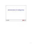
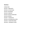
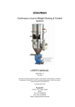
Load Cell Tester Type LCT-01
USER MANUAL
User Manual LCT-01
Page 1
Table of Content
The Strain Gauge Load Cell . . . . . . . . . . . . . . . . . . . . . . . . . . . 3
Functions of the LCT-O1 . . .
LCT-O1 Tests Performed . . .
Approximated Linearity Test .
Weighing Platform Balancing .
.
.
.
.
.
.
.
.
. . . .
. . . . .
. . . . .
. . . . .
.
.
.
.
.
.
.
.
.
.
.
.
.
.
.
.
.
.
.
.
. . . .
. . . . .
. . . . .
. . . . .
.
.
.
.
.
.
.
.
.
.
.
.
.
.
.
.
.
.
.
.
. . . .
. . . . .
. . . . .
. . . . .
.
.
.
.
.
.
.
.
4
4
4
4
LCT-01 Parts Identification. . . . . . . . . . . . . . . . . . . . . . . . . . . . 5
LCT-O1 Test Procedure . . . . . . . . .
Connecting the Load Cell conductors . . .
Load Cell Type . . . . . . . . . . . . . . .
Load Cell Output Rate . . . . . . . . . . .
Start Test . . . . . . . . . . . . . . . . . .
Dynamic Test . . . . . . . . . . . . . . . .
.
.
.
.
.
.
.
.
.
.
.
.
.
.
.
.
.
.
.
.
.
.
.
.
.
.
.
.
.
.
. . . .
. . . . .
. . . . .
. . . . .
. . . . .
. . . . .
.
.
.
.
.
.
.
.
.
.
.
.
.
.
.
.
.
.
.
.
.
.
.
.
.
.
.
.
.
.
. . . .
. . . . .
. . . . .
. . . . .
. . . . .
. . . . .
.
.
.
.
.
.
.
.
.
.
.
.
6
6
6
6
7
7
LCT-O1 Test Results . . . . . . . . . . . . . . . . . . . . . . . . . . . . . . . 8
Input / Output Test . . . . . . . . . . . . . . . . . . . . . . . . . . . . . . . . . . . 8
Shield / Ground Test . . . . . . . . . . . . . . . . . . . . . . . . . . . . . . . . . . 9
Sense position / Sense Neg. Test (6-conductor load cells only) . . . . . . . . . . . 10
Signal Output Test . . . . . . . . . . . . . . . . . . . . . . . . . . . . . . . . . . . 10
Load Cell Color Wiring Guide. . . . . . . . . . . . . . . . . . . . . . . . . . 11
Battery Installation . . . . . . . . . . . . . . . . . . . . . . . . . . . . . . . 12
Page 2
Manual LCT-01
1.
The Strain Gauge Load Cell
Strain gauge weighing is based on the measurement of the deformation of metal as a result
of compression, tension, flexion, shearing or torsion. A weight placed on a strain gauge load
cell deforms its component metal spring element, and this deformation is measured by the
strain gauges. The strain gauges, usually four or a multiple of four, are cemented to the
spring element. These strain gages are connected into a Wheatstone bridge configuration
(see Figure) in order to convert the very small change in resistance into a usable electrical
signal. In addition, passive components such as precision resistors and temperature
sensitive elements are used to compensate and calibrate the bridge output signal.
+ Input
(+ Sense)
+ Output
(– Sense)
– Input
– Output
Shield
The relation between the applied load and the output signal is done by calibration: applying
known loads and measuring the resultant output voltage. The resulting curve in most load
cells is almost linear, and this calibration allows for the conversion of the output signal to its
source: the applied load.
Consider the example of a load cell with a rated output of 2 mV/V, and a maximal load of 10
kg. If the output signal with no load is 0, feeding the load cell with 10 V excitation voltage will
result in an output signal of 20 mV when the applied load is 10 kg. Since the output signal is
linearly proportional to the load applied, a 5 kg load would give an output signal of 10 mV.
In every load cell the rated output, the excitation voltage, and the nominal load are defined in
the manufacturer’s specification.
A load cell is normally provided with a shielded, 4 conductor cable. The shield is not
connected to the load cell body (floating).
Attention: For certain applications the load cell shield is connected to the load cell body.
Check the manufacturer’s specifications.
In some occasions a 6 conductor cable is used (+Sense and –Sense added), having some
advantages for single point load cell applications.
Manual LCT-01
Page 3
2.
Functions of the LCT-O1
The LCT-01 is a hand-held, easy-to-use device which requires no special training or
expertise to operate. The LCT-01 tests either four-conductor or six-conductor load cells,
covering the whole range of load cell output.
The LCT-01 supplies a quick initial evaluation for all types of strain gauge load cells. Due to
its portability and design, the LCT-01 is useful not only in laboratories, but also on-site in
hard-to-access locations. The load cell can be tested without being removed from the
installation.
2.1.
LCT-O1 Tests Performed
1. Resistance between the +Exc (+Input) and –Exc (–Input) conductors.
2. Resistance between the +Sig (+Output) and –Sig (–Output) conductors.
3. Resistance between the cable shield and all other conductors.
4. Resistance between the load cell body to all other conductors.
5. Dynamic test of the load cell, including:
• Supply of excitation voltage to the load cell input.
• Measuring load cell output voltage.
• The output voltage is represented as a percentage of the voltage that the tested
load cell should produce at maximal load.
6. Resistance between the +Exc (+Input) and +Sense conductors (six-conductor load
cells only)
7. Resistance between the –Exc (– Input) and –Sense conductors (six-conductor load cells
only)
2.2.
Approximated Linearity Test
The LCT-01‘s dynamic test reports the current load as a percentage of the maximal load.
Using this figure you may perform an approximated linearity test of the load cell by testing
the load cell with various loads and comparing the ratio between the reported percentages
with the ratio of the loads.
For example, if the current output signal displayed by the LCT-01 is 26% for a 10 kg load cell,
increasing the current load by 1 kg (10% of the 10 kg maximal load) should add 10% to the
displayed output signal. If the load cell is functioning correctly, the expected output signal for
a 1 kg load should therefore be 36%.
2.3.
Weighing Platform Balancing
When a load must be homogeneously distributed among several load cells, the LCT may
be easily used for balancing the scale.
Page 4
User Manual LCT-01
3.
LCT-01 Parts Identification
1. Battery Compartment (backside of the instrument)
2. LCD Display
3. Alarm Light
4. Scroll Up Button
5. Enter Button
6. Scroll Down Button
7. On/Off Button
8. Conductor connector
User Manual LCT-01
Page 5
4.
LCT-O1 Test Procedure
Follow the procedure below to test your load cell. You will find it useful to have the load cell
specification sheet available.
When several load cells are connected in parallel, such as in a weighing platform, the
LCT-01 will test the entire installation by connecting it directly to the summing box. To check
the functioning of each load cell, the test should be performed on each load cell individually.
4.1.
Connecting the Load Cell conductors
Attach load cell conductors according to the wiring code provided by the manufacturer
(refer to page 16 for the color wiring guide). When the conductors are connected, press the
ON/OFF button.
You will see the following screen as the LCT-0l performs its self-test.
FLINTEC
LOAD CELL TESTER
Note:
If the screen is blank or if you see a low battery warning replace batteries (page 9).
4.2.
Load Cell Type
Next you will be prompted for the load cell characteristics
LOAD CELL TYPE?
4 or 6 conductors 4 ↑ ↵
The LCT-01 will ask if you are testing a four-conductor or six-conductor load cell.
Six-conductor load cells include +Sense and –Sense (used to detect the voltage drop along
the conductor) which run in parallel to the +Input and –Input conductors.
Press the Scroll Up key to change the default answer. When the display is correct, press the
Enter key.
4.3.
Load Cell Output Rate
Load cell output ranges between I mV/V and 5 mV/V (most common being 2 mV/V and 3
mV/V), depending on the model and type of load cell.
The default Load Cell Output is 2.0 mV/V. Adjust the rated output according to the load cell
specification sheet by pressing the Scroll Up or Scroll Down key. The value will change in
increments of 0.1 mV/V. Press the Enter key to accept the displayed output.
L/C RATED OUTPUT
(2.0 mV/V) ↑ ↓ ↵
Page 6
User Manual LCT-01
4.4.
Start Test
The LCT-0 1 will now ask you to make sure that the conductors are connected. Press the
Enter key to begin the test.
CONDUCTORS CONNECTED?
PRESS ↵ TO START
4.5.
Dynamic Test
After pressing the Enter key, the LCT-01 will perform the dynamic test.
TEST IN PROGRESS
PLEASE WAIT...
When the test is over you will see the following screen:
* END OF TEST *
. . . . . . . . . . .
After approximately one second this screen is replaced by the screen below.
Press ↑ to SCROLL
Press ↵ to START
Press the Scroll Up key to view the test results, or press Enter to run another test.
Note:
The load cell characteristics you set in the first test stay in memory until the LCT-O1 is turned
off or powers down after five minutes of inactivity.
User Manual LCT-01
Page 7
5.
LCT-O1 Test Results
If the LCT-0 1 finds results that definitely indicate faulty load cell function, the Alarm LED will
flash, a short beep will sound, and the atypical result will blink in the relevant results screen.
Note:
Absence of an alarm does not indicate that the load cell is functioning properly.
Always compare the LCT-O1 results with the data sheet of your load cell.
5.1.
Input / Output Test
INPUT = 380 Ω
OUTPUT = 351 Ω
Input
Measured Value
Tested Function
Result
Minimum / Maximum value
Blinking Display
Resistance between the +Exc and –Exc conductors.
Input bridge resistance (up to a maximum of 8 kΩ).
Should match the load cell manufacturer’s input
specification. If testing several load cells in parallel, the
optimal value is the manufacturer’s specification divided
by the number of load cells connected in parallel in the
installation.
1 Ω / 8 kΩ.
Resistance less than 50 Ω or more than 8 kΩ.
Output
Measured Value
Tested Function
Result
Minimum / Maximum value
Blinking Display
Page 8
Resistance between the +Sig and –Sig conductors
Output bridge resistance (up to a maximum of 8 kΩ).
Should match the load cell manufacturer’s output
specification. If testing several load cells in parallel, the
optimal value is the manufacturer’s specification divided
by the number of load cells connected in parallel in the
installation.
1 Ω / 8 kΩ.
Resistance less than 50 Ω or more than 8 kΩ.
User Manual LCT-01
5.2.
Shield / Ground Test
SHIELD > 10MΩ
GROUND > 10MΩ
Shield
Measured Value
Tested Function
Result *
Minimum / Maximum value
Blinking Display
Resistance between cable shield and all other
conductors.
The sum of load cell and cable resistance.
A result above 10 MΩ usually indicates normal function.
For most load cells the value is 5000 MΩ.
0.01 MΩ / 10 MΩ.
Resistance less than 10 MΩ.
Ground
Measured Value
Tested Function
Result *
Minimum / Maximum value
Blinking Display
Resistance between load cell body and all other
conductors.
The sum of load cell and cable resistance.
A result above 10 MΩ usually indicates normal function.
For most load cells the value is 5000 MΩ.
0.01 MΩ / 10 MΩ.
Resistance less than 10 MΩ.
* Note:
If the reason for testing the load cell was a non-stable or drifting result, it is recommended to
check the resistance between the shield and the other conductors with a device suitable for
checking up to 1000 MΩ.
User Manual LCT-01
Page 9
5.3.
Sense position / Sense Neg. Test (6-conductor load cells only)
SENSE Pos. < 1Ω
SENSE Neg. < 1Ω
Sense Pos.
Measured Value
Tested Function
Result
Minimum / Maximum value
Blinking Display
Resistance between +Exc and +Sense conductors.
Feedback of positive input voltage.
Low resistance is normal (depending on cable length).
0.1 Ω / 99 Ω.
Resistance higher than 10 Ω.
Sense Neg.
Measured Value
Tested Function
Result
Minimum / Maximum value
Blinking Display
5.4.
Resistance between –Exc and –Sense conductors.
Feedback of negative input voltage.
Low resistance is normal (depending on cable length).
0.1 Ω / 99 Ω.
Resistance higher than 10 Ω.
Signal Output Test
SIGNAL OUTPUT
EQUIVALENT +9%
Signal Output
Measured Value
Tested Function
Result
Blinking Display
Voltage between +Sig and –Sig conductors.
Voltage of load cell output (up to a maximum of 8 kohm).
The measured voltage is represented as a percentage of
the full scale based on the load cell output rate (in mV/V)
specified by the user when defining load cell
characteristics (see page 10).
a.
Beyond ±100%
b.
As a result of a failure in previous tests.
The LCT-01 will display
“CAN NOT MEASURE”
Example:
If a load cell’s maximum load is 100 kg, applying a 10 kg load during a test should give a
10% change in the result.
Page 10
User Manual LCT-01
6.
Load Cell Color Wiring Guide
Load Cell
Producer
Flintec
Artech
A&D
Bongshin
Beowulf
BLH
Cardinal
Celtron
Digi
Electroscale
Genisco
GSE
HBM
Huntleigh
Interface
Kubota
LeBow
Molen
National
NCI
Nikkel
Ormond
PT
Philips
Revere
Rice Lake
Scaime
Sensortronics
Sensotec
Tedea
Thames side
Toledo
Totalcomp
Transducers
+Exc/
+Input
green
red
red
red
green
green
green
red
red
red
red
red
green
green
red
red
red
green
red
red
red
red
red
green
red
–Exc/
–Input
black
black
white
white
black
black
black
black
white
black
black
black
black
black
black
white
black
black
black
black
black
black
black
–Signal/
–Output
red
white
Screen/
Shield
yellow
bare
blue
blue
yellow
yellow
red
red
red
yellow
white
yellow
white
bare
bare
bare
silver
bare
+Sense
–Sense
-
-
blue
black
black
brown
green
red
red
green
red
green
red
red
black
black
black
User Manual LCT-01
+Signal/
+Output
white
green
green
green
white
white
white
green
green
green
blue
black
black
black
Page 11
7.
Battery Installation
The LCT-0l is powered by four standard AA batteries. Because power is supplied to the load
cell only during the dynamic test (for one second) the batteries should last for over 500 hours
of testing.
If the LCT-0 I is idle for five minutes it will automatically shut down. Previously entered load
cell characteristics, as well as the last test results, are maintained in memory until the unit
shuts down.
Note:
To reuse the previous load cell characteristics press the Scroll Down button periodically in
order to restart the five-minute countdown.
When the batteries need replacing you will see the following message on the LCD Display:
LOW BATTERY
REPLACE BATTERY!
To replace or install batteries follow the procedure below:
1. Remove battery cover
2. Insert batteries
3. Replace cover
Note:
Maintain proper polarity when inserting batteries.
Page 12
User Manual LCT-01