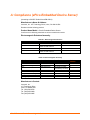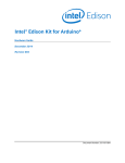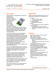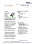
1
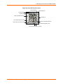
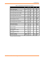
xPico Embedded Device Server Integration Guide Part Number 900-619 Revision E August 2013 Copyright and Trademark © 2013 Lantronix, Inc. All rights reserved. No part of the contents of this book may be transmitted or reproduced in any form or by any means without the written permission of Lantronix. Lantronix®, xPico® and DSTni® are registered trademarks of Lantronix, Inc. in the United States and other countries. DeviceInstaller™ is a trademark of Lantronix, Inc. Windows® is a registered trademark of Microsoft Corporation. Wi-Fi® is a registered trademark of Wi-Fi Alliance. All other trademarks and trade names are the property of their respective holders. Contacts Lantronix, Inc. 167 Technology Drive Irvine, CA 92618, USA Toll Free: 800-526-8766 Phone: 949-453-3990 Fax: 949-453-3995 Technical Support Online: www.lantronix.com/support Sales Offices For a current list of our domestic and international sales offices, go to the Lantronix web site at www.lantronix.com/about/contact Disclaimer This equipment has been tested and found to comply with the limits for a Class B digital device, pursuant to Part 15 of the FCC Rules. These limits are designed to provide reasonable protection against harmful interference in a residential installation. This equipment generates, uses, and can radiate radio frequency energy and, if not installed and used in accordance with the instructions, may cause harmful interference to radio communications. However, there is no guarantee that interference will not occur in a particular installation. If this equipment does cause harmful interference to radio or television reception, which can be determined by turning the equipment off and on, the user is encouraged to try to correct the interference by one of the following measures: 1. Reorient or relocate the receiving antenna. 2. Increase the separation between the equipment and receiver. 3. Connect the equipment into an outlet on a circuit different from that to which the receiver is connected. 4. Consult the dealer or an experienced radio/TV technician for help. This device complies with Part 15 of the FCC Rules. Operation is subject to the following two conditions: (1) This device may not cause harmful interference, and (2) this device must accept any interference received, including interference that may cause undesired operation. This device is intended only for OEM Integrators. The OEM integrator should be aware of the following important issues. xPico® Embedded Device Server Integration Guide 2 Labeling of the End Product (xPico Wi-Fi only) The label on the end product incorporating the xPico Wi-Fi module must clearly state that it contains an FCC-approved RF module. Canada and Japan also require a similar statement. For example, “This product contains RF transmitter ID # (put FCC, IC, and/or Japan module grant numbers here).” The label must include the ID numbers for the regions where the end product is installed. The grant numbers are below. xPico Wi-Fi FCC ID number: R68XPICOW xPico Wi-Fi IC ID number: 3867A-XPICOW xPico Wi-Fi Japan ID numbers: 201-135275 RSS-GEN Sections 7.1.4 and 7.1.5 Statement for Devices with Detachable Antennas (xPico Wi-Fi only) This device has been designed to operate with the antennas listed in the Certificate, and having a maximum gain of 2.88 dBi. Antennas not included in this list or having a gain greater than 2.88 dBi are strictly prohibited for use with this device, unless system level FCC approval is gained. The required antenna impedance is 50 ohms. To reduce potential radio interference to other users, the antenna type and its gain should be so chosen that the equivalent isotropically radiated power (EIRP) is not more than that required for successful communication. Integration Notes (xPico Wi-Fi): This module is authorized under limited module approval specified to mobile host equipment. So, the antenna must be installed such that 20cm is maintained between the antenna and users. The transmitter module may not be co-located with any other transmitter or antenna. As long as the two conditions above are met, further transmitter testing will not be required. However, the OEM integrator is still responsible for testing their end product for any additional compliance requirements required with this module installed (for example, digital device emission, PC peripheral requirements, etc.) In the event that these conditions cannot be met (for example certain laptop configurations, general purpose PCMCIA or similar cards, or co-location with another transmitter) and obtaining a separate FCC authorization will be required, then the FCC authorization is no longer considered valid and the FCC ID cannot be used on the final product (including the transmitter). Changes or modifications to this device not explicitly approved by Lantronix will void the user's authority to operate this device. Note: With the purchase of any xPico family product, the OEM agrees to an OEM firmware license agreement that grants the OEM a non-exclusive, royalty-free firmware license to use and distribute the binary firmware image provided, only to the extent necessary to use the xPico hardware. For further details, please see the xPico OEM firmware license agreement. Warranty For details on the Lantronix warranty policy, please go to our Web site at www.lantronix.com/support/warranty. xPico® Embedded Device Server Integration Guide 3 Revision History Date Rev. Comments April 2012 A Initial release. September 2012 B Updated the reference schematic, mounting instructions and compliance information. January 2013 C Updated xPico pin-out diagram. July 2013 D Updated to include xPico Wi-Fi part information. August 2013 E Updated to include Japanese certification number. For the latest revision of this product document, please check our online documentation at www.lantronix.com/support/documentation. xPico® Embedded Device Server Integration Guide 4 Table of Contents Copyright and Trademark ______________________________________________ Contacts ___________________________________________________________ Disclaimer __________________________________________________________ Warranty ___________________________________________________________ Revision History _____________________________________________________ List of Figures _______________________________________________________ List of Tables ________________________________________________________ 1. Introduction 2 2 2 3 4 6 6 8 About the Integration Guide ____________________________________________ 8 Additional Documentation ______________________________________________ 8 2. Functional Description xPico Features _____________________________________________________ xPico Wi-Fi Features _________________________________________________ xPico Block Diagram _________________________________________________ xPico Wi-Fi Block Diagram ____________________________________________ PCB Interface ______________________________________________________ Mating Connector ___________________________________________________ Antenna Interface (xPico Wi-Fi Only) ____________________________________ Antenna Placement (xPico Wi-Fi only) ___________________________________ Ethernet Interface (xPico wired only) ____________________________________ Serial Interface _____________________________________________________ USB Device Port (xPico Wi-Fi only) _____________________________________ LEDs _____________________________________________________________ General Purpose I/O Pins _____________________________________________ Reset Pins _________________________________________________________ Evaluation Board Schematics __________________________________________ 3. Mounting Instructions and PCB Footprint 10 11 11 13 14 15 19 19 21 21 23 24 25 26 26 27 32 To Access CAD Files ________________________________________________ 32 To Install the xPico or xPico Wi-Fi Module ________________________________ 33 Product Information Label _____________________________________________ 36 4. Specifications 38 Electrical Specifications ______________________________________________ 38 Technical Specifications ______________________________________________ 40 A: Compliance (xPico Embedded Device Server) 43 B: Compliance (xPico Wi-Fi Embedded Device Server) 44 xPico® Embedded Device Server Integration Guide 5 List of Figures Figure 2-1 xPico and xPico Wi-Fi Dimensions and Views ____________________ Figure 2-2 xPico Block Diagram _______________________________________ Figure 2-3 xPico Wi-Fi Block Diagram ___________________________________ Figure 2-4 Reverse-SMA to U.FL(long) (P/N 500-180-R) ____________________ Figure 2-5 U.FL to U.FL Cable (P/N 500-181-R) ___________________________ Figure 2-6 Reverse-SMA to U.FL(short) (P/N 500-182-R) ___________________ Figure 2-7 Ethernet Connection Example (xPico wired only) _________________ Figure 2-8 Serial Port Example ________________________________________ Figure 2-9 USB Device Interface Example (xPico Wi-Fi only) _________________ Figure 2-10 Evaluation Board Schematic, Part 1 of 5 _______________________ Figure 2-11 Evaluation Board Schematic, Part 2 of 5 _______________________ Figure 2-12 Evaluation Board Schematic, Part 3 of 5 _______________________ Figure 2-13 Evaluation Board Schematic, Part 4 of 5 _______________________ Figure 2-14 Evaluation Board Schematic, Part 5 of 5 _______________________ Figure 3-1 White Mounting Quick Clip Dimensions _________________________ Figure 3-2 Aligning Mounting Clip Legs to Standoff Holes ___________________ Figure 3-3 Mounting Instructions for PEM Standoff _________________________ Figure 3-4 Hirose Connector Layout ____________________________________ Figure 3-5 xPico Product Label ________________________________________ Figure 3-6 xPico Wi-Fi Product Label ____________________________________ 12 13 14 20 20 20 22 23 25 27 28 29 30 31 32 34 35 36 36 37 List of Tables Table 1-1 xPico and xPico Wi-Fi Features _________________________________ 8 Table 2-1 xPico Part Numbers _________________________________________ 10 Table 2-2 xPico and xPico Wi-Fi Pin Connections _________________________ 15 Table 2-3 xPico (wired) PCB Interface Signals ____________________________ 16 Table 2-4 xPico Wi-Fi PCB Interface Signals _____________________________ 17 Table 2-5 xPico Wi-Fi External Antenna Options __________________________ 20 Table 2-6 Ethernet Interface Signals ____________________________________ 21 Table 2-7 Recommended Magnetic Modules and Combo RJ45/Magnetic Module Connectors __________________ 21 Table 2-8 xPico and xPico Wi-Fi Serial Port Signals ________________________ 23 Table 2-9 RS232 Connections (Serial Transceiver Required) ________________ 24 Table 2-10 RS422/485 Connections (Serial Transceiver Required) ____________ 24 Table 2-11 USB Host Port Signals______________________________________ 24 Table 2-12 xPico Status LED Output Signals _____________________________ 25 Table 2-13 xPico Wi-Fi Status LED Output Signals _________________________ 25 Table 2-14 Ethernet Interface xPico Serial Port Signals _____________________ 26 Table 2-15 xPico Reset Signals ________________________________________ 26 Table 4-1 Absolute Maximum Ratings ___________________________________ 38 xPico® Embedded Device Server Integration Guide 6 Table 4-2 Table 4-3 Table 4-4 Table 4-5 Table A-1 Table A-2 Table B-1 Table B-2 Table B-3 xPico Wired Recommended Operating Conditions _________________ 38 xPico WiFi Recommended Operating Conditions __________________ 39 xPico Wired Technical Specification ____________________________ 40 xPico Wi-Fi Technical Specification _____________________________ 40 Electromagnetic Emissions ___________________________________ 43 Electromagnetic Immunity ____________________________________ 43 Country Certifications _______________________________________ 44 Country Transmitter IDs _____________________________________ 44 Safety ___________________________________________________ 44 xPico® Embedded Device Server Integration Guide 7 1. Introduction About the Integration Guide This guide provides the information needed to integrate the xPico® family of products into customer-printed circuit boards. This manual is intended for engineers responsible for integrating the xPico into their product. Note: This document includes support for xPico embedded device server versions XPC100100B-01, XPC100100S-01, XPC100100K-02, XPC10010MB-01 and XPC10010MS-01, and xPico Wi-Fi embedded device server versions XPW100100B-01, XPW100100S-01 and XPW100100K-02. The sections in chapter 2 provide board schematic and layout recommendations for both xPico (wired) and xPico Wi-Fi products. Some of the sections apply to xPico (wired) only or xPico Wi-Fi only. Signals that are unused for a particular product can be left floating. If the application has the potential to use both components as a stuff option it is recommended to follow the design guide for all of the sections. The table below lists which sections are applicable to the xPico (wired) and xPico Wi-Fi products. Note: xPico (wired) refers to the Ethernet-only versions of xPico. Table 1-1 xPico and xPico Wi-Fi Features Chapter 2 Section xPico (wired) PCB Interface Mating Connector Antenna Interface Antenna Placement Ethernet Inteface Serial Inteface USB Device Port LEDs General Purpose IO Pins Reset Pins Reference Schematic X X X X X X X X xPico Wi-Fi X X X X X X X X X X Additional Documentation Visit the Lantronix Web site at www.lantronix.com/support/documentation for the latest documentation and the following additional documentation. Document Description xPico Embedded Device Server User Guide Provides information needed to configure, use, and update the xPico firmware. xPico Wi-Fi Embedded Device Server User Guide Provides information needed to configure, use, and update the xPico Wi-Fi firmware. xPico Embedded Device Server Development Kit Quick Start Provides the steps for getting the xPico up and running. xPico® Embedded Device Server Integration Guide 8 1: Introduction Document Description xPico Embedded Device Server Development Kit User Guide Provides a detailed description of the xPico evaluation kit hardware APS: Modbus Protocol User Guide Provides detailed information for installing and operating the IAP device server using our Modbus firmware. DeviceInstaller™ User Guide Provides instructions for using the Windows-based utility to configure the xPico and other Lantronix device servers. Com Port Redirector User Guide Provides information on using the Windows-based utility to create a virtual com port. xPico® Embedded Device Server Integration Guide 9 2. Functional Description Designed for quick integration with minimal engineering effort, the chip-sized xPico embedded device server provides simplicity and flexibility making it the easiest and fastest networking-enabling module on the market. xPico and xPico Wi-Fi are extremely compact networking solution that enables Ethernet or Wireless connectivity on virtually any device with a serial interface. The included industry-proven Lantronix device server application and full IP stack allow seamless remote access to device data simplifying design integration while providing robust connectivity. As one of the smallest embedded device servers in the world, xPico and xPico Wi-Fi can be utilized in designs typically intended for chip solutions. A key difference with the xPico is that there is virtually no need to write a single line of code, translating to a much lower development cost and faster time-to-market. Table 2-1 xPico Part Numbers Part Number Description XPC100100B-01 xPico Device Server Module, Extended Temp, AES Encryption, Bulk, RoHS XPC100100S-01 xPico Device Server Module, Extended Temp, AES Encryption, Sample, RoHS XPC100100K-02 xPico Device Server Module Development Kit w/ Module, RoHS XPW100100B-01 xPico Wi-Fi — IEEE 802.11 b/g/n Device Server Module, Extended Temp, Bulk, RoHS XPW100100S-01 xPico Wi-Fi — IEEE 802.11 b/g/n Device Server Module, Extended Temp, Sample, RoHS XPW100100K-01 xPico Wi-Fi — IEEE 802.11 b/g/n Device Server Development Kit w/ Module, RoHS XPC10010MB-01 xPico IAP Device Server Module, Extended Temperature, Modbus, RoHS, Bulk XPC10010MS-01 xPico IAP Device Server Module, Extended Temperature, Modbus, RoHS, Sample xPico® Embedded Device Server Integration Guide 10 2: Functional Description xPico Features The xPico device server contains Lantronix’s own DSTni® EX controller, with 256 KBytes of SRAM, 16 KBytes of boot ROM, and integrated 10/100 PHY. The xPico also contains the following: 3.3-volt serial interface 8 Configurable I/O pins All logic level I/O pins are 5V input tolerant 4-Mbit flash memory Power supply filters Reset circuit +1.8V regulator Note: xPico does not contain integrated Ethernet magnetics. An external Ethernet magnetic module and RJ45 Jack is required to interface to a standard 10/100Mbps Ethernet network. The xPico requires +3.3-volt power and is designed to operate in an extended temperature range (see technical data). xPico Wi-Fi Features The xPico Wi-Fi contains Cortex M3 ARM processor with 128KByte of SRAM and 1MByte of embedded Flash memory. The unit also includes an 802.11 b/g/n WLAN radio with a U.FL port for connection to an external antenna. The xPico Wi-Fi also contains the following: 3.3-volt serial interface 8 Configurable I/O pins All logic level I/O pins are 5V input tolerant 8-Mbit flash memory (in addition to the 1MByte CPU embedded Flash) Power supply filters Reset circuit Note: xPico Wi-Fi does not contain an integrated antenna. An external antenna is required for connection to a WLAN network. The xPico Wi-Fi requires +3.3-volt power and is designed to operate in an extended temperature range (see technical data). xPico® Embedded Device Server Integration Guide 11 2: Functional Description Figure 2-1 xPico and xPico Wi-Fi Dimensions and Views xPico® Embedded Device Server Integration Guide 12 2: Functional Description xPico Block Diagram The following drawing is a block diagram of the xPico showing the relationships of the components. Figure 2-2 xPico Block Diagram xPico® Embedded Device Server Integration Guide 13 2: Functional Description xPico Wi-Fi Block Diagram The following drawing is a block diagram of the xPico Wi-Fi showing the relationships of the components. Figure 2-3 xPico Wi-Fi Block Diagram 40 Pin Connector Interface DC Power 3.3V 3.3V Cortex M3 Processor 802.11 b/g/n Chipset Serial 1 To external processor/ logic U.FL to external antenna GPIO/SPI RESET/DEFAULTS WAKE 8 Mb Serial Flash To external LED SYSTEM LED To external USB Device USB xPico® Embedded Device Server Integration Guide 14 2: Functional Description PCB Interface The xPico has a serial interface compatible with data rates up to 921,600 bps (in highperformance mode). The serial signals (RX, TX, RTS, CTS, and all CPs) are 3.3V CMOS logic level and 5V tolerant. The serial interface pins include +3.3V, ground, and reset. The serial signals usually connect to an internal device, such as a UART. For applications requiring an external cable running with RS-232 or RS422/485 voltage levels, the xPico must interface to a serial transceiver chip. All configurable I/O pins are 3.3V CMOS logic level and 5V input tolerant. xPico requires a mating connector. Customers should layout their PCB for Hirose part number DF40C(2.0)-40DS-0.4V(51). An external Ethernet magnetic module and RJ45 is required to interface xPico to a standard 10/100Mbps Ethernet network. An external antenna attached to the xPico Wi-Fi U.FL connector is required to connect to an 802.11b/g/n wireless network. Shown below is the xPico pin connection diagram highlighting the differences between the xPico and xPico Wi-Fi. Table 2-2 xPico and xPico Wi-Fi Pin Connections Pin# xPico Wired xPico Wi-Fi 1 GND GND 3 CP8 5 Pin# xPico Wired xPico Wi-Fi 2 GND GND CP8/SPI_CS 4 LED1/LINK LED1/WLAN_LED RTS1 RTS1 6 LED0/SPEED NC 7 RXD1 RXD1 8 LED2/ACTIVITY NC 9 GND GND 10 TXD1 TXD1 11 ETX- NC 12 ETCT NC 13 ETX+ NC 14 LED3/DUPLEX(OUT) WKUP (IN) 15 GND GND 16 CTS1 CTS1 17 ERX- NC 18 ERCT NC 19 ERX+ NC 20 SYS_LED SYS_LED 21 GND GND 22 Reserved DDP 23 RXD2 RXD2 24 Reserved DDM 25 TXD2 TXD2 26 CP2/INT CP2/SPI_INT 27 CP7 CP7/SPI_SCK 28 CP3 CP3/MISO 29 +3.3V +3.3V 30 CP4 CP4/MOSI 31 +3.3V +3.3V 32 CP5 CP5 33 +3.3V +3.3V 34 CP6 CP6 35 CP1 CP1 36 DEFAULT#(IN) DEFAULT#(IN) 37 GND GND 38 EXT_RESET#(IN) EXT_RESET#(IN) 39 GND GND 40 GND GND xPico® Embedded Device Server Integration Guide 15 2: Functional Description Table 2-3 xPico (wired) PCB Interface Signals Signal Name xPico Pin # Primary Function Reset State Internal Pull-up Driver Strength Active 56K to 122K 4mA GND 1 Signal Ground GND 2 Signal Ground CP8 3 Configurable I/O Input LED1/LINK 4 Ethernet Link LED, active low Output 8mA RTS1 5 Serial ready to send/ serial transmit enable Output 2mA LED0/SPEED 6 Ethernet speed LED, active low Output 8mA RXD1 7 Serial receive data input 1 Input LED2/ACTIVITY 8 Ethernet Activity LED, active low Output 8mA GND 9 Signal Ground TXD1 10 Serial transmit data output 1 Output 2mA TX- 11 Ethernet transmit differential (neg) Output TCT 12 Ethernet transmit center tap TX+ 13 Ethernet transmit differential (pos) Output LED3/DUPLEX 14 Ethernet Duplex LED, active low Output GND 15 Signal Ground CTS1 16 Serial Clear to Send Input RX- 17 Ethernet receive differential (neg) Input RCT 18 Ethernet receive center tap RX+ 19 Ethernet receive differential (pos) Input SYSTEM_LED 20 System status LED, active high Input Active 56K to 122K GND 21 Signal Ground Reserved 22 Reserved for future use. Do not connect. RXD2 23 Serial receive data input 2 Input Active 56K to 122K Reserved 24 Reserved for future use. Do not connect. TXD2 25 Serial transmit data output 2 Output CP2/INT 26 Configurable I/O-External interrupt input Input xPico® Embedded Device Server Integration Guide Active 56K to 122K 8mA Active 56K to 122K 4mA 2mA Active 56K to 122K 4mA 16 2: Functional Description Signal Name xPico Pin # Primary Function Reset State Internal Pull-up Driver Strength CP7 27 Configurable I/O Input Active 56K to 122K 4mA CP3 28 Configurable I/O Input Active 56K to 122K 4mA 3V3 29 3.3V Input Power CP4 30 Configurable I/O Input Active 56K to 122K 4mA 3V3 31 3.3V Input Power CP5 32 Configurable I/O Input 10K 4mA 3V3 33 3.3V Input Power CP6 34 Configurable I/O Input 10K 4mA CP1 35 Configurable I/O Input Active 56K to 122K 4mA DEFAULT# 36 Unit reset to default, active low. Drive low to reset unit to default settings. Input Active 56K to 122K GND 37 Signal Ground EXT_RESET# 38 Unit hardware reset, active low. Drive low to reboot unit. Input 10K GND 39 Signal Ground GND 40 Signal Ground Table 2-4 xPico Wi-Fi PCB Interface Signals Signal Name GND xPico Pin # Primary Function Reset State Internal Pull-up /Pulldown Driver Strength 1 Signal Ground 2 Signal Ground CP8/SPI_CS 3 Configurable I/O/ SPI Chip Select Input, floating 30K to 50K 8mA LED1/WLAN_LED 4 WLAN Link, active low Input, floating 30K to 50K 8mA RTS1 5 Serial ready to send/ serial transmit enable Input, floating 30K to 50K 8mA NC 6 No Connect RXD1 7 Serial receive data input 1 Input, floating 30K to 50K NC 8 No Connect GND 9 Signal Ground TXD1 10 Serial transmit data output 1 Input, 30K to 50K GND 1 xPico® Embedded Device Server Integration Guide 8mA 17 2: Functional Description Signal Name xPico Pin # Primary Function Reset State Internal Pull-up /Pulldown Driver Strength floating NC 11 No Connect NC 12 No Connect 13 No Connect 14 System Wake Up on Rising Edge GND 15 Signal Ground CTS1 16 Serial Clear to Send NC 17 No Connect NC 18 No Connect NC 19 No Connect SYSTEM_LED 20 System status LED, active high GND NC WKUP 4 Input, floating 30K to 50K Input, floating 30K to 50K Input, floating 30K to 50K Input, floating 30K to 50K 8mA 21 Signal Ground 2 DDP 22 USB (positive) RXD2 23 Serial receive data input 2 DDM 2 24 USB Negative TXD2 25 Serial transmit data output 2 Input, floating 30K to 50K 8mA 26 Configurable I/O-External interrupt input Input, floating 30K to 50K 8mA 27 Configurable I/O/ SPI Clock Input, floating 30K to 50K 8mA 28 Configurable I/O/SPI Master In-Slave Out Input, floating 30K to 50K 8mA 29 3.3V Input Power 30 Configurable I/O/ SPI Master Out-Slave In Input, floating 30K to 50K 8mA 3V3 31 3.3V Input Power CP5 32 Configurable I/O Input, floating 30K to 50K 8mA 3V3 33 3.3V Input Power CP6 34 Configurable I/O Input, floating 30K to 50K 8mA CP1 35 Configurable I/O Input, floating 30K to 50K 8mA DEFAULT# 36 Unit reset to default, active low. Drive low to reset unit to Input, floating 30K to 50K 1 CP2/INT 1 CP7/SPI_SCK 1 CP3/MISO 3V3 CP4/MOSI 1 xPico® Embedded Device Server Integration Guide 18 2: Functional Description Signal Name xPico Pin # Primary Function Reset State Internal Pull-up /Pulldown Input 30K to 50K Driver Strength default settings. GND 37 Signal Ground EXT_RESET# 38 Unit hardware reset, active low. Drive low to reboot unit. GND 39 Signal Ground GND 40 Signal Ground Note1: The xPico Wi-Fi SPI interface can be master or slave. Note2: The xPico Wi-Fi USB interface is USB2.0 Full Speed Host/Device/OTG capable. Host/Device/OTG interface connectors and power interface must be designed into the mating board. Note3. xPico and xPico Wi-Fi may be designed into the same socket. Signals listed as no connect on xPico Wi-Fi may be connected on an xPico base design board. For example, xPico Wi-Fi pins 11, 12, 13, 17, 18, and 19 may connect to an Ethernet magnetic module as designed for xPico (wired), however, Ethernet will not be available on those pins for xPico Wi-Fi. Note 4. Pin 14 is the Ethernet duplex LED output on xPico (wired) and the system wakeup input on xPico Wi-Fi. For board designs supporting both xPico (wired) and xPico Wi-Fi, a zero ohm resistor stuff option should be used to disconnect any on-board logic driving pin 14 when xPico (wired) is installed. Note 5. The CP pins can be configured as pull-up or pull-down. The WKUP pin is not configurable and is always pull-down. Note 6. The IO pins on xPico Wi-Fi are configured as floating-input on reset until configured by firmware. For applications requiring a high signal on power up, an external pull-up may be required. Mating Connector The mating connector for the xPico and xPico Wi-Fi module is Hirose part number DF40C (2.0)-40DS-0.4V (51). Special care must be taken when mating and unmating the module to the mating connector. Refer to the Hirose DF40 data sheet below for proper connector mating and unmating, along with the proper connector footprint. Mating connector data sheet: http://www.hirose.co.jp/cataloge_hp/e68440018.pdf Antenna Interface (xPico Wi-Fi Only) The xPico Wi-Fi module has been certified using the external antennas listed below. Per FCC guidelines, the xPico Wi-Fi certification remains valid if using an antenna of similar type to the antennas below. If using an antenna of similar type to one of the antennas below, but from a different manufacturer part number the antenna gain must be equal to or less than specified in the table. Consult with your certification lab for more details. xPico® Embedded Device Server Integration Guide 19 2: Functional Description Table 2-5 xPico Wi-Fi External Antenna Options Antenna Type Peak Gain Typical Lantronix Part Number Vendor Vendor Part Number PCB Strip Antenna with cable to U.FL connector Swivel type antenna, with RP-SMA(M) connector 1.5 to 2.5dBi, 2.39 Ghz to 2.49 Ghz 2 dBi, 2.4 Ghz to 2.5 Ghz, 2 dBi, 5.15 Ghz to 5.85 Ghz 930-099-R Ethertronics 1000668 930-033-R Wanshih WSS002 Lantronix provides a U.FL to Reverse SMA antenna cable in with the evaluation board and sample kits for development work. These cables can be purchased from Lantronix for production or supplied by an RF cable manufacturer. External antennas can be purchased from the antenna vendor. Components for cable design should be selected for low loss over the entire 2.4Ghz to 5.9Ghz signal range. The cable target impedence should be 50 ohms. Figure 2-4 Reverse-SMA to U.FL(long) (P/N 500-180-R) Figure 2-5 U.FL to U.FL Cable (P/N 500-181-R) Figure 2-6 Reverse-SMA to U.FL(short) (P/N 500-182-R) xPico® Embedded Device Server Integration Guide 20 2: Functional Description Antenna Placement (xPico Wi-Fi only) When designing the xPico Wi-Fi module to a mating board, it is important to consider the final installation of the unit and its location with respect to connecting access points. The antenna should be placed so that it has as clear as possible path to the connecting access point for maximum range. Avoid placing the antenna such that it is blocked by metal walls or ground planes of adjacent circuit boards. Ethernet Interface (xPico wired only) xPico integrates an internal 10/100Mbps Ethernet MAC and PHY. An external magnetic module and RJ45 is required in order to connect to a standard 10/100Mbps Ethernet network. Table 2-6 Ethernet Interface Signals Signal Name DIR Contact Primary Function Signal Requirement TX+ Out 13 Differential Ethernet transmit data + 100 ohm differential with TX- TX- Out 11 Differential Ethernet transmit data - 100 ohm differential with TX+ RX+ In 19 Differential Ethernet receive data + 100 ohm differential with RX- RX- In 17 Differential Ethernet receive data - 100 ohm differential with RX+ TCT 12 Ethernet transmit center tap connection Route > 20 mil width RCT 18 Ethernet receive center tap connection Route > 20 mil width The xPico provides a 10/100 Mbps Ethernet interface for connection to an external network through external magnetics and an external RJ45. The table below lists several magnetic modules and combination RJ45/magnetic jacks that can be used with xPico. Table 2-7 Recommended Magnetic Modules and Combo RJ45/Magnetic Module Connectors Type Manufacturer Part Number Magnetic only (requires RJ45) BI-Tech HS91-011-80LFTR Magnetic only (requires RJ45) Mingtek HN0013SG Combination RJ45/Magnetic Belfuse 08B0-1D1T-06-F Combination RJ45/Magnetic Midcom MIC2411D-0117T-LF3 Magnetic for POE PULSE HX2019 The Ethernet differential pair signals, ERX-/ERX+ and ETX-/ETX+ should be routed as 100-ohm differential pairs on a layer next to the signal ground plane. The use of vias on these signals should be minimized. The center tap signal connections between the magnetic and xPico (wired) module are required. Center tap signals RCT and TCT should be routed with at least 20 mil trace thickness. The area between the magnetic module and RJ45 jack, including the area under both, should be voided of all signals and xPico® Embedded Device Server Integration Guide 21 2: Functional Description planes, except for the signals connecting to both. The signals connecting between the RJ45 and magnetic are required to be isolated by 1500Vrms from all other signals and planes, including chassis and signal ground. The connector shield should be connected to chassis. It is recommended that 1206 resistor pads from chassis ground to signal ground be placed next to each of the shield tabs. The resistor pads allow for 0 ohm jumper, ferrite beads, or decoupling caps to be installed as needed for EMI/EMC improvement. The Ethernet LED signals should be routed to discrete LEDs or to the LED pins on the RJ45 through 220 ohm or larger resistors. The LED signals are active low. The Ethernet LED signals should be isolated from the signals that connect between the RJ45 and magnetic module. Also shown in the reference schematic is a recommended TVS array that can be used to improve ESD and EFT in harsh environments. The device shown is Semtec RCIamp0502A. This device features route through pin assignments allowing for the Ethernet differential signal pairs to be routed without altering the trace impedance or adding vias. Due to this routing, the device could be installed or depopulated as needed. See the Lantronix app note, How to Connect a Lantronix Embedded Module to a Wired Ethernet Port for more details on Ethernet connection and routing, http://www.lantronix.com/pdf/appnotes/Connect-LTRX-Embed-Module-to-WiredEthernet_AN.pdf. The xPico module can also be powered from POE using a POE magnetic and POE powered device controller. Lantronix uses the Silabs, Si3402 POE controller to power the xPico development board via POE. If using POE the Ethernet magnetic module should be changed to a POE compatible module such as Pulse HX2019. Refer to the evaluation board schematic in the xPico-DevKit_UG for an example circuit. http://www.lantronix.com/pdf/xPico-DevKit_UG.pdf. Refer to the SiLabs data sheet for Si3402 for more information on using the SiLabs POE controller. Figure 2-7 Ethernet Connection Example (xPico wired only) xPico® Embedded Device Server Integration Guide 22 2: Functional Description Serial Interface The xPico and xPico Wi-Fi have two external serial interfaces. The signal levels on the serial interface are 3.3V logic level with 5V tolerant inputs. The serial interfaces require an external transceiver in order to connect to external RS232, RS485, or RS422 networks. The signals of Serial Port 1 may be connected as shown in the reference schematic, Figure 2-8 Serial Port Example, below. The transceiver shown in the reference schematic is of type Exar, part number SP336. This transceiver is a multiprotocol RS232, RS485, RS422 transceiver. Single protocol transceivers may be used as required. The xPico interface may also be directly connected to the UART interface of an external CPU. Serial Port 2 is a three wire interface only. It operates like Serial Port 1, except it does not support hardware Flow Control (i.e. no RTS/CTS) and modem control (i.e. no DTR/DCD). Table 2-8 xPico and xPico Wi-Fi Serial Port Signals Signal Pin Description Reset State TXD1 10 Serial Transmit Data output Output RTS1 5 Serial Ready-to-Send / Serial Transmit enable Output RXD1 7 Serial Receive Data input Input CTS1 16 Serial Clear-to-Send Input TXD2 25 Serial Transmit Data output 2 Output RXD2 23 Serial Receive Data input 2 Input Figure 2-8 Serial Port Example xPico® Embedded Device Server Integration Guide 23 2: Functional Description Table 2-9 RS232 Connections (Serial Transceiver Required) xPico Signal DCE Connector DTE Connector Signal (Logic) RXDx TXDx RTSx CTSx CPx CPy Description DB9 DB25 Signal DB9 DB25 Signal Data In Data Out H/W Flow Control Output H/W Flow Control Input Modem Control Input Modem Control Output 2 3 7 8 1 4 3 2 4 5 8 20 RXDx TXDx RTSx CTSx DCDx DTRx 3 2 8 7 4 1 2 3 5 4 20 8 TXDx RXDx CTSx RTSx DTRx DCDx Table 2-10 RS422/485 Connections (Serial Transceiver Required) xPico Signal (logic) Description RS485 Signal DB25 4 Wire DB25 2 Wire DB9 4 wire DB9 2 wire TXDx TXDx RXDx RXDx RTSx CPx CPy Data Out Data Out Data In Data In TX Enable RS485 Select RS485 2-wire TX+485 TX-485 RX+485 RX-485 14 15 21 22 14 15 14 15 7 3 2 8 7 3 7 3 Note: The IO pins for xPico Wi-Fi are set to floating input on power up until configured by unit firmware. An external 100K ohm pull-up may be required on the serial transmit signal to prevent downstream UART devices from detecting false characters on initial power up. USB Device Port (xPico Wi-Fi only) The xPico Wi-Fi has one USB2.0 Full Speed Device port interfaces for connection to an upstream USB device. The port consists of a differential pair, signals DDP and DDM. These signals should be routed as a 90 ohm differential pair on a signal layer next to the signal ground plane. The use of vias should be minimized on these signals. The USB signals can be connected to a USB Mini Type B USB port (as shown in Table 2-12) directly to an IC with a USB host port. If connecting to an external port that is user accessible it is recommended to add a TVS diode array to the signal nets for ESD protection. The ESD array shown in the figure is of type Semtech RCIamp0502A. This device features through pin routing to minimize trace impedance changes and simplify routing. The footprint for the TVS array can be added to the PCB and the part can be depopulated if it is not needed. It is recommended that the power drawn off the USB Mini Type B connector be limited to less than 500mA per USB requirements. If the USB device port is unused the DDP and DDM pins may be left unconnected. Table 2-11 USB Host Port Signals Pin Name Description Connector Pins Signal Requirement Mini Type B USB Device connector pin DDP USB Device Port Positive pin 22 Route as 90 ohm differential pair with DDM signal 3 xPico® Embedded Device Server Integration Guide 24 2: Functional Description Pin Name Description Connector Pins Signal Requirement Mini Type B USB Device connector pin DDM USB Device Port Negative pin 24 Route as 90 ohm differential pair with DDP signal 2 5V 5V power from USB cable Current limit to 500 mA per port 1 Ground Signal Ground Ground plane 5 Ground Figure 2-9 USB Device Interface Example (xPico Wi-Fi only) LEDs The xPico contains several external signals that are intended to drive external status LEDs. The LEDs are listed below. The signals may be connected as shown in the reference schematic figure below. Table 2-12 xPico Status LED Output Signals Signal Pin Description LED1/WI-FI LED 4 WI-FI Status LED, active low SYSTEM_LED 20 System status LED, active high Table 2-13 xPico Wi-Fi Status LED Output Signals Signal Pin Description LED0/SPEED 6 Ethernet speed LED, active low LED1/LINK 4 Ethernet Link LED, active low LED2/ACTIVITY 8 Ethernet Activity LED, active low LED3/DUPLEX 14 Ethernet Duplex LED, active low SYSTEM_LED 20 System status LED, active high xPico® Embedded Device Server Integration Guide 25 2: Functional Description General Purpose I/O Pins xPico and xPico Wi-Fi contains eight pins which may be used as configurable inputs or outputs. Listed below are the configurable I/O pins. These pins are 3.3V CMOS logic level and 5V input tolerant. Table 2-14 Ethernet Interface xPico Serial Port Signals Signal Pin Description xPico Wired Description xPico Wi-Fi Reset State CP1 35 Configurable I/O Configurable I/O Input CP2/INT 26 Configurable I/O-External interrupt input Configurable I/O-SPI interrupt input Input CP3 28 Configurable I/O Configurable I/O- SPI MISO Input CP4 30 Configurable I/O Configurable I/O-SPI MOSI Input CP5 32 Configurable I/O Configurable I/O Input CP6 34 Configurable I/O Configurable I/O Input CP7 27 Configurable I/O Configurable I/O-SPI Clock Input CP8 3 Configurable I/O Configurable I/O-SPI Chip Select Input Note 1. For xPico Wi-Fi 5V tolerant pins, in order to sustain a voltage higher than Vcc+0.3, the internal pull-up/ pull-down resistors must be disabled. Reset Pins xPico and xPico Wi-Fi have two signals for use as reset signals. Signal EXT_RESET# is a hardware controlled input signal that will reboot the xPico processor when asserted low. Signal DEFAULT# is polled by the xPico software. When DEFAULT# is asserted low for six seconds, the unit will reset the system to the default manufacturing settings and reboot the unit. xPico Wi-Fi has an additional signal on pin 14 that can be used to wake up the unit processor when the unit is in a sleep or power down state. Table 2-15 xPico Reset Signals Signal Pin Description Reset State Internal pull-up EXT_RESET# 38 Unit hardware reset, active low. Drive low to reboot unit. Input 10K (xPico) 40K (xPico Wi-Fi) DEFAULT# 36 Unit reset to default, active low. Drive low to reset unit to default settings. Input Active 56K to 122K (xPico) 40K (xPico Wi-Fi) WAKE (xPico Wi-Fi only) 14 Toggle signal from low to high to WAKE from SLEEP or Power down state Input 40K xPico® Embedded Device Server Integration Guide 26 2: Functional Description Evaluation Board Schematics Figure 2-10 Evaluation Board Schematic, Part 1 of 5 xPico® Embedded Device Server Integration Guide 27 2: Functional Description Figure 2-11 Evaluation Board Schematic, Part 2 of 5 xPico® Embedded Device Server Integration Guide 28 2: Functional Description Figure 2-12 Evaluation Board Schematic, Part 3 of 5 xPico® Embedded Device Server Integration Guide 29 2: Functional Description Figure 2-13 Evaluation Board Schematic, Part 4 of 5 xPico® Embedded Device Server Integration Guide 30 2: Functional Description Figure 2-14 Evaluation Board Schematic, Part 5 of 5 xPico® Embedded Device Server Integration Guide 31 3: Mounting Instructions and PCB Footprint 3. Mounting Instructions and PCB Footprint The xPico embedded device server dimensions and mounting instructions are shown in the following drawings below. You may also directly access the CAD files through the Lantronix website. Note: The mounting instructions in this section are applicable to both the xPico and the xPico Wi-Fi Embedded Device Servers though the xPico pictures below are used to demonstrate installation. For temperature environments up to +85° Celsius, it is recommended that the mating PCB have its outer layers flooded with signal ground and a heat pad be placed between the module and mating PCB. The recommended heat pad is Lantronix part number XPC100A002-01-B. The ground flooding and heat pad are only required for xPico Wi-Fi in environments above +70°C. For environments below +70°C the heat pad and ground flooding are not required. To Access CAD Files 1. Go to http://www.lantronix.com/products/cad-visio.html. 2. Click Download CAD files here to access the Registration Form. Figure 3-1 White Mounting Quick Clip Dimensions xPico® Embedded Device Server Integration Guide 32 3: Mounting Instructions and PCB Footprint To Install the xPico or xPico Wi-Fi Module In the xPico Development Kit (Part Number XPC100100K-02) and xPico Wi-Fi Development Kit (XPW100100K-01), the xPico module comes installed to the xPico Evaluation Board via the connector J1 (Hirose component). If ordered separately, you may need to install it by following the directions below. The included white Mounting Quick Clip is used to align and fasten the module to the evaluation board. 1. Place the module into the white mounting clip, lining up the clip legs and the four module grooves so that the module is seated inside the white clip. For xPico Wi-Fi connect the RF cable to the module U.FL connector prior to installing the Quick Clip. White Mounting Clip xPico/xPico Wi-Fi Module 2. Push the legs of the white clip inward to secure the module to the clip. Module/Mounting Clip Combination 3. Flip over the module/mounting clip combination so that the product label displays on top and the white mounting clip legs are pointed downward. 4. For XPico Wi-Fi high temperature operation, above +70C, it is recommended to place a heat pad between the module and the adjacent PCB. The recommended heat pad is Lantronix part number XPC100A002-01-B (available in a 50 piece bulk pack). 5. Place the module/mounting clip combination so that the four mounting clip legs align with the four standoff holes on the board surrounding the J1 connector (see Figure 3-2). Make sure to properly orientate the module/mounting clip combination on the board, so that the J1 connector/Hirose component is properly aligned. xPico® Embedded Device Server Integration Guide 33 3: Mounting Instructions and PCB Footprint Figure 3-2 Aligning Mounting Clip Legs to Standoff Holes 6. Insert the white clip legs furthest from the J1 connector first and gently push down on the xPico module above the J1 connector. Keep the module as level as possible during installation. Note: When removing the xPico from the evaluation board, gently tug the module. Do not use excessive force or attempt to remove the xPico module by grasping and pulling the module from the short end opposite the module connector as this may cause damage to the J1 evaluation board connector. xPico® Embedded Device Server Integration Guide 34 3: Mounting Instructions and PCB Footprint Figure 3-3 Mounting Instructions for PEM Standoff xPico® Embedded Device Server Integration Guide 35 3: Mounting Instructions and PCB Footprint Figure 3-4 Hirose Connector Layout Product Information Label The product information label contains important information about your specific unit, such as its part number, revision, manufacturing date code, product model, country of origin, datamatrix barcode and MAC address. Figure 3-5 xPico Product Label Part Number Revision MAC Address Manufacturing Date Code Product Model Country of Origin xPico® Embedded Device Server Integration Guide Lantronix Datamatrix Barcode 36 3: Mounting Instructions and PCB Footprint Figure 3-6 xPico Wi-Fi Product Label Revision Number Canada Radio ID Product Model Part Number Japan Certification Number FCC Radio ID Japan Radio Equipment Mark Lantronix Datamatrix Barcode Japan Telecommunication Mark Manufacturing Date Code Serial Number xPico® Embedded Device Server Integration Guide Country of Origin 37 4: Specifications 4. Specifications Electrical Specifications Caution: Stressing the device above the rating listed in this table may cause permanent damage to the xPico embedded device server. Exposure to Absolute Maximum Rating conditions for extended periods may affect the xPico’s reliability. For xPico Wi-Fi operation above +70° Celsuis, it is recommended that a heat pad be placed between the module and mating PCB. Table 4-1 Absolute Maximum Ratings Parameter Symbol Min Max Units Supply Voltage VCC 0 3.6 Vdc Operating Temperature -40 85 °C Storage Temperature -40 85 °C Table 4-2 xPico Wired Recommended Operating Conditions Parameter Symbol Min Typical Max Units Supply Voltage VCC 3.15 3.3 3.46 Vdc Supply Voltage Ripples VCC_PP 2 % 100 BaseTX Active (Normal CPU Speed) 10 BaseT Active (Normal CPU Speed) No Link (Normal CPU Speed) 100 BaseTX Active (High CPU Speed) 10 BaseT Active (High CPU Speed) No Link (High CPU Speed) 100 BaseTX Active (Low CPU Speed) 10 BaseT Active (Low CPU Speed) ICC 200 mA ICC 220 mA ICC 150 mA ICC 240 mA ICC 260 mA ICC 190 mA ICC 170 mA mA mA ICC 190 No Link (Low CPU Speed) ICC 120 Supply Reset Threshold VRST 2.7 CPx Pull-ups, except CP5, CP6 RPU 56 CP5,CP6 Pull-up RPU CPx, RX Input Low Voltage VCP_IL CPx, RX Input High Voltage VCP_IH CPx, TX Output Low Voltage (IOL = 4 mA) VCP_OL CPx, TX Output High Voltage (IOH = -4 mA) VCP_OH Reset Pin Low Voltage VRES_IL Reset Pin High Voltage VRES_IL xPico® Embedded Device Server Integration Guide Vdc 122 10 2 Kohm 0.8 Vdc 5.5 Vdc 0.4 Vdc 2.4 2.0 Kohm Vdc 0.36 Vdc 3.46 Vdc 38 4: Specifications Table 4-3 xPico WiFi Recommended Operating Conditions Parameter Symbol Min Typical Max Units Supply Voltage VCC 3.15 3.3 3.46 Vdc Supply Voltage Ripples VCC_PP TX Power @ 16.5dBm, 802.11b, 11Mbps TX Power @ 15dBm, 802.11g, 6Mbps TX Power @ 13dBm, 802.11g, 54Mbps TX Power @ 14.5dBm, 802.11n, MCS0 TX Power @ 12dBm, 802.11n, MCS7 RX Power @ 802.11b, 11Mbps 2 % ICC 330 380 mA ICC 300 345 mA ICC 255 295 mA ICC 290 335 mA ICC 230 265 mA 150 mA ICC 125 RX Power @ 802.11g, 54Mbps ICC 125 150 mA RX Power @ 802.11n, MCS7 ICC 125 150 mA Power Management State 1 @ 25°C ICC 6 μA Power Management State 1 @ +85°C ICC 12 μA Power Management State 1 @ -40°C ICC 5 μA Supply Reset Threshold VRST CPx Pull-ups/ Pull-downs RPU 30 CPx, RX Input Low Voltage VCP_IL CPx, RX Input High Voltage VCP_IH CPx, TX Output Low Voltage (IOL = 4 mA) VCP_OL CPx, TX Output High Voltage (IOH = -4 mA) VCP_OH 2.4 Reset Pin Low Voltage VRES_IL -0.3 0.8 Vdc Reset Pin High Voltage VRES_IL 2 Vcc+0.3 Vdc (1) Vdc 40 50 Kohm -0.3 0.75 Vdc 2 5.5 Vdc 0.4 Vdc Vdc Note 1. For xPico Wi-Fi 5V tolerant pins, in order to sustain a voltage higher than Vcc+0.3, the internal pullup/pull-down resistors must be disabled. xPico® Embedded Device Server Integration Guide 39 4: Specifications Technical Specifications Table 4-4 xPico Wired Technical Specification Category Description CPU, Memory Lantronix DSTni-EX 186 CPU, 256-Kbyte zero wait state SRAM, 512Kbyte flash, 16-Kbyte boot ROM Firmware Upgradeable via TFTP and serial port Reset Circuit Internal 200ms power-up reset pulse. Power-drop reset triggered at 2.6V. External reset input causes an internal 200ms reset. Serial Interface CMOS (Asynchronous) 3.3V-level signals Rate is software selectable: 300 bps to 921600 bps Serial Line Formats Data bits: 7 or 8 Stop bits: 1 or 2 Parity: odd, even, none Modem Control DTR/DCD, CTS, RTS <- Serial 1 only Flow Control Serial 1: XON/XOFF (software), CTS/RTS (hardware) Serial 2: XON/XOFF (software) Programmable I/O 8 PIO pins (software selectable), sink or source 4mA max. Network Interface 10/100Mbps Ethernet, requires external magnetics and RJ45 Compatibility Ethernet: Version 2.0/IEEE 802.3 (electrical), Ethernet II frame type Protocols Supported ARP, UDP/IP, TCP/IP, Telnet, ICMP, SNMP, DHCP, BOOTP, TFTP, Auto IP, SMTP, and HTTP LEDs Link, Activity, Link Speed, Duplex, System Status logic level outputs Management Internal web server, SNMP (read only) Serial login, Telnet login Security Password protection, locking features, optional Rijndael 256-bit encryption Internal Web Server Serves static Web pages and Java applets Storage capacity: 384 Kbytes Weight 2.5 grams Material Metal shell Temperature Operating range: -40°C to +85°C (-40°F to 185°F) Warranty For details on the Lantronix warranty policy, go to our web site at www.lantronix.com/support/warranty. Included Software Windows™ 98/NT/2000/XP-based Device Installer configuration software and Windows™-based Com Port Redirector EMI Compliance See A:Compliance. Table 4-5 xPico Wi-Fi Technical Specification Category Description CPU, Memory Cortex M3 CPU, 1MB Flash, 128KB+4KB SRAM, Additional 1MB on board Flash Firmware Upgradeable via TFTP and serial port WLAN Standards 802.11 b/g/n Wireless LAN with external antenna Antenna Connector U.FL connector for external antenna Frequency Band 2.400Ghz to 2.484Ghz xPico® Embedded Device Server Integration Guide 40 4: Specifications Category Description Channel Support Channel 1 to Channel 14 Modulation DSSS, CCK, OFDM, BPSK, QPSK, 16QAM, 64QAM Protocols Supported ARP, UDP/IP, TCP/IP, Telnet, ICMP, SNMP, DHCP, BOOTP, TFTP, Auto IP, SMTP, and HTTP Data Rates 802.11b 1, 2, 5.5, 11 Mbps Data Rates 802.11g 6, 9, 12, 18, 24, 36, 48, 54 Mbps Date Rates 802.11n HT20 MCS0 (6.5Mbps) to HT20 MCS7 (65Mbps) 802.11b, CCK Mode Average Output Power 16.5 +/- 1.5dBm Typical @ 25C 802.11g, OFDM Mode Average Output Power 15 +/- 1.5dBm, Typical @ 25C, 6Mbps 13 +/- 1.5dBm, Typical @ 25C, 54Mbps 802.11n, OFDM Mode Average Output Power 14.5 +/- 1.5dBm, Typical @ 25C, MCS0 12 +/- 1.5dBm, Typical @ 25C, MCS7 802.11b Average Output EVM IEEE Spec -10dBm 802.11g Average Output EVM IEEE Spec, -5dB @ 6Mbps IEEE Spec, -25dB @ 54Mbps 802.11n Average Output EVM IEEE Spec, -5dB @ MCS0 IEEE Spec, -28dB @ MCS7 802.11b, PER <8% RX Sensitivity @ 1Mbps -93dBm Typical -89dBm Max 802.11b, PER <8% RX Sensitivity @ 11Mbps -88dBm Typical -84dBm Max 802.11g, PER <10% RX Sensitivity @ 6Mbps -87dBm Typical -83dBm Max 802.11g, PER <10% RX Sensitivity @ 54Mbps -74dBm Typical -70dBm Max 802.11n, PER <10% RX Sensitivity @ MCS0 -87dBm Typical -83dBm Max 802.11n, PER <10% RX Sensitivity @ MCS7 -71dBm Typical -67dBm Max Serial Interface CMOS (Asynchronous) 3.3V-level signals Rate is software selectable: 300 bps to 921600 bps Serial Line Formats Data bits: 7 or 8 Stop bits: 1 or 2 Parity: odd, even, none Modem Control DTR/DCD, CTS, RTS <- Serial 1 only Flow Control Serial 1: XON/XOFF (software), CTS/RTS (hardware) Serial 2: XON/XOFF (software) Programmable I/O 8 PIO pins (software selectable), sink or source 4mA max. LEDs WLAN Status, System Status logic level outputs Management Internal web server, SNMP (read only) Serial login, Telnet login Security Password protection, locking features, optional Rijndael 256-bit encryption Internal Web Server Serves static Web pages and Java applets Storage capacity: TBD Kbytes Weight 2.5 grams Material Metal shell xPico® Embedded Device Server Integration Guide 41 4: Specifications Category Description Temperature Operating range: -40°C to +85°C (-40°F to 185°F) with use of heat pad between module and mating PCB Warranty For details on the Lantronix warranty policy, go to our web site at www.lantronix.com/support/warranty. Included Software Windows™ 98/NT/2000/XP-based Device Installer configuration software and Windows™-based Com Port Redirector EMI Compliance See A:Compliance. xPico® Embedded Device Server Integration Guide 42 A: Compliance (xPico Embedded Device Server) (According to ISO/IEC Guide 22 and EN 45014) Manufacturer’s Name & Address: Lantronix, Inc. 167 Technology Drive, Irvine, CA 92618 USA Declares that the following product: Product Name Model: xPico® Embedded Device Server Conforms to the following standards or other normative documents: Electromagnetic Emissions/Immunity: Table A-1 Electromagnetic Emissions Test Description Specification Test Method Radiated Emissions Radiated Emissions EN 55022:2010 Class B FCC 15.109(g):2012 CISPR 22:1997 Class B EN 55022:2010 Class B FCC 15.109(g):2012 CISPR 22:1997 Class B CISPR 22:2008 ANSI C63.4:2009 Conducted Emissions Conducted Emissions CISPR 22:2008 ANSI C63.4:2009 Table A-2 Electromagnetic Immunity Test Description Specification Test Method Performance Criteria ESD Radiated Immunity EFT EN 55024:2010 EN 55024:2010 EN 55024:2010 2 1 1 Surge Conducted Immunity Magnetic Field Immunity Voltage Interruptions Voltage Dips EN 55024:2010 EN 55024:2010 EN 55024:2010 EN 55024:2010 EN 55024:2010 IEC 61000-4-2:2008 IEC 61000-4-3:2010 IEC 61000-4-4:2004 (Amended by A1:2010) IEC 61000-4-5:2005 IEC 61000-4-6:2008 IEC 61000-4-8:2009 IEC 61000-4-11:2004 IEC 61000-4-11:2004 1 1 1 3 1 Manufacturer’s Contact: Lantronix, Inc. 167 Technology Drive Irvine, CA 92618 USA Tel: (800) 526-8766 Tel: (949) 453-3990 Fax: (949) 453-3995 xPico® Embedded Device Server Integration Guide 43 B: Compliance (xPico Wi-Fi Embedded Device Server) (According to ISO/IEC Guide 22 and EN 45014) Manufacturer’s Name & Address: Lantronix, Inc. 167 Technology Drive, Irvine, CA 92618 USA Declares that the following product: Product Name Model: xPico® Wi-Fi® Embedded Device Server Conforms to the following standards or other normative documents: Country Wireless Certifications Table B-1 Country Certifications Country Specification USA FCC Part 15, Subpart B, Class B ICES-003:2012 Issue 5, Class B ANSI C63.4-2009 FCC Part 15, Subpart C (Section 15.247) ANSI C63.10-2009 FCC Part 2 (Section 2.1091) FCC OET Bulletin 65, Supplement C (01-01) IEEE C95.1 Canada RSS-210 Issue 8 (2010-12) Canada RSS-Gen Issue 3 (2010-12) ANSI C63.10-2009 RSS-102 Issue 4 (2010-12) EN 300 328 V1.8.1 (2012-06) EN 301 489-1 V1.9.2 (2011-09) EN 301 489-17 V2.2.1 (2012-09) EN 55022:2010+AC:2011, Class B EN62311:2008 AS/NZS 4268: 2012 ARIB STD-T66, MIC notice 88 Appendix 43 RCR STD-33, MIC notice 88 Appendix 44 USA Canada EU Australia, New Zealand N11206 Japan Table B-2 Country Transmitter IDs Country Specification USA FCC ID Canada IC ID Japan ID R68XPICOW 3867A-XPICOW 201-135275 Table B-3 Safety Country Specification World Wide CB EN 60950-1:2006 + A11:2009 + A1:2010 + A12:2011 In accordance with the council directive 2006/95/EC UL 60950-1 (2nd Edition) US, Canada xPico® Embedded Device Server Integration Guide 44 Manufacturer’s Contact: Lantronix, Inc. 167 Technology Drive Irvine, CA 92618 USA Tel: (800) 526-8766 Tel: (949) 453-3990 Fax: (949) 453-3995 ROHS Notice All Lantronix products in the following families are China RoHS-compliant and free of the following hazardous substances and elements: • Lead (Pb) • Cadmium (Cd) Product Family Name UDS1100 and 2100 EDS MSS100 IntelliBox xPress DR & sPress-DR+ SecureBox 1101 & 2101 WiBox UBox MatchPort SLC xPort xPort Pro WiPort SLB SLP SCS SLS DSC PremierWave Micro125 xPico xPico Wi-Fi xPrintServer • • Mercury (Hg) • Hexavalent Chromium (Cr (VI)) • Toxic or hazardous Substances and Elements Lead Mercury Cadmium Hexavalent (Pb) (Hg) (Cd) Chromium (Cr (VI)) 0 0 0 0 0 0 0 0 0 0 0 0 0 0 0 0 0 0 0 0 0 0 0 0 0 0 0 0 0 0 0 0 0 0 0 0 0 0 0 0 0 0 0 0 0 0 0 0 0 0 0 0 0 0 0 0 0 0 0 0 0 0 0 0 0 0 0 0 0 0 0 0 0 0 0 0 0 0 0 0 0 0 0 0 0 0 0 0 0 0 0 0 Polybrominated biphenyls (PBB) Polybrominated diphenyl ethers (PBDE) Polybrominated biphenyls (PBB) 0 0 0 0 0 0 0 0 0 0 0 0 0 0 0 0 0 0 0 0 0 0 0 Polybrominated diphenyl ethers (PBDE) 0 0 0 0 0 0 0 0 0 0 0 0 0 0 0 0 0 0 0 0 0 0 0 O: toxic or hazardous substance contained in all of the homogeneous materials for this part is below the limit requirement in SJ/T11363-2006. X: toxic or hazardous substance contained in at least one of the homogeneous materials used for this part is above the limit requirement in SJ/T11363-2006. xPico® Embedded Device Server Integration Guide 45