1
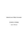
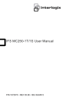
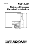
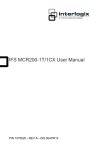
IFS MCR200-1T-1TW User Guide P/N 1072685 • REV A • ISS 30OCT13 Copyright © 2013 United Technologies Corporation Interlogix is part of UTC Climate Controls & Security, a unit of United Technologies Corporation. All rights reserved. Trademarks and patents The IFS MCR200-1T-1TW name and logo are trademarks of United Technologies. Other trade names used in this document may be trademarks or registered trademarks of the manufacturers or vendors of the respective products. Manufacturer Interlogix 3211 Progress Drive, Lincolnton, NC 28092 USA Authorized EU manufacturing representative: UTC Climate Controls & Security B.V., Kelvinstraat 7, 6003 DH Weert, Netherlands Version Certification FCC compliance ACMA compliance This document applies to IFS MCR200-1T-1TW version 1.0. N4131 Class A: This equipment has been tested and found to comply with the limits for a Class A digital device, pursuant to part 15 of the FCC Rules. These limits are designed to provide reasonable protection against harmful interference when the equipment is operated in a commercial environment. This equipment generates, uses, and can radiate radio frequency energy and, if not installed and used in accordance with the instruction manual, may cause harmful interference to radio communications. Operation of this equipment in a residential area is likely to cause harmful interference in which case the user will be required to correct the interference at his own expense. Notice! This is a Class A product. In a domestic environment this product may cause radio interference in which case the user may be required to take adequate measures. Canada European Union directives This Class A digital apparatus complies with Canadian ICES-003. Cet appareil numérique de la classe A est conforme á la norme NMB-003du Canada. 2004/108/EC (EMC directive): Hereby, UTC Fire & Security declares that this device is in compliance with the essential requirements and other relevant provisions of Directive 2004/108/EC 2002/96/EC (WEEE directive): Products marked with this symbol cannot be disposed of as unsorted municipal waste in the European Union. For proper recycling, return this product to your local supplier upon the purchase of equivalent new equipment, or dispose of it at designated collection points. For more information see: www.recyclethis.info. Contact information For contact information, see www.interlogix.com or www.utcfssecurityproducts.eu. Content Introduction 2 Checklist 2 Ethernet over VDSL2 Bridge Description 2 Key Features 4 Specifications 5 Hardware Description 7 Front Panel 7 The Rear Panel 9 Installation 12 Install Ethernet over VDSL2 Converter 12 Connecting MCR200-1T-1TW 13 Chassis Installation and Rack Mounting (MCR200-1T-1TW) 15 POWER INFORMATION 16 Troubleshooting 17 FAQ 18 Customer Support 20 IFS MCR200-1T-1TW User Guide i Introduction Checklist Check the contents of your package for following parts: MCR200-1T-1TW 5V DC/ 2A AC-to-DC Power Adapter x1 RJ-11 Telephone Line x1 User’s Manual x1 If any of these items are missing or damaged, please contact your dealer immediately, if possible, retain the carton including the original packing material, and use them against to repack the product in case there is a need to return it to us for repair. Ethernet over VDSL2 Bridge Description UTC's state-of-the-art Ethernet-over-VDSL2 products are based on two core networking technologies: Ethernet and VDSL2 (Very-high-data-rate Digital Subscriber Line 2). This technology offers the absolute fastest possible data transmission speeds over existing copper telephone lines or coaxial cables without the need for rewiring. The MCR200-1T-1TW Ethernet Over VDSL2 Converter has a switching architecture with RJ-45 10/100Mbps Ethernet port and one asymmetric or symmetric Ethernet over VDSL port (Asymmetric means upstream and downstream rate are not the same and Symmetric means upstream and downstream rate are similar) – the VDSL port can be RJ-11 connector MCR200-1T-1TW. The MCR200-1T-1TW can be set to Central Office (CO) or Customer Premises Equipment (CPE) mode via a DIP switch. When MCR200-1T-1TW is connected with other MCR200-1T-1TW devices, the performance will up to 100/55Mbps for asymmetric data rate within 200m and up to 25/4Mbps for asymmetric data rate at 1.6km. 2 IFS MCR200-1T-1TW User Guide The UTC VDSL2 Converter provides a much cheaper replacement and smooth migration for existing Long Reach Ethernet (LRE) networks. The cable specifications of the connection are listed as following: ■ 10Base-T, Category 3, 4 or 5 UTP ■ 100Base-TX, Category 5, 5e or 6 UTP ■ Ethernet over VDSL2, Twisted-pair telephone wires The two drawings pictures are typical applications diagrams for the Ethernet over VDSL2 Converter. Slave device (CPE) must connect to Master device (CO) through the telephone wire or coaxial cable. It is not allow connecting like Master to Master or Slave to Slave. To define the MCR200-1T-1TW to CO or CPE, please refer to “MODE DIP Switch” on page 9 for more detail. IFS MCR200-1T-1TW User Guide 3 Key Features The Ethernet Over VDSL2 Converter provides the following key features: ■ Cost-effective VDSL2 CO / CPE bridge solution ■ One box design, CO / CPE selectable via DIP Switch ■ Defines Asymmetric (Band Plan 998) and Symmetric band plans for the transmission of Upstream and Downstream signals ■ Complies with IEEE 802.3, IEEE 802.3u and IEEE 802.3x standards ■ DMT (Discrete Multi-Tone) line coding ■ Half Duplex Back Pressure and IEEE 802.3x Full Duplex Pause Frame Flow Control ■ Built-in POTS splitter to share voice and data ■ Voice and data communication can be shared on the existing telephone wire simultaneously ■ Support up to 1536 bytes packet size, 802.1Q VLAN tag transparent ■ VDSL2 Stand-Alone transceiver for simple bridge modem application ■ Selectable Target Band Plan and Target SNR Margin ■ Support extensive LED indicators for network diagnostics 4 IFS MCR200-1T-1TW User Guide Specifications Product MCR200-1T-1TW Hardware Specification 10/100 1 x RJ-45, Auto-negotiation Auto-MDI/MDI-X BaseTX Ports VDSL 1 x RJ-11, female Phone Jack PHONE 1 x RJ-11, Built-in splitters for POTS connection DIP Switch 4 position DIP switch • CO / CPE mode select • Selectable fast and interleaved mode Functionality • Selectable target Band Plan • Selectable target SNR mode • VDSL-DMT - ITU-T G.993.1 VDSL Encoding - ITU-T G.997.1 - ITU-T G.993.2 VDSL2 (Profile 17a Support) One Power LED Indicators Ethernet Cabling VDSL 3 for RJ-11/VDSL2 2 for RJ-45 10/100Base-TX port • 10Base-T: 2-pair UTP Cat.3,4,5 up to 100m (328ft) • 100Base-TX: 2-pair UTP Cat.5, 5e, 6 up to 100m (328ft) Twisted-pair telephone wires (AWG24 or better) up to 1.6km IFS MCR200-1T-1TW User Guide 5 Specifications Continued: Asymmetric Mode Performance* (Down Stream / Up Stream) 200m -> 100/55Mbps 400m -> 90/50Mbps 600m -> 70/40Mbps 800m -> 60/25Mbps 1000m -> 45/15Mbps 1200m -> 35/10Mbps 1400m -> 30/6Mbps 1600m -> 25/4Mbps Symmetric Mode 200m -> 100/100Mbps 400m -> 90/95Mbps 600m -> 70/70Mbps 800m -> 55/50Mbps 1000m -> 45/35Mbps 1200m -> 30/25Mbps 1400m -> 25/20Mbps 1600m -> 20/15Mbps Power 5V DC, 2A Requirement 0~50ºC Operating Temperature -10~70ºC Storage Temperature 10% to 90%, relative humidity, non-condensing Operating Humidity Storage Humidity 10% to 90%, relative humidity, non-condensing Standard Conformance Regulation FCC Part 15 Class A, CE Compliance IEEE 802.3 10Base-T IEEE 802.3u 100Base-TX IEEE 802.3x Full Duplex Pause frame Flow Control Standards ITU-T Compliance 。 。 。 G.997.1 G.993.1 VDSL G.993.2 VDSL2 (Profile 17a) * The actual data rate will vary on the quality of the copper wire and environment factors. 6 IFS MCR200-1T-1TW User Guide Hardware Description The MCR200-1T-1TW provides 2 RJ-11 ports for voice connection (like telephone) and for network line connection. The MCR200-1T-1TW also provides 1 RJ-45 port with two different running speeds –10Mbps and 100Mbps. It can distinguish the speed of an incoming connection automatically. This section describes the hardware features of the Ethernet over VDSL2 Converter. For easier control of the converter, familiarize yourself with its display indicators and ports. Front panel illustrations in this chapter display the unit LED indicators. Before connecting any network device to the converter, read this chapter carefully. Front Panel The units’ front panel provides a simple interface monitoring the Ethernet over VDSL2 Converter. ■ MCR200-1T-1TW Front Panel Figure 1: MCR200-1T-1TW front panel IFS MCR200-1T-1TW User Guide 7 LED indicators for MCR200-1T-1TW The rich diagnostic LEDs on the front panel can provide the operating status of individual port and whole system. ■ System LED Color Function PWR Green Light Off ■ VDSL LED Color Function LNK/ACT Green Power ON Power OFF Light Indicate that established. the VDSL link is Fast Blink Indicate that the VDSL link is at training status (about 10 seconds). Slow Blink Indicate that the VDSL link is at idle status. CO Green Light Indicate the VDSL Bridge is running at CO mode. CPE Green Light Indicate the VDSL Bridge is running at CPE mode. ■ 10/100Base-TX Port Function LED Color Light Indicate that the port is Link Up. LNK/ACT Green Blink Indicate that the Converter is actively sending or receiving data over that port. Off Indicate that the port is Link Down. Light Indicate that 100Mbps. Off Indicate that the port is Link Down or 10Mbps. 100 Green the port is operating at 2CO Green Light Indicate the VDSL Bridge is running at CO mode. CPE Green Light Indicate the VDSL Bridge is running at CPE mode. 8 IFS MCR200-1T-1TW User Guide ■ 10/100Base-TX Port Function LED Color Light LNK/ACT Green Indicate that the port is link up. Blink Indicate that the Converter is actively sending or receiving data over that port. Off Indicate that the port is link down. The Rear Panel The rear panel of the Ethernet over VDSL2 Converter is shown as below. Figure 2: MCR200=1T-1TW rear panel MODE DIP Switch The Ethernet over VDSL2 Converter provides 4 selective transmission modes. By switching the transmission modes, you can obtain a best transmission mode to suit with phone line quality or distance of connectivity. The following is the summary table of transmission setting, bandwidth and distance extensibility tested for AWG 24 (0.5mm) twistedpair without noise and cross talk. IFS MCR200-1T-1TW User Guide 9 DIP-1 DIP-2 DIP-3 DIP-4 Mode Channel Band Plan SNR OFF CO Interleave Symm 9dB ON (default) CPE Fast Asymm 6dB CO / CPE CO (Central Office) – the Master device mode, usually the CO device will be located at the data center of ISP or enterprise to link to the backbone. CPE (Customer Premises Equipment) – the Slave device mode, usually the CPE device will be located at branch office, home or remote side as the long reach data receiver. The CPE can be connected to the PC, IP Camera or Wireless Access Point and etc network devices. When the Ethernet Over VDSL2 Converter is operating in CPE mode, the DIP switch 2,3,4 is disabled. Fast and Interleave mode Fast mode guarantees a minimum end to end latency less than 1 ms. Interleaved mode provides impulse noises protection with a duration less than 250 us. Interleaved mode has a maximum end to end latency of 10m sec. Band Plan User can switch the Band Plan either Symmetric or Asymmetric by their own. When Symmetric is selected that provides better upstream performance, when Asymmetric is selected that provides better downstream performance. Refer to table above for details. Target SNR (Signal Noise Ratio) Margin When fixed SNR margin is selected, the system will maintain the SNR margin at 9 dB across all usable loop length. By default setting, the four DIP switch at “ON” position and operate as “CPE”. For operate as “CO”, please adjust the DIP 1 switch to “OFF” position. Adjust other DIP switch setting to fill different network application demand. Please power off the Ethernet over VDSL2 Converter before making any transmission mode adjustment. 10 IFS MCR200-1T-1TW User Guide DC Power Jack MCR200-1T-1TW requires 5V DC power input. It will conform to the bundled AC adapter. If you have the issue to make the power connection, please contact your local sales representative. 1. The device is a power-required device, it means, it will not work till it is powered. If your networks should active all the time, please consider using UPS (Uninterrupted Power Supply) for your device. It will prevent you from network data loss or network downtime. 2. In some area, installing a surge suppression device may also help to protect your Ethernet Over VDSL2 Converter from being damaged by unregulated surge or current to the Ethernet over VDSL2 Converter or the power adapter. IFS MCR200-1T-1TW User Guide 11 Installation Install Ethernet over VDSL2 Converter The Ethernet over VDSL2 Converter does not require any software configuration. Users can immediately use any feature of this product simply by attached the cables and plug power on. There is some key limitation on the Ethernet over VDSL2 Converter. Please check the following items: MCR200-1T-1TW: The device is used for Point-to-Point connection only (Master device to Slave device) and has equipped with 2 RJ-11 connectors for VDSL port. One for voice device connection (like telephone) and the other one for network link connection. Depending on the quality of telephone line, the maximum distance of one VDSL segment is 1.6km (6561ft) with AWG 24 telephone wires. * The MC251-4P/1CXT and MC250-4T/1CXT can utilize standard telephone (POTS) type cable for transmission of Ethernet/IP data. It is not designed for transmitting Ethernet data on a PBX system or public switch telephone network (PSTN). MCR200-1T-1TW LAN to LAN connection Two sets of the Ethernet over VDSL2 Converters could be used to link two local Area networks that are located in different place. Through the normal telephone line, it could setup a 100/55Mbps asymmetric backbone, but one Ethernet over VDSL2 Converter must be Master (CO mode) and the other one is Slave (CPE mode). 12 IFS MCR200-1T-1TW User Guide Figure 3: MCR200-1T-1TW LAN to LAN connection Connecting the MCR200-1T-1TW Connecting Standalone PC Refer to the following procedures to setup the MCR200-1T-1TW to a standalone PC. 1. 2. 3. Set the MCR200-1T-1TW to be CO or CPE mode from the DIP switch at the rear panel. Power on the MCR200-1T-1TW by connecting its power source. Power LED will illuminate. Connect VDSL line from another VDSL device to VDSL port of 4. 5. 6. 7. The MCR200-1T-1TW. LNK LED will blink to illuminate. Connect telephone to the PHONE port. Connect Ethernet port to PC Network Interface Card (NIC) via regular Cat. 5, 5e or 6 cable. Figure 3-4: Connecting Standalone PC IFS MCR200-1T-1TW User Guide 13 Connecting Multiple PCs to an Ethernet LAN Refer to the following procedures to setup the MCR200-1T-1TW to an Ethernet LAN. 1. Set the MCR200-1T-1TW to be CO or CPE mode from the DIP switch at the rear panel. 2. Power on the MCR200-1T-1TW by connecting its power source. 3. Power LED will illuminate. 4. Connect VDSL line from another VDSL device to VDSL port of the MCR200-1T-1TW. LNK LED will illuminate. 5. Connect telephone to the PHONE port. 6. MCR200-1T-1TW: Connect Ethernet port to Ethernet Switch (or Broadband Router) via regular Cat. 5, 5e or 6 cables. Figure 3-5: Connecting Multiple PCs to an Ethernet LAN Please refer to your Ethernet device User’s Manual for the device’s set up information. 14 IFS MCR200-1T-1TW User Guide Chassis Installation and Rack Mounting (MCR200-1T-1TW) To install the Ethernet over VDSL2 Converter in a MCR300 19-inch Converter Chassis with standard rack, follow the instructions described below. Step 1: Place your MCR200-1T-1TW on a hard flat surface, with the front panel positioned towards your front side. Step 2: Carefully slide in the module until it is fully and firmly fitted into the slot of the converter chassis. Figure 3-8: Insert a VDSL2 converter into an available slot Step 3: Attach a rack-mount bracket to each side of the Converter Chassis with supplied screws attached to the package. Step 4: After the brackets are attached to the Converter Chassis, use suitable screws to securely attach the brackets to the rack. Step 5: Proceed with the steps 4 and steps 5 of session Stand-alone Installation to connect the network cabling and supply power to your Converter Chassis You must use the screws supplied with the mounting brackets. Damage caused to the parts by using incorrect screws would invalidate your warranty. IFS MCR200-1T-1TW User Guide 15 Power Information The power jack of MCR200-1T-1TW is with 2.5mm in the central post and required +5VDC power input. It will conform to the bundled AC-DC adapter and Planet’s Media Chassis. If you have encountered the issue to make the power connection, please contact your local sales representative. Please keep the AC-DC adapter as spare parts when your MCR200-1T1TW is installed into a Media Chassis. 2.5mm DC Receptacle 2.5mm +5V for each slot For Media Chassis DC receptacle is 2.5mm wide that conforms to and matches the VDSL2 Converter 2.5mm DC jack's central post. Do not install any improper devices in Media Chassis 16 IFS MCR200-1T-1TW User Guide Troubleshooting SYMPTOM: VDSL LNK LED does not light after wire is connected to the VDSL port. CHECKPOINT: 1. Verify the length of the wire connected between two MCR200-1T-1TW is not more than 2.0km. Please also try to adjust the DIP switch of MCR200-1T1TW to other SNR mode. 2. Please note you must use one MCR200-1T-1TW with CO mode and the other MCR200-1T-1TW with CPE mode, connect to each other to make it work. SYMPTOM: TP LED does not light after cable is connected to the port. CHECKPOINT: 1. Verify you are using the Cat.5, 5e or 6 cables with RJ-45 connector to 2. If your device (like LAN card) supports to Auto-Negotiation, please try to 3. Check the converter and the connected device’s power are ON or OFF. 4. Check the port’s cable is firmly seated in its connectors in the switch and in connect to the port. modify at a fixed speed of your device by manually. the associated device. 5. Check the connecting cable is good. Check the power adapters are functional, including the connecting device. IFS MCR200-1T-1TW User Guide 17 FAQ Q1: What voltage that MCR200-1T-1TW used? A1: 5V DC, 2A Q2: What is VDSL2? A2: VDSL2 (Very High-Bit-Rate Digital Subscriber Line 2), G.993.2 is the newest and most advanced standard of xDSL broadband wire line communications. Designed to support the wide deployment of Triple Play services such as voice, data, high definition television (HDTV) and interactive gaming, VDSL2 enable operators and carrier to gradually, flexibly, and cost efficiently upgrade exiting xDSL-infrastructure. Q3: What is the best distance for MCR200-1T-1TW? A3: In order to guarantee the stability and better quality of network, so we would suggest the distance within 1.6 kilometer is the best for MCR200-1T1TW Q4: What is the best date rate for MCR200-1T-1TW? A4: We provide the data rate of the MCR200-1T-1TW is up to 100Mbps/55Mbps. Q5: Is the MCR200-1T-1CX compatible with the MCR200-1T-1TW? A5: Currently NO. Although the MCR200-1T-1CX (profile 12a) and the MCR200-1T-1TW (profile 17a) are base on ITU-T G.993.2 VDSL2, but with different Profiles, so far they are not compatible with each other. Q6: What is SNR and what’s the effect? A7: In analog and digital communications, Signal-to-Noise Ratio, often written SNR, is a measure of signal strength relative to background noise. The ratio is usually measured in decibels (dB). In digital communications, the SNR will probably cause a reduction in data speed because of frequent errors that require the source (transmitting) computer or terminal to resend some packets of data. SNR measures the quality of a transmission channel over a network channel. The greater the ratio, the easier it is to identify and subsequently isolate and eliminate the source of noise. Generally speaking, the higher SNR value gets better line quality, but lower performance. 18 IFS MCR200-1T-1TW User Guide Q7: What is band plan and what’s the effect? A8: VDSL2 defines multiple band plans and configuration modes (profiles) to allow asymmetric and symmetric services in the same binder (by designated frequency bands) for the transmission of upstream and downstream signals. User has the ability to select fixed band plan. When Symmetric is selected that provides better downstream performance, when Asymmetric is selected that provides better upstream performance. IFS MCR200-1T-1TW User Guide 19 Customer Support Thank you for purchasing IFS products. You can browse our online FAQ resource at the IFS Web site first to check if it could solve you issue. If you need more support information, please contact IFS customer support team. IFS online FAQ : http://www.Interlogix.com US Customer Support: 1-855-286-8889 [email protected] [email protected] [email protected] UTC Fire & Security 8985 Town Center Parkway Bradenton, FL 34202-5129 Australia: +61 3 9239 1200 Customer Service 1300 361 479 [email protected] Technical Support 1300 780 904 [email protected] Head Office Level 1 271-273 Wellington Road Mulgrave, Victoria 3170 Latin America: [email protected] 1-561-998-6114 EMEA: +32 (0)2 725 1120 [email protected] EMEA Headquarters UTC Fire & Security EMEA BVBA (Europe, Middle East & Africa) Kouterveldstraat 2 1831 Diegem-Brussels, Belgium 20 IFS MCR200-1T-1TW User Guide