1
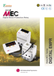
Troubleshooting and Fault Information
Chapter
6
Fault Information
Figure 6.1 - Fault Display
P07 - [Last Fault]
Fault Code Number➀
Fault LED - (Without Program Keypad
Module)
Controllers without a program keypad module
come equipped with a fault LED. When the fault
LED illuminates, a fault condition exists.
0 7
2 2
➀ See Table 6.A below for fault descriptions.
Controllers equipped with a program keypad
module will flash the display when a fault is
present. If a fault occurs, parameter 07 – [Last
Fault] displays. You can cross reference the
number that appears on the display (e.g., 22) with
the fault numbers listed in Table 6.A.
Tips To Clear a Fault
IMPORTANT:If a fault occurs, it is important to
address and correct the fault as well as the
condition that caused the fault.
To clear a fault, perform one of the following:
D Press the program keypad’s stop button.
D Cycle power to the controller.
D Cycle the TB3 stop input signal to the
controller .
D Set P54 – [Clear Fault] parameter to a “1”.
Table 6.A Bulletin 160 Fault Descriptions
ÁÁÁ
ÁÁÁÁ
ÁÁÁÁÁÁÁÁÁÁÁÁ
ÁÁÁÁÁÁÁÁÁÁÁÁÁ
ÁÁÁ
ÁÁÁÁ
ÁÁÁÁÁÁÁÁÁÁÁÁ
ÁÁÁÁÁÁÁÁÁÁÁÁÁ
ÁÁÁ
ÁÁÁÁÁÁÁÁÁÁÁÁ
ÁÁÁÁÁÁÁÁÁÁÁÁÁ
ÁÁÁÁ
ÁÁÁ
ÁÁÁÁ
ÁÁÁÁÁÁÁÁÁÁÁÁ
ÁÁÁÁÁÁÁÁÁÁÁÁÁ
ÁÁÁ
ÁÁÁÁ
ÁÁÁÁÁÁÁÁÁÁÁÁ
ÁÁÁÁÁÁÁÁÁÁÁÁÁ
ÁÁÁ
ÁÁÁÁ
ÁÁÁÁÁÁÁÁÁÁÁÁ
ÁÁÁÁÁÁÁÁÁÁÁÁÁ
ÁÁÁ
ÁÁÁÁ
ÁÁÁÁÁÁÁÁÁÁÁÁ
ÁÁÁÁÁÁÁÁÁÁÁÁÁ
ÁÁÁ
ÁÁÁÁ
ÁÁÁÁÁÁÁÁÁÁÁÁ
ÁÁÁÁÁÁÁÁÁÁÁÁÁ
ÁÁÁÁ
ÁÁÁÁÁÁÁÁÁÁÁÁ
ÁÁÁÁÁÁÁÁÁÁÁÁÁ
ÁÁÁ
ÁÁÁ
ÁÁÁÁ
ÁÁÁÁÁÁÁÁÁÁÁÁ
ÁÁÁÁÁÁÁÁÁÁÁÁÁ
ÁÁÁ
ÁÁÁÁ
ÁÁÁÁÁÁÁÁÁÁÁÁ
ÁÁÁÁÁÁÁÁÁÁÁÁÁ
ÁÁÁ
ÁÁÁÁ
ÁÁÁÁÁÁÁÁÁÁÁÁ
ÁÁÁÁÁÁÁÁÁÁÁÁÁ
ÁÁÁ
ÁÁÁÁ
ÁÁÁÁÁÁÁÁÁÁÁÁ
ÁÁÁÁÁÁÁÁÁÁÁÁÁ
ÁÁÁ
ÁÁÁÁ
ÁÁÁÁÁÁÁÁÁÁÁÁ
ÁÁÁÁÁÁÁÁÁÁÁÁÁ
ÁÁÁ
ÁÁÁÁ
ÁÁÁÁÁÁÁÁÁÁÁÁ
ÁÁÁÁÁÁÁÁÁÁÁÁÁ
ÁÁÁ
ÁÁÁÁ
ÁÁÁÁÁÁÁÁÁÁÁÁ
ÁÁÁÁÁÁÁÁÁÁÁÁÁ
ÁÁÁ
ÁÁÁÁÁÁÁÁÁÁÁÁÁÁÁÁ
ÁÁÁÁÁÁÁÁÁÁÁÁÁ
Fault
Number
Fault
Indication
Fault Description
03
Power Loss
Fault
DC Bus voltage remains below 85% nominal on
power up for longer than 5 seconds.
Monitor incoming AC line for low voltage or line power
interruption.
04
Under Voltage DC Bus voltage fell below the minimum. For
Fault
controllers rated at input voltage 200-240 VAC,
undervoltage trip occurs at 210 VDC bus voltage
(equivalent to 150 VAC incoming line voltage).
For controllers rated at input voltage 380-460
VAC, undervoltage trip occurs at 390 VDC bus
voltage (equivalent to 275 VAC incoming line
voltage).
Monitor incoming AC line for low voltage or line power
interruption.
05
Over Voltage
Fault
Bus overvoltage caused by motor regeneration. Monitor
incoming AC line for excessive voltage. Extend the
decel time or install dynamic brake module or external
capacitor module. See Appendix A.
DC Bus maximum voltage exceeded. For
controllers rated at input voltage 200-240 VAC,
overvoltage trip occurs at 410 VDC bus voltage
(equivalent to 290 VAC incoming line voltage).
For controllers rated at input voltage 380-460
VAC, overvoltage trip occurs at 815 VDC bus
voltage (equivalent to 575 VAC incoming line
voltage ).
Corrective Action
6–1
Chapter 6 - Troubleshooting and Fault Information
Table 6.A Bulletin 160 Fault Descriptions
(continued)
Fault
Number
Fault
Indication
Fault Description
Corrective Action
06
Motor Stall
Fault
Motor has stalled. Motor load is excessive.
07
Motor
Overload
Fault
Internal electronic overload trip. Excessive motor Reduce motor load until controller output current
does not exceed the current set by P42 - [Motor
load exists.
Overload Current]. Reduce P38 - [Boost Volts].
08
Over
Temperature
Fault
Excessive heat detected.
Clear blocked or dirty heat sink fins. Check ambient
temperature. Check for blocked or non-operating fan.
12
Overcurrent
FauIt
Overcurrent detected in hardware trip circuit.
Check short circuit at the controller output or exces
sive load conditions at the motor.
22
Controller
Reset FauIt
Stop input not present.
Check stop connection at TB3, terminal 8.
32
EEPROM
Fault
EEPROM has invalid data.
Reset EEPROM using P56 - [Reset Defaults].
33
Max Retries
Fault
Controller failed to reset fault within the number
of retries set in P50 - [Restart Tries].
Repair system fault.
ÁÁÁÁ
ÁÁÁÁ
ÁÁÁÁÁÁÁÁÁÁÁÁ
ÁÁÁÁÁÁÁÁÁÁÁÁÁ
ÁÁÁÁ
ÁÁÁÁ
ÁÁÁÁÁÁÁÁÁÁÁÁ
ÁÁÁÁÁÁÁÁÁÁÁÁÁ
ÁÁÁÁ
ÁÁÁÁ
ÁÁÁÁÁÁÁÁÁÁÁÁ
ÁÁÁÁÁÁÁÁÁÁÁÁÁ
ÁÁÁÁ
ÁÁÁÁ
ÁÁÁÁÁÁÁÁÁÁÁÁ
ÁÁÁÁÁÁÁÁÁÁÁÁÁ
ÁÁÁÁ
ÁÁÁÁ
ÁÁÁÁÁÁÁÁÁÁÁÁ
ÁÁÁÁÁÁÁÁÁÁÁÁÁ
ÁÁÁÁ
ÁÁÁÁ
ÁÁÁÁÁÁÁÁÁÁÁÁ
ÁÁÁÁÁÁÁÁÁÁÁÁÁ
ÁÁÁÁ
ÁÁÁÁÁÁÁÁÁÁÁÁ
ÁÁÁÁÁÁÁÁÁÁÁÁÁ
ÁÁÁÁ
ÁÁÁÁ
ÁÁÁÁ
ÁÁÁÁÁÁÁÁÁÁÁÁ
ÁÁÁÁÁÁÁÁÁÁÁÁÁ
ÁÁÁÁ
ÁÁÁÁ
ÁÁÁÁÁÁÁÁÁÁÁÁÁÁÁÁÁÁÁÁÁÁÁÁÁ
6–2
Longer acceleration time or a reduced load required.
38
Phase U Fault Phase to ground fault detected between
controller and motor in phase U.
Check the wiring between the controller and motor.
Check motor for grounded phase.
39
Phase V Fault Phase to ground fault detected between
controller and motor in phase V.
Check the wiring between the controller and motor.
Check motor for grounded phase.
40
Phase W
Fault
Phase to ground fault detected between
controller and motor in phase W.
Check the wiring between the controller and motor.
Check motor for grounded phase.
41
UV Short
Fault
Excessive current has been detected between
these two controller output terminals.
Check the motor and external wiring to the controller
output terminals for a shorted condition.
42
UW Short
Fault
Excessive current has been detected between
these two controller output terminals.
Check the motor and external wiring to the controller
output terminals for a shorted condition.
43
VW Short
Fault
Excessive current has been detected between
these two controller output terminals.
Check the motor and external wiring to the controller
output terminals for a shorted condition.
46
Power Test
Fault
Fault detected during initial startup sequence.
Check controller wiring. Check motor wiring.
48
Reprogram
Fault
Occurs when controller parameters are reset to
defaults.
Clear fault.
Chapter 6 - Troubleshooting and Fault Information
Table 6.B Troubleshooting
Problem
Motor does not start
(No output voltage to motor).
Corrective Action
1. Check power circuit.
D
Check supply voltage.
D
Check all fuses and disconnects.
2. Check motor.
D
Verify that motor is connected properly.
3. Check control input signals.
D
Verify that START signal is present.
D
Verify that STOP signal is present.
D
Verify that RUN FORWARD and RUN REVERSE signals are NOT both active.
4. Check P46 - [Input Mode Select].
D
Controller Started but motor
NOT rotating.
(P01 - [Output Frequency]
displays 0.0").
If P46 - [Input Mode Select] is set to 2", only the program keypad module Start button will start
the motor.
1. Check motor.
D
Verify that motor is connected properly.
2. Check frequency source P06 - [Frequency Command].
D
Verify that frequency signal is present at terminal block TB3.
-10 +10V signal
4-20 mA signal
D
Verify that Preset Frequencies are set properly.
3. Check control input signals.
D
Verify that SW1, SW2 and SW3 are correct. (Refer to the chart at the end of Chapter 5).
4. Check parameter settings.
Motor not accelerating properly.
D
Verify that P59 - [Freq Select] is showing desired frequency source.
D
Verify that P58 - [Internal Frequency] is the desired value.
1. Check motor.
D
Verify that motor is connected properly.
D
Verify that no mechanical problems exist.
2. Check parameter settings.
Can not operate in RUN FWD/
RUN REV" mode.
D
Verify that P30 - [Accel Time 1] or P69 - [Accel Time 2] is set properly.
D
Verify that P43 - [Current Limit] is set properly.
D
Verify that P38 - [Boost Volts] is set properly.
1. Verify that P46 - [Input Mode Select] is set to 1".
2. Verify that power has been cycled for above change to take effect.
3. Verify that both RUN FORWARD and RUN REVERSE switches are NOT closed simultaneously.
6–3
Chapter 6 - Troubleshooting and Fault Information
Block Diagram of Bulletin 160 Analog
Signal Follower
Brake Module
BR+
F
r
e
q
u
e
n
c
y
DC+
DC-
L1/R
T1/U
L2/S
T2/V
L3/T
T3/W
R
e
f -10 to +10V
e or
Potentiometer
r
e
n or
c
4 - 20 mA
e
Reverse
Start
Stop
Common
6–4
Capacitor Module
BR-
GND/PE
TB3 - 1
Control
Power
TB3 - 2
Bus
Voltage
Circuitry
TB3 - 3
(Common)
Motor
GND/PE
Current
Circuitry
Fault Feedback
TB3 - 4
Program Keypad
Module
CPU
TB3 - 5
TB3 - 6
TB3 - 8
TB3 - 7
Opto
Isolator
Relay
Circuitry
TB3 - 9
Customer
TB3 - 10 Programmable
Output
TB3 - 11