1
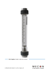
Variable area
flow meter
SKT / SKP / SKPVC
Assembly and operating instructions
Variable area flow meter
SKT / SKP / SKPVC
A. Kirchner & Tochter GmbH Dieselstraße 17 · D-47228 Duisburg
Fon: +49 2065 9609-0 · Fax: +49 2065 9609-22 Internet: www.kt-web.de · e-mail: [email protected]
Version 2.0
Variable area
flow meter
2
SKT / SKP / SKPVC
Contents
1.
General ................................................................................................................................................................ 3
1.1. Exclusion of liability .................................................................................................................................... 3
2.
Safety.................................................................................................................................................................... 3
2.1. Explanation of pictographs and signs .............................................................................................. 3
2.2. Safety information for the owner and the operators ............................................................... 3
2.3. Intended use ................................................................................................................................................ 4
2.4. Safety information for the owner and the operators ............................................................... 5
2.5. Regulations and guidelines ................................................................................................................... 5
2.6. Notice as required by the hazardous materials directive ...................................................... 5
3.
Transport and storage................................................................................................................................. 5
4.
4.1.
4.2.
Installation.......................................................................................................................................................... 6
Preparatory work prior to installation ............................................................................................. 6
Installing ......................................................................................................................................................... 7
5.
Start-up................................................................................................................................................................ 7
6.
Readings in operation................................................................................................................................... 7
7.
7.1.
Limit value contacts....................................................................................................................................... 8
Connection of limit value contacts..................................................................................................... 8
8.1.
Maintenance and cleaning ......................................................................................................................... 9
Dismantling and assembly of the measuring cylinder ............................................................. 9
9.1.
Service ................................................................................................................................................................. 9
Disposal.......................................................................................................................................................... 9
8.
9.
10.
Technical data ...............................................................................................................................................10
10.1.
Limit switches Z 40 und Z 42 for flow meter SKT/SKP/SKPVC.............................12
10.2.
Measuring sensor Z 60 for flow meter SKT/SKP/SKPVC .........................................14
10.3.
Low voltage directive .......................................................................................................................15
A. Kirchner & Tochter GmbH Dieselstraße 17 · D-47228 Duisburg
Fon: +49 2065 9609-0 · Fax: +49 2065 9609-22 Internet: www.kt-web.de · e-mail: [email protected]
Version 2.0
Variable area
flow meter
3
SKT / SKP / SKPVC
1.
General
These assembly and operating instructions apply to variable area flow meter, type SKT,
SKP and SKPVC.
All information contained in these operating instructions on assembly, operation, repairs and maintenance has to be observed and adhered to.
The operating instructions form an integral part of the sprinkler measuring orifice; they
have to be kept at a suitable location in the vicinity of the place of application and must
be accessible for the operators.
In case of interaction of different plant components, the operating instructions of those
also have to be observed.
1.1. Exclusion of liability
Kirchner und Tochter will not accept any liability for damage or disruptions caused by
operating errors, non-observance of this assembly and operating instructions, inexpert
execution of assembly and repair work or by the improper use of the variable
flow meter.
2.
Safety
2.1. Explanation of pictographs and signs
Pictograph on work safety
This pictograph can be found at all hints on work safety in these assembly and operating instructions pointing out hazards for life and limb of persons.
Further, this pictograph highlights safety hints in these operating instructions that
point to regulations, guidelines or operating sequences that must be observed without
fail. Non-observance may result in damage to or a destruction of the variable area flow
meter and/or other parts of the installation.
2.2. Safety information for the owner and the operators
These assembly and operating instructions contain important information to be observed on the assembly, the operation, on repairs and maintenance of the sprinkler
measuring orifice. Each person charged with the assembly, the operation, repairs and
maintenance must have read and understood these operation instructions.
Non-observance of these assembly and operating instructions, or inexpertly conducted
assembly and repair work may result in disruptions of the sprinkler system. As a consequence, man or animal may be at risk or material assets may be damaged.
Hazards by electric energy or released media energy must be prevented.
A. Kirchner & Tochter GmbH Dieselstraße 17 · D-47228 Duisburg
Fon: +49 2065 9609-0 · Fax: +49 2065 9609-22 Internet: www.kt-web.de · e-mail: [email protected]
Version 2.0
Variable area
flow meter
4
SKT / SKP / SKPVC
2.3. Intended use
Series SKT, SKP and SKPVC devices are variable area flow meters for liquids and
gases, and are designed for installation in vertical pipe runs. Installation in the pipeline
may only be carried out in accordance with these Instructions.
Select the version of the variable area flow meter on the basis of the pipe diameter at
the installation location of the device. The limit values for the device are specified in
Chapter 10 and must be complied with.
Any modifications or other changes made to the device may be carried out solely by
Kirchner und Tochter. Installation in horizontal pipe runs is possible by using appropriately constructed pipe bends.
The direction of flow must always be from bottom to top. Details pertaining to the fluid
product and the operating conditions are noted on the measuring glass.
A. Kirchner & Tochter GmbH Dieselstraße 17 · D-47228 Duisburg
Fon: +49 2065 9609-0 · Fax: +49 2065 9609-22 Internet: www.kt-web.de · e-mail: [email protected]
Version 2.0
Variable area
flow meter
5
SKT / SKP / SKPVC
2.4. Safety information for the owner and the operators
The personnel charged with the assembly, the operation, repairs and maintenance
must be qualified to fulfill the respective tasks and must have been trained and instructed with regards to the task in question.
2.5. Regulations and guidelines
Apart from the information contained in these assembly and operating instructions,
the regulations, guidelines and standards such as DIN EN, as well as the DVGW and
VdS guidelines in case of branch-oriented applications must be observed; the same is
true for the regulations on the prevention of accidents valid in the destination country.
2.6. Notice as required by the hazardous materials directive
In accordance with the law concerning handling of waste (critical waste) and the hazardous materials directive (general duty to protect), we would point out that all flow
monitors returned to Kirchner und Tochter for repair are required to be free from any
and all hazardous substances (alkaline solutions, acids, solvents, etc.).
Make sure that devices are thoroughly rinsed out to neutralize hazardous
substances.
3.
Transport and storage
Always use the original packing for transport, handling and storage. Protect the device
against rough handling, impact, jolts, etc.
A. Kirchner & Tochter GmbH Dieselstraße 17 · D-47228 Duisburg
Fon: +49 2065 9609-0 · Fax: +49 2065 9609-22 Internet: www.kt-web.de · e-mail: [email protected]
Version 2.0
Variable area
flow meter
6
SKT / SKP / SKPVC
4.
Installation
4.1. Preparatory work prior to installation
Preparing the installation location:
1.
Check the pipe run at the installation location. VA flow meters are only suitable for
vertical installation with the direction of flow being from bottom to top. For all
other installation situations appropriate pipe bends need to be fitted in the existing
pipeline to ensure vertical flow through the device from below. The region of
steady flow should be 4 - 6x DN upstream and downstream of the installation location. Particularly in the case of gaseous media, locate control equipment downstream of the measuring device.
2.
If necessary, support the ends of the pipeline to prevent vibration from being
transmitted to the flow meter.
3.
Clean by blowing out or flushing the pipes leading to the device before connecting
up.
4.
Prepare the installation point before starting to fit the flow meter. Make sure sealing faces are correctly spaced apart and in true alignment.
5.
On no account the VA flow meter should be used to pull the ends of the pipeline
together (stress-free installation!). Do not tighten union nuts excessively.
Preparation of the flow meter:
1.
Take the device out of the transport packaging.
2.
Open the variable flow meter and remove the the transportation safety net.
3.
Check that the float can move freely in the flow meter.
4.
Have ready sealings and sealing material (such as hemp). They do not belong to
the scope of delivery.
A. Kirchner & Tochter GmbH Dieselstraße 17 · D-47228 Duisburg
Fon: +49 2065 9609-0 · Fax: +49 2065 9609-22 Internet: www.kt-web.de · e-mail: [email protected]
Version 2.0
Variable area
flow meter
7
SKT / SKP / SKPVC
4.2. Installing
1. Remove the insert and the union nuts from the device.
2. Slide the union nuts over the pipe ends at the installation location.
3. Fit the inserts on to the pipe ends.
4. Slide the device at both ends in the installation location.
5. Screw the union nuts to the measuring cylinder and tighten down so that the device is mounted without stresses in the pipeline.
5.
Start-up
The flow meter must have been properly installed before it is started up.
1. Test all device connections.
2. To set the flow: pressurize the pipelines by slowly opening the shut-off valves.
On liquid service: carefully evacuate the pipeline.
3. Check that all components are leak-tight and, if necessary, tighten down threaded
joints and screw connections.
6.
Readings in operation
The flow value is read off from the scale on the glass cone at the top edge of the float.
The measured-value readings are only correct when the operating condition at the
measuring point (flowing medium, operating pressure and temperature) corresponds
to the values marked on the measuring cylinder. If operating conditions should differ,
the measured value must be corrected with the aid of the general float equation, which
you will find in our technical documents.
You can also do the recalculation with the help of our conversion program given on our
home page: www.kt-web.de, Section “Physical Basics“.
A. Kirchner & Tochter GmbH Dieselstraße 17 · D-47228 Duisburg
Fon: +49 2065 9609-0 · Fax: +49 2065 9609-22 Internet: www.kt-web.de · e-mail: [email protected]
Version 2.0
Variable area
flow meter
8
SKT / SKP / SKPVC
7.
Limit value contacts
The flow meter can be equipped with limit value contacts to provide local indication
with monitoring function.
The limit value contacts consist of a limit contact (reed switch) that is switched over by
the magnet integrated in the float. The limit contact is guided at the measuring cylinder
and can be adjusted over the full measuring range. The reed contacts have a bistable
characteristic.
Uncontrolled current and voltage peaks can occur in the case of inductive or capacitive
loads, e.g. from contactors or solenoid valves. Such peaks will also occur, depending on
cable geometry, where cables exceed a certain length.
We therefore recommend using an MSR contact protection relay, which is additionally
available. This will increase the contact rating and prevent occurrence of inductive and
capacitive peaks, thus ensuring long service life of the contacts.
Electrical data and limit values are specified in Section 10.1.
7.1. Connection of limit value contacts
Electrical connection of the device must be carried out in conformity with the
relevant VDE regulations (or equivalent national standards) and in accordance
with the regulations issued by the local power supply utility.
1.
Disconnect the plant from supply before connecting the limit contact.
2.
Provide a protective circuit for the contacts in keeping with their capacity.
3.
Connect line-side fuse elements matched to consumption.
4.
Connect the cable using the supplied right-angle plug. Assigned are terminals 1
and 2. Earth and terminal 3 are not assigned. The circuit diagram for limit contacts is shown in the Technical Data, Section 10.
A. Kirchner & Tochter GmbH Dieselstraße 17 · D-47228 Duisburg
Fon: +49 2065 9609-0 · Fax: +49 2065 9609-22 Internet: www.kt-web.de · e-mail: [email protected]
Version 2.0
Variable area
flow meter
9
SKT / SKP / SKPVC
8.
Maintenance and cleaning
The flow meter is maintenance-free. Should the glass cone become fouled, the meter
can be removed from the pipeline as follows.
8.1. Dismantling and assembly of the measuring cylinder
1. Depressurize the pipeline
2. Dismantle the device by first removing the union nuts.
3. Remove the measuring cylinder from the installation location.
Assemble in reverse sequence.
9.
Service
All devices with defects or deficiencies should be sent direct to our repair department.
To enable our customer service facility to deal with complaints and repairs as quickly
as possible, you are kindly requested to coordinate the return of devices with our sales
department, Tel. +49 2065 9 60 90.
9.1. Disposal
For a better environment:
Please help us protect our environment by disposing of the parts used in accordance
with the relevant legislation or by recycling same.
A. Kirchner & Tochter GmbH Dieselstraße 17 · D-47228 Duisburg
Fon: +49 2065 9609-0 · Fax: +49 2065 9609-22 Internet: www.kt-web.de · e-mail: [email protected]
Version 2.0
Variable area
flow meter
10
SKT / SKP / SKPVC
10. Technical data
Nominal pressure rating
PN 10 at 20 °C
Operating temperatur
Trogamid: 0 to 60 °C
Polysulfon: 0 to100 °C
Polyvinyl chloride: 0 to 40 °C
Measuring range
1:10
Accuracy class
4 acc. to VDI/VDE 3513, sheet 2
Special scales
See special table
Connection
gluing sleeve acc. to DIN 8063,
optionally thread acc. to DIN 228 T 1
Screw connection with
internal thread acc. ISO 7-1
Materialis
Measuring cylinder
SKT
Trogamid
SKP Polysulfon
SKP k Polysulfon
SKPVC Polyvinyl cloride
Floats
PVDF red or 1.4571
Float receptacles
PVDF
Fittings and inserts
PVC, optionally PP, PVDF, malleable cast iron
Zn, 1.4571
Seals
EPDM, optionally Viton
A. Kirchner & Tochter GmbH Dieselstraße 17 · D-47228 Duisburg
Fon: +49 2065 9609-0 · Fax: +49 2065 9609-22 Internet: www.kt-web.de · e-mail: [email protected]
Version 2.0
Variable area
flow meter
11
SKT / SKP / SKPVC
Ød
Dimensions SKT/SKP/SKPVC
DN
25
40
50
65
G
1 1/2
2 1/4
2 3/4
3 1/2
L
L1
335
335
335
335
341
341
341
341
L2
385
403
417
429
Ød
32
50
63
75
DN
ØD
60
83
103
122
G
L
3/4
165
185
200
1
1 1/2
1
L1
L2
199
191 223
206 250
185 191 223
171
Ød
ØD
16
20
32
20
35
43
60
43
50
1000
40
30
500
20
10
200
ØD
A. Kirchner & Tochter GmbH Dieselstraße 17 · D-47228 Duisburg
Fon: +49 2065 9609-0 · Fax: +49 2065 9609-22 Internet: www.kt-web.de · e-mail: [email protected]
Version 2.0
L1
G
L
DN
25
40
50
65
L2
Dimensions SKP-k
Variable area
flow meter
12
SKT / SKP / SKPVC
10.1. Limit switches Z 40 und Z 42 for flow meter SKT/SKP/SKPVC
Application
Limit switches Z 40 and Z42 are designed for
the external monitoring of limited flow values on
SKT/SKP and SKPVC flow meters.
They are slipped on to the guide on the flow meter
and can be set to any desired value on the
appropriate scale
Function
A magnet built into the float closes or opens
a potted reed contact in the limit switch.
The switching function is bistable, which means
that the switching status is maintained even when
the magnetic float is located a distance away from
the contact.
Switching status:
Limit switch Z 40 min
Limit switch Z42 max
Float
above switch
open
closed
Float
below switch
closed
open
Note:
When retrofitting limit value contacts, be sure to replace the standard float by a magnetic
float. The magnetic float is clearly marked with an "M" on the top side.
10.2. Directions for assembly
Slide contact on the dovetail of the flow meter.
Set the desired value and tighten clamping screw.
Remove plug connector and wire up.
Screw on plug connector with seal inserted.
A. Kirchner & Tochter GmbH Dieselstraße 17 · D-47228 Duisburg
Fon: +49 2065 9609-0 · Fax: +49 2065 9609-22 Internet: www.kt-web.de · e-mail: [email protected]
Version 2.0
Variable area
flow meter
13
SKT / SKP / SKPVC
10.3. Technical data Z40 / Z42:
Voltage switched
Contact rating
Current switched
Volume resistance
Insulation resistance
Allowable ambient temperature
Type of protection
Make/break hysteresis Z 31
max. 230V~
max. 10 W / 12 VA
max. 0.5 A
< 200 mΩ
> 1011 Ω
0 - + 55 °C
Acc. DIN 40050 – IP 65
1 – 2 mm float travel
Note!!
The values for electric strength, contact rating and current switched should not be exceeded on any account, not even for short times, as this could otherwise result in damage to
the reed contact.
Terminal assignment Z40 / Z 42
The contacts feature two terminals 1 + 2 and one earthing terminal.
Voltage is supplied via 1 + 2. Assignment is freely selectable.
A. Kirchner & Tochter GmbH Dieselstraße 17 · D-47228 Duisburg
Fon: +49 2065 9609-0 · Fax: +49 2065 9609-22 Internet: www.kt-web.de · e-mail: [email protected]
Version 2.0
Variable area
flow meter
14
SKT / SKP / SKPVC
10.4. Measuring sensor Z 60 for flow meter SKT/SKP/SKPVC
Function elements
A – Flow meter SKT/SKP/SKPVC with
monostable magnetic float
B – Measuring sensor Z 60
C – Plug connector
D – Dovetail guide
E – Clamping screws for fastening and
adjusting the sensor
Special features
Easy to assemble
Analog output signal 4 – 20 mA
24 V DC voltage supply+/- 10%
Degree of Protection IP 65
Casing made of PVC-U
DIN plug connection
Function
The Z60 measuring sensor fitted to the SKT/SKP/SKPVC flow meter is a further
development of the Z50 sensor. In contrast to the previous model, the Z60 has
no reed contacts; instead, it features a special, newly developed electronic device with microprocessor and sensors.
The measuring sensor supplies an analog output signal of 4 – 20 mA that is
proportional to the position of the magnetic float. This signal can be further
processed in order to control processes, for example by way of a PLC, or to
provide exact indications of the flow rate via an external display.
The sensor can also be retrofitted, providing the flowmeter is fitted with a
monostable magnetic float (axially magnetized mounting position: south top,
north bottom). To obtain best possible reproducibility, programming is always
factory-set and adapted to the respective measuring range since the various
scales all have a different resolution. Therefore, when ordering, please state
the required measuring range.
A. Kirchner & Tochter GmbH Dieselstraße 17 · D-47228 Duisburg
Fon: +49 2065 9609-0 · Fax: +49 2065 9609-22 Internet: www.kt-web.de · e-mail: [email protected]
Version 2.0
Variable area
flow meter
15
SKT / SKP / SKPVC
Directions for assembly
1. Slide sensor on to the dovetail guide of the flow meter.
2. Adjust marking on sensor to the 50% scale mark on
the flow meter.
3. Tighten clamping screws.
4. Remove plug, and wire as specified.
Electrical Connection
Pin 1 : Operating voltage 24 V
1Ø
+ 24 V
Pin 2 : Output signal 4-20 mA
2Ø
4–
Pin 3 : 0 V
3Ø
20 mA------R
Technical data
Operating voltage
Current consumption
Load impedance
Current output
Measuring accuracy
24 V ± 10 %
< 50 mA
min. 0 Ohm, max. 500 Ohm
4-20 mA (3-wire-technique)
< 1%
Degree of protection
Ambient temperature
Connection
IP 65 to DIN 40050
0°C – + 50°C
DIN plug connector DIN 43650
10.5. Low voltage directive
Above 50 V AC/75 V DC, contacts are subject to the EC Low-Voltage Directive. The
user is required to verify their use accordingly.
A. Kirchner & Tochter GmbH Dieselstraße 17 · D-47228 Duisburg
Fon: +49 2065 9609-0 · Fax: +49 2065 9609-22 Internet: www.kt-web.de · e-mail: [email protected]
Version 2.0
Variable area
flow meter
16
SKT / SKP / SKPVC
The equipment from Kirchner und Tochter has
been tested in compliance with applicable
CE-regulations of the European Community.
The respective declaration of conformity is
available on request.
Technical data supplied without liability.
The current valid version of our documents can be
found under this URL: www.kt- web.de
The Kirchner und Tochter QM-System is certified
in accordance with DIN-EN-ISO 9001:2008.
The quality is systematically adapted to the
continuously increasing demands.
A. Kirchner & Tochter GmbH Dieselstraße 17 · D-47228 Duisburg
Fon: +49 2065 9609-0 · Fax: +49 2065 9609-22 Internet: www.kt-web.de · e-mail: [email protected]
Version 2.0