1
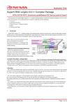
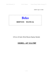
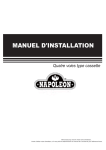
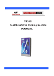
ENGLISH
E-II-YDCL-P-0907
INSTALLATION MANUAL
PANEL FOUR WAY CASSETTE
For correct installation, read this manual before starting installation.
Only trained and qualified service personnel should install, repair or service air conditioning equipment. Users
should not install the air conditioner by themselves.
All pictures are only sketches. If there is any difference between pictures in this manual and the actual shape
of the air conditioner you purchased, the actual shape shall prevail.
1. Install The Panel
CAUTIONS
Never put the panel face down on floor or against the wall, or on bulgy objects.
Never crash or strike it.
(1) Remove the inlet grid.
a. Slide two grid switches toward the middle at the same time, and then pull them up. (Refer to chart 8)
0
b. Draw the grid up to an angle of about 45 , and remove it. (Refer to chart 9)
(2) Remove the installation covers at the four corners.
Wrench off the bolts, loose the rope of the installation covers, and remove them. (Refer to chart 10)
45
Grid switch
Chart 8
Chart 9
Chart 10
(3) Install the panel
a. Align the swing motor on the panel to the tubing joints of the body properly. ( Refer to chart 11)
b. Fix hooks of the panel at swing motor and its opposite sides to the hooks of corresponding water
receiver. ( Refer to chart 11 ) Then hang the other two panel hooks onto corresponding hangers of
the body. ( Refer to chart 11 )
CAUTIONS Do not coil the wiring of the swing motor into the seal sponge.
c. Adjust the four panel hook screws to keep the panel horizontal, and screw them up to the ceiling
evenly. ( Refer to chart 11 )
d. Regulate the panel in the direction of the arrow in Chart11 slightly to fit the panel's center to the
center of the ceiling's opening. Guarantee that hooks of four corners are fixed well.
e. Keep fastening the screws under the panel hooks, until the thickness of the sponge between the
body and the panel's outlet has been reduced to about 4~6mm. The edge of the panel should
contact with the ceiling well. (Refer to chart 12)
Malfunction described in Chart13 can be caused by inappropriate tightness the screw.
If the gap between the panel and ceiling still exists after fastening the screws, the height of the
indoor unit should be modified again. ( Refer to chart 14-left)
You can modify the height of the indoor unit through the openings on the panel's four corners, if the
lift of the indoor unit and the drainpipe is not influenced (refer to chart 14-right).
(4) Hang the air-in grid to the panel, then connect the lead terminator of the swing motor and that of
the control box with corresponding terminators on the body respectively.
(5) Relocate the air-in grid in the procedure of reversed order.
(6) Relocate the installation cover.
a. Fasten the rope of installation cover on the bolt of the installation cover. (Refer to chart 15-left)
b. Press the installation cover into the panel slightly. (Refer to chart 15-right)
Tubing joint Hook panel
Outlet joint
Water- receiver
Leakage
Ceiling
Pollution
Swing Motor
Water condensation
Chart 13
Loosen upper nut
Hook-bolt
Cross-screwdriver
Chart 11
Gap not allowed
Chart 14
body
4-6mm
outlet foam
Ceiling
panel sponge
panel
panel foam1
Adjust lower nut
Installation cover,s rope
Tap Screw
Fan
panel foam 2
Chart 15
air out
Chart 12
Slide the four sliders
in the corresponding
channel when installing
the cover
DE - COMMISSIONING DISMANTLING & DISPOSAL
This product contains refrigerant under pressure, rotating parts, and electrical connections which
may be a danger and cause injury!
All work must only be carried out by competent persons using suitable protective clothing and safety precautions.
Read the Manual
Risk of electric shock
Unit is remotely controlled
and may start without warning
1. Isolate all sources of electrical supply to the unit including any control system supplies switched by the unit. Ensure that all points of electrical and gas
isolation are secured in the OFF position. The supply cables and gas pipework may then be disconnected and removed. For points of connection refer
to unit installation instructions.
2. Remove all refrigerant from each system of the unit into a suitable container using a refrigerant reclaim or recovery unit. This refrigerant may then be
re-used, if appropriate, or returned to the manufacturer for disposal.Under No circumstances should refrigerant be vented to atmosphere. Where
appropriate, drain the refrigerant oil from each system into a suitable container and dispose of according to local laws and regulations governing
disposal of oily wastes.
3. Packaged unit can generally be removed in one piece after disconnection as above. Any fixing down bolts should be removed and then unit lifted from
position using the points provided and equipment of adequate lifting capacity. Reference MUST be made to the unit installation instructions for unit
weight and correct methods of lifting. Note that any residual or spilt refrigerant oil should be mopped up and disposed of as described above.
4. After removal from position the unit parts may be disposed of according to local laws and regulations.
E-II-YDCL-P-0907
ENGLISH