Transcript
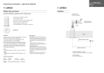
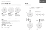
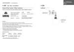
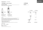
ingenium www.ingeniumsl.com fire and gas sensors · DTV · DTV [ DTV · DTV-BUS · DTV-W ] Thermovelocimetric Fire Detector Installation To detect fires indicated by sharp temperature changes. Connection to KCtr E5: Gas/Fire Sensors Max. distance: 30m · DTV + Ð Contact detector to be connected to the KCtr smartbox See KCtr diagram Installation of Gas or Fire Sensors LOOP Type • For KCtr connection • Mounted on the ceiling (surface) • Size: 60x85x58mm · DTV-BUS · DTV-W Detector to be connected to wired BUSing®. Detector to be connected to wireless BUSing®. • BUSing® connection • BUSing® wireless connection • Mounted on the ceiling (surface) • Mounted on the ceiling (surface) • Size: Ø 74x26mm • Size: Ø 74x26mm á DTV These types of detectors are mounted on ceilings and detect fires by measuring the rise in temperature produced in the room where they are installed. 3 4 1 +12V A B Ref. + á DTV-BUS 3 4 2 4 2 1 4 2 1 1 Requires 2/3 AA battery supply. Cable 4x0.5mm See B-DTV diagram > Page 111 Detailed connection between sensor and communication bus. • The thermovelocimetric detectors are designed to be placed in areas where smoke might exist or occur, such as kitchens, garages etc. Configuration using Development System (SIDE) • 2 programmable scenes for activation and deactivation of the sensor. • Up to 60 programmable BUS events for each scene. 3 3 Ð 2 Consumes Description Connection of additional DTV sensors Up to 3 sensors can be connected directly to the KCtr input. DTV-W maintenance Must check and/or replace the batteries at least once every two years. á DTV-W Technical Characteristics Device Reference Voltage Supply Current Consumption DTV DTV-BUS DTV-W 9–16V DC (KCtr) Negligible 9–16V DC (BUS) 40mA (BUS) Battery 2/3 AA (3V) – Max. Recommended Distance 30m* – 15m** * maximum recommended distance between sensor and KCtr ** maximum recommended distance to closest radio device (repeater) inalmbrico wireless