1
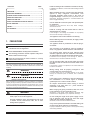
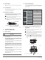
7.4 Wiring connection diagram
8.
Outdoor power
supply
RCCB
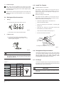
8.1 Capacity set and system address set
Grounding line
Wire slot
Grounding line
CONTROL
Indoor unit
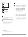
Set the PCB board toggle of the indoor unit electric control box
by the different use. After setting, make sure to switch off the
power, and then switch on it. If you don’t switch on the power,
the capacity you set can not implement.
Indoor power
DE
BC
Fig.7-3
3 4 56
Signal wire for communicate
indoor unit and outdoor unit
F 012
9
78 A
RCCB
POWER_S
Fig.8-1
FUNCTION DESCRIPTION:
POWER_S: Cooling capacity set, use for setting the cooling
capacity of the machine.
Table.8-1
7.5 Signal wire of indoor/outdoor unit
POWER_S
The control line should be shielded wire. Using other wiring
shall create signal interference, thus leading to error
operation.
Single end to shield net of shielded wire should be grounded.
Note: The shield net should be grounded at the wiring
terminal of outdoor unit. The inlet and outlet wire net of indoor
communication wire should be connected directly and could
not be grounded, and form open circuit at the shield net of
final indoor unit.
Control wire could not be bound together with refrigerant
pipeline and power wire. When power wire and control wire is
distributed in parallel form, keep gap between them above
300mm so as to preventing signal interference.
Note: The horsepower
has been set before
leaving the factory ,
anyone can’t
modify it except the
maintenance person.
Toggle switch
For set horsepower
Code
Capacity(Horsepower)
0
1800W(0.6HP)
2200W(0.8HP)
1
2800W(1.0HP)
2
3600W(1.3HP)
3
4500W(1.6HP)
4
5600W(2.0HP)
5
7100W(2.5HP)
6
8000W(3.0HP)
7
9000W(3.2HP)
8
11200W(4.0HP)
9
14000W(5.0HP)
Control wire could not form closed loop.
Control wire has polarity, so be careful when connecting.
Please use 3-core shield wire (more than or equal to 0.75
mm2) for signal wire of indoor/outdoor units, which has
polarity, need to connect correctly.
7.6 Wiring connection
Seal the wiring connection with the insulation material, or the
condensing dew will be caused.
7.7 Terminal board diagram
Please refer to the indoor unit wiring diagram for the wiring.
installation manual
10
CAUTION
The system together have 64 units(0-63), everyone has only
system address code, If two addresses are the same in one
system, the abnormal operation will occur.
If the outdoor unit connected to is not the type of D3、D4、V3、
V4, the last 32 address toggle invalid.
8.2 Network address set
1) Network address is set by communication of indoor and
outdoor unit; the address is the same as indoor address, there
is no need to set separately.
2) The central control of indoor units can be done on outdoor
unit, there is no need to control indoor unit separately, for
details please refer to V4+ outdoor unit manual.
3) For previous control of indoor units, the network can be set
by connecting (X,Y,E) terminals, there is no need to set
network address. The network can also be set by outer
network module and main board (CN20).