1
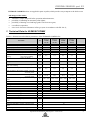
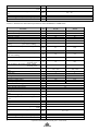
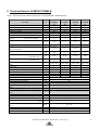
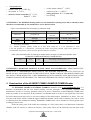
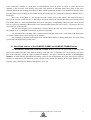
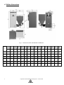
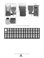
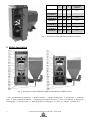
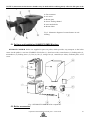
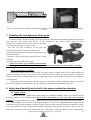
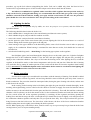
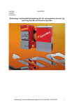
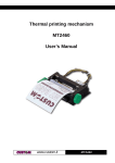
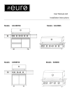
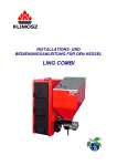
1o
Operation and installation manual 2013.03.06
ORIGINAL MANUAL part 2/2
KLIMOSZ COMBI B boilers are supplied in parts on pallet, which provides easy transport to the boiler room.
Advantages of the boiler:
• Automatic, simple and quick boiler operation and maintenance;
• possibility of installing an automatic pellet lighter;
• possibility of burning wood and large grade coal in an extra grate;
• cost-effective operation;
•
a low level of noxious substances in flue gas (tests in accordance with EN 303-5);
1. Technical Data for KLIMOSZ COMBI
Table 1a. Dimensions and technical parameters of the KLIMOSZ COMBI boiler.
Parametr
kW
kW
%
%
kW
kW
Klimosz
Combi
NG 15
15
15
80
80
5,0 ÷ 15,0
5,0 ÷ 15,0
Klimosz
Combi
NG 20
20
20
80
78
6,0 ÷ 20,0
6,0 ÷ 20,0
Klimosz
Combi
NG 25
25
20
80
78
7,5 ÷ 25,0
6,0 ÷ 20,0
Klimosz
Combi
NG 32
32
20
81,5
82,5
9,6 ÷ 32,0
6,0 ÷ 20,0
kg/h
2,5
3,3
4,1
5,1
kg/h
3,8
5,1
5,1
4,8
dm3
230
230
230
230
days
8,5
6,0
5,0
4,0
days
4,5
3,5
3,5
3,5
g/s
14,50
15,31
17,68
20,06
g/s
14,70
16,7
16,7
13,83
°C
100 ÷ 250
100 ÷ 250
100 ÷ 250
100 ÷ 260
kg
m2
dm3
mm
Pa
bar
bar
bar
-
3
470
35
156
10 ÷ 15
3
490
36
156
10 ÷ 20
SI
Nominal power - pea coal
- pellets
Efficiency - pea coal
Efficiency - pellets
Power regulation scope - pea coal
- pellets
Use of fuel at nominal power – continuous
heating
- pea coal 27,5 MJ/kg
- pellets 18 MJ/kg
Storage bin volume
Approximate combustion time at nominal power
- pea coal 27MJ/kg
- pellets 16MJ/kg
Flow of fumes in the smoke conduit - pea coal
- nominal power
Flow of fumes in the smoke conduit - pellets
- nominal power
Recommended working temperature for heating
water
Boiler class
Mass
Heating area of the boiler
Water volume
Diameter of fumes outlet
Chimney draught
Water maximal working pressure
Water minimal working pressure
Water maximal trial pressure
Fluid group
Recommended working temperature for heating
water
Maximal working temperature for heating water
Minimal temperature of water returning to the
boiler
Maximal permitted level of heating material
Safety valve
°C
3
510
40
156
10 ÷ 20
4,0
5,9
2 – wather
65 ÷ 80
°C
°C
m
bar
Operation and installation manual part 2. 2015.06.09
3
530
50
156
10 ÷ 20
90
50
30
4,0
2
Noise level
Connections of the boiler - heating and returning
water
Resistance of water flow through the boiler ∆t =
20oC
Electric energy consumption (fan / motor)
Electric energy consumption (shot light-option)
Electric insulation
dB
< 65 (A)
2 ” or 6/4” GZ
mbar
0,4 ÷ 20
W
-
230V / 50 Hz
180 / 80
IP 40
Table 1b. Dimensions and technical parameters of the KLIMOSZ COMBI boiler.
Parametr
Nominal power - pea coal
- pellets
Efficiency - pea coal
Efficiency - pellets
Power regulation scope - pea coal
- pellets
Use of fuel at nominal power – continuous
heating
- pea coal 27,5 MJ/kg
- pellets 18 MJ/kg
Storage bin volume
Approximate combustion time at nominal power
- pea coal 27MJ/kg
- pellets 16MJ/kg
Flow of fumes in the smoke conduit - pea coal
- nominal power
Flow of fumes in the smoke conduit - pellets
- nominal power
Recommended working temperature for heating
water
Boiler class
Mass
Heating area of the boiler
Water volume
Diameter of fumes outlet
Chimney draught
Water maximal working pressure
Water minimal working pressure
Water maximal trial pressure
Fluid group
Recommended working temperature for heating
water
Maximal working temperature for heating water
Minimal temperature of water returning to the
boiler
Maximal permitted level of heating material
Safety valve
Noise level
Connections of the boiler - heating and returning
water
Resistance of water flow through the boiler ∆t =
20oC
Electric energy consumption (fan / motor)
Electric energy consumption (shot light-option)
Electric insulation
3
kW
kW
%
%
kW
kW
Klimosz Combi
NG 42
42
36,3
80
80
12,6 ÷ 42
10,9 ÷ 36,3
Klimosz Combi
NG 49
49
43,3
80
80
14,7 ÷ 49
13 ÷ 43,3
kg/h
6,9
8,0
kg/h
9,1
10,8
dm3
230
230
days
3,0
2,5
days
2,0
1,6
g/s
24
30,3
g/s
25
28
°C
120 ÷ 260
120 ÷ 260
kg
m2
dm3
mm
Pa
bar
bar
bar
-
3
613
60
156
15 ÷ 20
3
630
65
156
15 ÷ 20
SI
°C
°C
°C
2,0
3,0
2 – wather
65 ÷ 80
90
50
m
bar
dB
30
4,0
< 65 (A)
2 ” or 6/4” GZ
mbar
0,4 ÷ 20
W
-
230V / 50 Hz
250 / 80
IP 40
Operation and installation manual part 2. 2015.06.09
2. Technical Data for KLIMOSZ COMBI B
Table 2. Dimensions and technical parameters of the KLIMOSZ COMBI B boiler.
Parametr
kW
kW
%
%
kW
kW
Klimosz
Combi B
15
15
15
81
80
5,0 ÷ 15,0
5,0 ÷ 16,0
Klimosz
Combi B
20
20
20
80
78
6,0 ÷ 20,0
6,0 ÷ 20,0
Klimosz
Combi B
32
32
20
81,5
82,5
9,6 ÷ 32
6,0 ÷ 20,0
Klimosz
Combi B
35
35
25
81
81
10,5 ÷ 35
7,5 ÷ 25
kg/h
2,5
3,3
5,1
5,7
kg/h
3,8
5,1
4,8
6,4
dm3
230
230
230
230
dni
8,0
6,5
4,0
3,5
dni
4,5
3,5
3,5
3
g/s
11,2
15,31
17,68
18,9
g/s
12,4
16,7
16,7
18,1
°C
100 ÷ 250
100 ÷ 260
100 ÷ 260
100 ÷ 260
kg
m2
dm3
mm
Pa
bar
bar
bar
-
3
460
31
156
10 ÷ 15
3
475
40
156
10 ÷ 20
3
490
50
156
10 ÷ 20
525
60
156
15 ÷ 20
SI
Nominal power - pea coal
- pellets
Efficiency - pea coal
Efficiency - pellets
Power regulation scope - pea coal
- pellets
Use of fuel at nominal power – continuous
heating
- pea coal 27,5 MJ/kg
- pellets 18 MJ/kg
Storage bin volume
Approximate combustion time at nominal power
- pea coal 27MJ/kg
- pellets 16MJ/kg
Flow of fumes in the smoke conduit - pea coal
- nominal power
Flow of fumes in the smoke conduit - pellets
- nominal power
Recommended working temperature for heating
water
Boiler class
Mass
Heating area of the boiler
Water volume
Diameter of fumes outlet
Chimney draught
Water maximal working pressure
Water minimal working pressure
Water maximal trial pressure
Fluid group
Recommended working temperature for heating
water
Maximal working temperature for heating water
Minimal temperature of water returning to the
boiler
Maximal permitted level of heating material
Safety valve
Noise level
Connections of the boiler - heating and returning
water
Resistance of water flow through the boiler ∆t =
20oC
Electric energy consumption (fan / motor)
Electric energy consumption (shot light-option)
Electric insulation
°C
4,0
8,0
2 – woda
65 ÷ 80
°C
90
50
°C
m
bar
dB
30
4,0
< 65 (A)
2 ” lub 6/4” GZ
mbar
0,4 ÷ 20
W
-
230V / 50 Hz
180 / 80
IP 40
Operation and installation manual part 2. 2015.06.09
4
•
Fuel parameters:
•
calorific value Qir > 15MJ / kg ;
•
•
ash content A r < 12% ;
moisture content coal pellets W r < 15% ,
wood W r < 20% ;
•
•
•
•
volatile matter content V r > 28% ;
ash fusion point t A > 1200 o C ;
caking properties RI < 20 (max 30);
low swelling
ATTENTION!!! The KLIMOSZ heating boilers are not intended for burning waste and no substances other
than those recommended by the manufacturer can be burnt in them.
Table 3. Recommended fuel for burning in automatic mode.
Main fuel
Fuel type
Hard coal
pea grade coal
Substitute
fuel
Biomass
Granulation [mm]
Gr II 8 ÷ 20
(max 30)
Calorific value [MJ/kg]
Fuel type
Granulation [mm]
Calorific value [MJ/kg]
pellets **
Φ6÷8
16 ÷ 18
24 ÷ 28 *
*)
Non-caking, non-coking
**)
Sawdust granulate (pellets) should be at least hard enough for it to be impossible to crush
a few fuel granules in a clenched fist, preventing the feeder from getting jammed. Light colour grades are
recommended, without bark, which can cause deposit formation in the burner.
Table 4. Recommended fuel for burning in manual mode (emergency combustion chamber of the
KLIMOSZ COMBI and KLIMOSZ COMBI B boiler).
Fuel
Unit
Size
non-coking, non-caking hard coal
Wood
(mm)
200
O I [40 ÷ 80]; Ko II [63 ÷ 125]
ATTENTION!!! MOISTURE CONTENT IN FUEL MUST NOT EXCEED 15%. USING MOIST FUEL
RESULTS IN A CONSIDERABLE REDUCTION IN THE BOILER'S POWER CAPACITY (EVEN BY AS
MUCH AS 50%) AND REDUCTION IN THE LIFE-SPAN OF THOSE PARTS OF THE BOILER WHICH ARE
IN CONTACT WITH MOIST FUEL. USING IMPROPER QUALITY OR MOIST FUEL RESULTS IN LOSING
WARRANTY RIGHTS WITH RESPECT TO THE PARTS EXPOSED TO CONTACT WITH SUCH FUEL.
3. Construction of the KLIMOSZ COMBI, KLIMOSZ COMBI B boiler
The KLIMOSZ COMBI and KLIMOSZ COMBI B automatic boiler is not maintenance-free; it is
therefore recommended that the user should carefully read the principles of its operation, regulation and
maintenance in order to avoid any problems related to its work. Construction of the KLIMOSZ COMBI boiler
makes it possible to use solid fuels in the automatic or traditional mode as well as to use liquid fuels. The boiler
has been constructed on the base of a cast-iron exchanger of the multi-purpose VIADRUS U22 boiler. The castiron part of the boiler, which is called the upper combustion chamber, can be used for burning coal, coke or wood
as substitute fuel after manual fuel loading. KLIMOSZ COMBI boilers can be installed in a closed system up to
working pressure 4,0 bar.
Under the water grate of the boiler heat exchanger of a U22 boiler, there is an added steel combustion
chamber, with (W version) or without (S version) a water jacket. There are the following cast-iron parts in the
5
Operation and installation manual part 2. 2015.06.09
lower combustion chamber: a round grate, a round deflector above the grate, an elbow or retort, and a steel
chamber of the air mixer. Fuel burning (pea grade coal, pellets) in automatic mode takes place in the lower
chamber. Inside the fuel feeding retort there are holes which regulate the pressure of air needed for burning, which
prevents flames from reaching the fuel feeder during the burning process. Under the combustion chamber there is
an ash pan.
Next to the boiler, there is a fuel storage bin with a feeder screw at the bottom. The ash pan capacity is
suited to the capacity of the fuel bin, i.e. the ash pan should be filled with ash after the entire fuel from the bin has
been burnt. There is a water tank behind the fuel bin for emergency extinguishing (when pea grade coal is used as
fuel) or a place for installing a thermostatic valve (required when pellets are used as fuel) – a protective device in
case flame gets to the fuel bin.
The fan which supplies air for combustion is situated before the fuel bin and is connected to the mixer.
The amount of air is controlled electronically by the boiler regulator.
The inlet and outlet of heating water is situated at the back part of the boiler. At the back of the boiler there
is a smoke conduit, which carries flue gas to the chimney.
The exchanger is insulated with mineral wool, which reduces heat loss during combustion. The steel casing
is protected with high quality powder paint.
3.1 Hand-fired furnace of the KLIMOSZ COMBI and KLIMOSZ COMBI B boiler
The KLIMOSZ COMBI and KLIMOSZ COMBI B boiler provides the possibility for burning solid
fuels in the traditional mode. After manual loading, wood and coal, as substitute fuel, can be burnt in the upper
part of the exchanger, called the "upper combustion chamber". The upper combustion chamber is an emergency
chamber, in which burning throughout the heating season is not recommended due to the lower power capacity
achieved as compared to the maximum power capacity of the boiler. For burning in the upper chamber to run
properly, some conditions for chimney draught have to be met.
Operation and installation manual part 2. 2015.06.09
6
4. Boiler dimensions
Fig. 1. Dimensions boilers KLIMOSZ COMBI NG.
T
Y
P
S
L
H
S1
S2
L1
L2
L3
H1
H2
Z1
Z2
P1
P2
U1
U2
[mm]
[mm]
[mm]
[mm]
[mm]
[mm]
[mm]
[mm]
[mm]
[mm]
[mm]
[mm]
[mm]
[mm]
[mm]
[mm]
15
1180
795
1555
550
600
630
30
710
1150
1271
250
275
630
275
430
180
20
1180
795
1555
550
600
725
82
710
1150
1271
250
275
630
275
-
-
25
1180
795
1555
550
600
725
82
710
1150
1271
250
275
450
275
430
180
32
1180
900
1555
550
600
822
82
710
1150
1271
250
275
450
275
430
180
42
1180
996
1555
600
610
918
95
710
1150
1271
100
100
65
290
50
100
49
1180
1092
1555
600
610
1014
95
710
1150
1271
290
290
65
290
50
100
7
Operation and installation manual part 2. 2015.06.09
Fig. 2. Dimensions boilers KLIMOSZ COMBI B.
S
L
H
S1
S2
L1
L2
L3
H1
H2
Z1
Z2
P1
P1
[mm]
[mm]
[mm]
[mm]
[mm]
[mm]
[mm]
[mm]
[mm]
[mm]
[mm]
[mm]
[mm]
[mm]
15
1200
655
1410
550
600
470
185
745
1150
1300
95
272
450
275
20
1200
765
1410
550
600
580
185
745
1150
1300
95
272
450
275
32
1200
860
1410
550
600
728
185
745
1150
1300
95
272
450
275
35
1200
950
1410
550
600
813
185
745
1150
1300
95
272
450
275
Operation and installation manual part 2. 2015.06.09
8
COMBI 15
COMBI B 15
COMBI 20
COMBI B 20
COMBI 25
COMBI 32
COMBI B 32
COMBI 42
COMBI B 35
COMBI 49
A
B
C
Combustion
chamber
[mm]
[mm]
[mm]
[dm3]
410
230
350
33
410
340
350
48,8
410
340
350
48,8
410
435
350
51,7
410
530
350
76,1
410
625
350
89,7
Fig. 3. Dimensions of the additional combustion chamber.
5. Boiler description
Fig. 4. Description of the KLIMOSZ COMBI and KLIMOSZ COMBI B boilers.
1. Flue gas thermometer (optional); 2. Boiler controller; 3. Boiler cleaning hole; 4. Storage bin; 5. Chamotte
plate; 6. Upper combustion chamber; 7. Inspection hole with the fire grate; 8. Cast- iron deflector. 9. Storage bin
cleaning hole; 10. Retort burner; 11. Measuring hole of feeding pipe ; 12. Fan; 13. Ashpan; 14. Boiler feet.
9
Operation and installation manual part 2. 2015.06.09
NOTE No alterations in the furnace chamber may be made which could negatively affect the life-span of the
boiler or flue gas emission.
1: Fan connector
2: Air mixer
3: Retort grate
4: Screw feeding channel
5: Anti-smoke holes
6: Retort elbow
Fig. 5. Schematic diagram of a retort furnace in coal
burning.
5.1 Delivery and installation KLIMOSZ COMBI B boilers
KLIMOSZ COMBI B boilers are supplied in parts on pallet, which provides easy transport to the boiler
room. On the pallet is: cast-iron VIADRUS U22 boiler (1), Steel base with a retort burner (2), feeding tube (3),
motoreducer (6), feeding screw (5), feet (4), fan (7), storage bin (8), controller (to order), chamotte plate, set of
screw.
Fig. 6. KLIMOSZ COMBI B boiler components.
5.2 Boiler accessories
Operation and installation manual part 2. 2015.06.09
10
Standard:
On request:
• regulator of boiler;
• Installation and Operation Manual part 1;
• Installation and Operation Manual part 2;
• emergency extinguishing tank – “fire
fighter” for KLIMOSZ COMBI B.
• Regulator Operation Manual;
• paraffin fuse - 1 item for KLIMOSZ
• screws - hardness class 8.8 (as cotter pins of the
COMBI B;
feeder screw) - 2 items;
• cast-iron deflector above the burner of the
• room thermostat;
KLIMOSZ COMBI boiler - 1 item;
• manual 4-way mixer (e.g. ESBE);
• chamotte plates in the upper furnace in
• mixer actuator (e.g. ESBE);
KLIMOSZ COMBI, KLIMOSZ COMBI B (see
table Number of chamotte plates in the Klimosz
• domestic water heater (e.g. DRAŹICE);
Combi boiler);
• automatic pellet lighter (up to 35 kW);
• protective plate (covers the retort burner when the
• flue gas temperature sensor (option aimed to
upper combustion chamber is used) 15 ÷ 49 kW–
activate the information that it is necessary to
1 item;
clean the boiler).
• emergency extinguishing tank – “fire fighter”
only in KLIMOSZ COMBI.
• paraffin fuse - 1 item only in KLIMOSZ COMBI;
Required when biomass is used as fuel:
• protecting valve, e.g. STS Watts
(instead of the "fire fighter”)- required for all
boilers 55 ÷ 75 kW;
• limit switch of the storage bin.
6. Installation of the fire-resistant catalyst
ATTENTION! The boiler must not be operated without deflector in the retort furnace, as it leads to
accelerated depositing of soot on the boiler due to incomplete burning, and to quicker wearing of the
boiler’s steel parts.
Table 5. Number of catalysts (chamotte) in a KLIMOSZ COMBI and KLIMOSZ COMBI B boiler.
11
Boiler
Plate [mm]
KLIMOSZ COMBI, COMBI B
Klimosz Combi NG 15, Combi B 15
Klimosz Combi NG 20, Combi B 20
Klimosz Combi NG 25
Klimosz Combi NG 32, Combi B 32
Klimosz Combi NG 42, Combi B 35
Klimosz Combi NG 49
Chamotte plate
2 pc.
3 pc.
3 pc.
4 pc.
5 pc.
6 pc.
Operation and installation manual part 2. 2015.06.09
Fig. 8. Position of ceramic catalyst on the exchanger shelves in a KLIMOSZ COMBI and KLIMOSZ COMBI B
boiler.
7. Checking the leak-tightness of the grate
In order to achieve complete burning of fuel in the grate, it is important to maintain leak-tightness between the
grate and the retort burner and absence of any blocking of the nozzles which supply air flow
as well as the cleanliness of the mixer. It may be necessary
to seal the grate and clean the burner when:
- fuel does not burn completely in the grate and
incompletely burnt fuel is removed to the ash pan;
- the heat exchanging area of the heat exchanger gets soiled
quicker than usual;
- the flame is short and irregular when the boiler is being
heated up;
- fuel burns unevenly in the burner grate.
NOTE: The burner grate should be fixed such that
a false draught should not leak out from under it. It should be fixed tightly, with no possibility of turning.
Burner maintenance procedure:
Remove the cast-iron ring to seal the grate. The grate surface on which sealing will be applied should be
cleaned thoroughly to ensure good contact of the material with the sealing. The parts should be sealed with
fireplace silicon with a working temperature of greater than 1200oC, which should be applied evenly around the
grate perimeter.
Put the grate with silicon slowly onto the other part of the burner. Another obligatory action is to clean the
mixer of any impurities which may have got there during the installation or dismantling of the grate.
8. Notes about hand-firing the fuel in the upper combustion chamber
8.1 Types of fuel
Klimosz boilers are equipped with another emergency combustion chamber, which is used mainly for the
occasional burning of solid unsorted fuels. Wood used as fuel should not have more than a 20% moisture
content. The recommended fuel is wood, wooden waste, non-caking briquettes with granulation of 30 to 80 mm.
When lighting a fire in a boiler and when the chimney is cold, it is recommended that the chimney should
be heated up with wooden firelighter. After the boiler has been lit, and when some fuel has been burnt, the embers
in the grate should be stirred. The procedure should be interrupted when glowing fuel drops to the ash pan. The
operation is performed with a hook through the door of the upper combustion chamber. After completing the
Operation and installation manual part 2. 2015.06.09
12
procedure, top up the fuel without extinguishing the boiler. Fuel can be added only when the blow-in fan is
switched off. Larger unburnt pieces of fuel from the ash pan can be thrown back into the furnace.
Air inflow for combustion is regulated with a controller which regulates the fan operation and/or by
a flap on the fan. In prolonged hand-firing, it is recommended that all the fuel (pea grade coal or pellets)
should be removed from the fuel bin, feeding screw pipe and the retort burner. In this case, the protective
plate should also cover the retort burner hole. This prevents soiling of the retort burner.
8.2 Lighting the boiler
The boiler may be operated only by adults, who know the principles of its operation, and who follow this
Operation Manual.
The following should be done before the boiler is lit:
• check whether there is enough water in the central heating and domestic water systems;
• check whether the grate, ash pan and flue conduits are clean;
• remove the ceramic catalysts from the retort furnace chamber;
• put the protective plate on the retort burner (this prevents lighting the fuel in the retort burner as a result of
embers falling down from the upper grate to the ash pan);
• when burning in the upper chamber in the hand-firing mode, remove fuel from the retort in order to properly
supply air for combustion. When burning is continued for more than two weeks, fuel should also be removed
from the bin;
• switch on the hand-firing mode – “hand firing” in the burning type options on the regulator.
Put firelighter (paper) and wood through the charging door over the entire grate area. Light the firelighter
through the door of the combustion chamber. Close the door and open slightly the ash pan door, providing air
supply to the combustion chamber. Put a layer of fuel onto the burning wood. After lighting the fire, switch the
regulator to the hand-fire mode, set the desired temperature and close the ash pan door. When the fuel is burning
well, stoke the fire by putting in another portion of fuel (switch off the blow-in fan on the regulator when loading
in fuel) Attention!!! No flammable liquids can be used and the boiler cannot be overheated when lighting the
fire. No flammable materials can be left near the boiler.
8.3 Boiler operation
Fuel should be topped up as needed and in accordance with the intensity of burning. Fuel should be added
evenly so that it does not form a pyramid. Ash and slag should be removed from the grate only when it starts to
hinder combustion. The procedure should be interrupted when, during the grate cleaning with a hook, embers start
to fall down to the ash pan.
In the evening, before burning in the boiler during the night, the grate should be cleaned thoroughly. In the
morning, after night burning, remove caked coal with a hook to clear the air supply. Put some fuel onto the embers
and do not remove ash and caked fuel from the grate until the fuel is burning. Then add fuel until the combustion
chamber is full. Each time you check the amount of fuel in the combustion chamber and each time before stoking
the fire, switch off the fan on the regulator (preferably by switching off the regulator) and delay opening the
loading door until the fan stops; the door is leak-tight and you should first loosen it slightly, wait until pressure in
the combustion chamber equalises and only then can you open the door fully. This will prevent hot flue gas from
being blown out into the boiler room. The lower door of the furnace, the door of the lower combustion chamber
and the loading door must be tightly closed during the boiler operation.
NOTE: When opening any of the boiler's doors, stand in such a way as to prevent any hot gas from the boiler from
causing harm to you or to anyone standing nearby.
13
Operation and installation manual part 2. 2015.06.09
Adding more fuel – switch off the fan first (preferably by switching off the regulator). After the fan is
switched off and stopped, open the lower door of the boiler. Open the upper door of the boiler after a while,
unsealing it first, and put in a layer of fuel. After the upper and lower door is closed, switch on the fan by pressing
the button (as above). The boiler is now in normal operation mode. Do not add too much fuel as it may cause the
boiler to overheat quickly and it negatively affects the boiler's parameters as well as the parameters of emission of
hazardous substances in flue gas.
8.4 Boiler maintenance
Remove ash to non-flammable, closed containers with increased resistance to corrosion (for example zincplated). The boiler can be cleaned only after it has been extinguished and cooled down!!! Cleaning the walls
of the upper combustion chamber can be easily done through the open upper door. Cleaning the smoke conduits is
done through the inspection hatch under the casing (the same as cleaning in automatic mode). The boiler can be
cleaned with the cleaning tools supplied with it. A boiler that has been soiled with tarry substances should be
cleaned in two steps. First, tarry deposits should be burnt out with suitable agents (for example Sadpal), and then
the heat exchange areas should be cleaned with a brush. Cleaning semi-liquid tarry deposits results in damage to
the brush and is ineffective, resulting only in spreading the tar over the boiler surface.
After the boiler surface and smoke conduits have been cleaned, close the inspection hatch tightly.
NOTE: Avoid accumulation of tarry deposits and soot on the heat exchanger areas and in smoke conduits. This
reduces the boiler’s efficiency and poses a serious hazard of soot and tar ignition in the chimney duct, which
usually results in damaging the chimney and even the building walls and in fire.
Take care to make the boiler leak-tight (combustion chamber door, ash pan door, mixer cleaning hole, fuel
bin cover, etc.) in order to avoid flue gas being expelled from the boiler into the boiler room.
If the boiler is not in use for more than 2 days (for example, after the heating season), it must be cleaned and
the fuel bin and the fuel feeding system emptied of fuel. Leave the boiler with the doors and inspection
hatch covers open to enable its ventilation and to avoid moisture condensation on the steel surfaces of the
boiler.
Operation and installation manual part 2. 2015.06.09
14