1
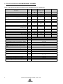
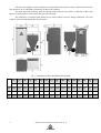
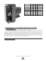
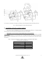
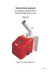
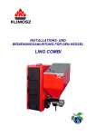
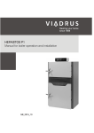
1
Operation and installation manual. 2014.11.12
1. Technical Data for KLIMOSZ MULTIDUO
Table 1. Dimensions and technical parameters of the KLIMOSZ MULTIDUO boiler.
kW
%
kW
Klimosz
MultiDuo
15
17 / 17
85,1
5,1 ÷ 17
Klimosz
MultiDuo
20
20 / 18,5
89,3
5,5 ÷ 18,5
Klimosz
MultiDuo
32
32 / 30
87,3
9,6 ÷ 30
kg/h
2,5
2,9
4,8
kg/h
kg/h
dm3
3,0
3,8
230
3,2
4,1
230
5,4
6,9
230
day
8,0
7,0
4,5
day
day
7,0
5,5
6,5
5,0
4,0
4,5
g/s
11
14
18
°C
kg
kg
m2
dm3
mm
Pa
bar
bar
bar
-
100 ÷ 170
3/3
425
435
2,1
70
160
10 ÷ 20
100 ÷ 170
3/3
510
525
3,1
92
160
10 ÷ 20
100 ÷ 170
3/3
540
560
3,5
105
160
15 ÷ 20
1,5 (version B 2,5)
2,2 (version B 3,7)
2 - wather
65 ÷ 80
Parametr
SI
Nominal power
Efficiency
Power regulation scope
Use of fuel at nominal power – continuous
heating
- pea coal
- brown coal
- pellets 18 MJ/kg
Storage bin volume
Approximate combustion time at nominal
power
- pea coal
- brown coal
- pellets
Flow of fumes in the smoke conduit - brown
coal - nominal power
Fumes’ temperature
Boiler class
Mass
Mass version B1 2,5
Heating area of the boiler
Water volume
Diameter of fumes outlet
Chimney draught
Water maximal working pressure
Water minimal working pressure
Water maximal trial pressure
Fluid group
Recommended working temperature for heating
water
Maximal working temperature for heating water
Minimal temperature of water returning to the
boiler
Maximal permitted level of heating material
Safety valve
Noise level
Connections of the boiler - heating and
returning water
Resistance of water flow through the boiler ∆t
= 20oC
Voltage
Electric energy consumption (fan / motor)
Electric energy consumption (shot light-option)
Electric insulation
°C
°C
90
50
°C
m
bar
dB
15 (version B 25)
1,5 (version B 2,5)
< 65 (A)
1½”
mbar
W
W
20 ÷ 30
230V / 50 Hz
180 / 80
400
IP 40
Operation and installation manual. 2014.11.12
2
2. Technical Data for KLIMOSZ MULTICOMBI
Table 2. Dimensions and technical parameters of the KLIMOSZ MULTICOMBI boiler.
Klimosz
MultiCombi
32
30 / 25
84,7
9,6 ÷ 32
kg/h
3,1
4,9
kg/h
3,7
5,6
dm3
230
230
day
7,0
4,0
day
5,5
4,0
g/s
11,7
17
°C
kg
m2
dm3
mm
Pa
bar
bar
bar
-
100 ÷ 210
4
490
40
156
10 ÷ 20
100 ÷ 220
3
520
50
156
15 ÷ 20
SI
Nominal power
Efficiency
Power regulation scope
Use of fuel at nominal power – continuous
heating
- pea coal
- brown coal
Storage bin volume
Approximate combustion time at nominal power
- pea coal
- brown coal
Flow of fumes in the smoke conduit - brown coal
- nominal power
Fumes’ temperature
Boiler class
Mass
Heating area of the boiler
Water volume
Diameter of fumes outlet
Chimney draught
Water maximal working pressure
Water minimal working pressure
Water maximal trial pressure
Fluid group
Recommended working temperature for heating
water
Maximal working temperature for heating water
Minimal temperature of water returning to the
boiler
Maximal permitted level of heating material
Safety valve
Noise level
Connections of the boiler - heating and returning
water
Resistance of water flow through the boiler ∆t =
20oC
Voltage
Electric energy consumption (fan / motor)
Electric energy consumption (shot light-option)
Electric insulation
3
kW
%
kW
Klimosz
MultiCombi
20
20 / 16
84,5
6,0 ÷ 20
Parametr
4,0
5,9
2 - woda
65 ÷ 80
°C
°C
90
50
°C
m
bar
dB
30
4,0
< 65 (A)
2” lub 6/4” GZ
mbar
0,4 ÷ 20
W
W
230V / 50 Hz
180 / 80
400
IP 40
Operation and installation manual. 2014.11.12
3. Construction of a KLIMOSZ MULTIDUO boiler
The KLIMOSZ MULTIDUO automatic boiler is not maintenance-free and requires the user to carry
out some periodic maintenance activities; it is therefore recommended that the user should carefully read the
principles of its operation, regulation and maintenance in order to avoid any problems related to its working.
The main part of the boiler is a steel heat exchanger, made from 6-8 mm thick internal sheet. In the
bottom part of the exchanger there is a combustion chamber with a chute (horizontal) burner and fire-resistant
catalyst. The fire-resistant catalyst stabilises the burning process, reduces emission of particulates from ash and
radiates heat back to the burner, thereby facilitating the complete burning of the fuel. Under the combustion
chamber there is an ash pan. The boiler door is constructed in a way that allows to open it from left to right
(hinges on the left of the exchanger, the handle on the right). KLIMOSZ MULTIDUO boilers can be also
installed in a closed system up to working pressure 1,5 bar (standard version) or on special order in the B
construction up to pressure 2,5 bar.
Next to the boiler, there is a fuel storage bin with a feeder screw at the bottom. The ash pan capacity is
suited to the capacity of the fuel bin, i.e. the ash pan should be filled with ash after fuel from the bin – pea grade
coal – has been burnt. There is a water tank behind the fuel bin for extinguishing the fuel bin in an emergency
(when the boiler is fired with pea grade coal) or the connector for mounting a thermostatic valve (required when
the boiler is fired with biomass). The connector is installed only when a boiler for pellets is ordered. The water
tank of the emergency extinguisher opens onto the feeder screw.
The fan which provides air for combustion is situated before the fuel bin and is connected with a
burner. The amount of air for combustion can be regulated by changing the fan rotation speed on the boiler
regulator (recommended) or by manual setting of the choking flap on the fan.
The heating water inlet is situated on the back wall of the exchanger, in its bottom middle; the water
outlet is situated on the top left and right. In the back of the boiler there is a smoke conduit, which carries flue
gas to the chimney. The steel exchanger, its cover as well as lower and upper door, are covered with mineral
insulation, which reduces heat loss during combustion. The steel casing is protected with high quality powder
paint.
4. Construction of the KLIMOSZ MULTICOMBI boiler
The KLIMOSZ MULTICOMBI automatic boiler is not maintenance-free; it is therefore
recommended that the user should carefully read the principles of its operation, regulation and maintenance in
order to avoid any problems related to its work. Construction of the KLIMOSZ MULTICOMBI boiler makes it
possible to use solid fuels in the automatic or traditional mode. The boiler has been constructed on the base of a
cast-iron exchanger of the multi-purpose VIADRUS U22 boiler. The cast-iron part of the boiler, which is called
the upper combustion chamber, can be used for burning coal, coke or wood as substitute fuel after manual fuel
loading. KLIMOSZ MULTICOMBI boilers can be installed also in a closed system up to working pressure 4,0
bar.
Under the water grate of the boiler heat exchanger of a U22 boiler, there is an added steel combustion
chamber, with (W version) or without (S version) a water jacket. There are the chute (horizontal) burner in the
lower combustion chamber. Fuel burning (pea grade coal, pellets) in automatic mode takes place in the lower
chamber. Under the combustion chamber there is an ash pan.
Next to the boiler, there is a fuel storage bin with a feeder screw at the bottom. The ash pan capacity is
suited to the capacity of the fuel bin, i.e. the ash pan should be filled with ash after the entire fuel from the bin
has been burnt. There is a water tank behind the fuel bin for emergency extinguishing (when pea grade coal is
used as fuel) or a place for installing a thermostatic valve (required when pellets are used as fuel) – a protective
device in case flame gets to the fuel bin.
Operation and installation manual. 2014.11.12
4
The fan which supplies air for combustion is situated before the fuel bin and is connected to the mixer.
The amount of air is controlled electronically by the boiler regulator.
The inlet and outlet of heating water is situated at the back part of the boiler. At the back of the boiler
there is a smoke conduit, which carries flue gas to the chimney.
The exchanger is insulated with mineral wool, which reduces heat loss during combustion. The steel
casing is protected with high quality powder paint.
Fig. 1. Dimensions boilers KLIMOSZ MULTIDUO.
S
L
H
S1
S2
L1
L2
L3
H1
H2
Z1
Z2
P1
P2
U1
U2
[mm]
[mm]
[mm]
[mm]
[mm]
[mm]
[mm]
[mm]
[mm]
[mm]
[mm]
[mm]
[mm]
[mm]
[mm]
[mm]
15
1200
750
1385
550
600
630
125
590
1100
1300
178
90
70
275
55
105
20
1200
825
1555
550
600
725
100
710
1285
1300
178
90
70
275
55
105
32
1270
825
1555
620
600
725
100
710
1285
1300
178
90
70
275
55
105
5
Operation and installation manual. 2014.11.12
The dimensions of the flue height are given below:
Klimosz Duo 15
- 1260 mm
Klimosz Duo 55 ÷ 75
- 1760 mm
Klimosz Duo 25 ÷ 45 - 1420 mm
Klimosz Duo 100 ÷ 150 - 1920 mm
Fig. 2. Dimensions boilers KLIMOSZ MULTICOMBI.
S
L
H
S1
S2
L1
L2
L3
H1
H2
Z1
Z2
P1
P2
U1
U2
[mm]
[mm]
[mm]
[mm]
[mm]
[mm]
[mm]
[mm]
[mm]
[mm]
[mm]
[mm]
[mm]
[mm]
[mm]
[mm]
20
1180
795
1555
550
600
725
82
710
1140
1271
250
275
450
275
435
180
32
1180
900
1555
550
600
725
82
710
1140
1271
250
275
450
275
435
180
Operation and installation manual. 2014.11.12
6
A
B
C
Combustion
chamber
[mm]
[mm]
[mm]
[dm3]
MULTIDUO 15
320
394
360
45,4
MULTIDUO 20
285
475
360
48,7
MULTIDUO 32
285
475
430
58,2
410
340
350
48,8
410
435
350
51,7
MULTICOMBI
20
MULTICOMBI
32
5. Hand-fired furnace of the KLIMOSZ MULTIDUO and KLIMOSZ
MULTICOMBI boiler
The KLIMOSZ MULTIDUO and KLIMOSZ MULTICOMBI boilers provides the possibility for
burning solid fuels in the traditional mode. After manual loading, wood and coal, as substitute fuel, can be burnt
in the upper part of the exchanger, called the "upper combustion chamber". The upper combustion chamber is
an emergency chamber, in which burning throughout the heating season is not recommended due to the lower
power capacity achieved as compared to the maximum power capacity of the boiler. For burning in the upper
chamber to run properly, some conditions for chimney draught have to be met.
NOTE No alterations in the furnace chamber may be made which could negatively affect the life-span of
the boiler or flue gas emission.
7
Operation and installation manual. 2014.11.12
1: Air mixer, 1: Secondary air jets (pipes), 3: Primary air inlet, 4: Inspection hole, 5: Hole flap, 6: Screws
Fig. 3. Schematic diagram of a chute (horizontal) burner.
6. Installation of the fire-resistant catalyst
The ceramic catalyst in KLIMOSZ boilers consists of rectangular plates (Table no. 3). The plates should
be put on shelves above the retort burner through the lower door of the ash pan.
When pellets are used as fuel, the catalyst should be put on lower projections.
ATTENTION! The boiler must not be operated without ceramic catalysts in the retort furnace, as it leads
to accelerated depositing of soot on the boiler due to incomplete burning, and to quicker wearing of the
boiler’s steel parts. Burning pea grade coal with the catalyst in the low position (lower shelf) may result in
damaging it.
Table 3. Dimensions and number of catalysts (chamotte) in a KLIMOSZ MULTIDUO,
KLIMOSZ MULTICOMBI boiler.
Boiler
KLIMOSZ MULTIDUO
Klimosz MultiDuo 15
Klimosz MultiDuo 25
Klimosz MultiDuo 35
KLIMOSZ MULTICOMBI
Klimosz MultiCombi 20
Klimosz MultiCombi 32
Plate 1 [mm]
345 x 220 ceramika
345 x 220 ceramika
400 x 320 ceramika
Chamotte plate
3 pc
4 pc
Operation and installation manual. 2014.11.12
8
Fig. 4. Position of ceramic catalyst on the exchanger shelves in a KLIMOSZ MULTICOMBI.
7. Lighting the boiler
The boiler may be operated only by adults, who know the principles of its operation, and who follow this
Operation Manual.
The following should be done before the boiler is lit:
• check whether there is enough water in the central heating and domestic water systems;
• check whether the grate, ash pan and flue conduits are clean;
• remove the ceramic catalysts from the retort furnace chamber;
• put the protective plate on the retort burner (this prevents lighting the fuel in the retort burner as a result of
embers falling down from the upper grate to the ash pan);
• when burning in the upper chamber in the hand-firing mode, remove fuel from the retort in order to properly
supply air for combustion. When burning is continued for more than two weeks, fuel should also be removed
from the bin;
• switch on the hand-firing mode – “hand firing” in the burning type options on the regulator.
Put firelighter (paper) and wood through the charging door over the entire grate area. Light the
firelighter through the door of the combustion chamber. Close the door and open slightly the ash pan door,
providing air supply to the combustion chamber. Put a layer of fuel onto the burning wood. After lighting the
fire, switch the regulator to the hand-fire mode, set the desired temperature and close the ash pan door. When
the fuel is burning well, stoke the fire by putting in another portion of fuel (switch off the blow-in fan on the
regulator when loading in fuel) Attention!!! No flammable liquids can be used and the boiler cannot be
overheated when lighting the fire. No flammable materials can be left near the boiler.
8. Boiler operation
Fuel should be topped up as needed and in accordance with the intensity of burning. Fuel should be
added evenly so that it does not form a pyramid. Ash and slag should be removed from the grate only when it
starts to hinder combustion. The procedure should be interrupted when, during the grate cleaning with a hook,
embers start to fall down to the ash pan.
In the evening, before burning in the boiler during the night, the grate should be cleaned thoroughly. In
the morning, after night burning, remove caked coal with a hook to clear the air supply. Put some fuel onto the
embers and do not remove ash and caked fuel from the grate until the fuel is burning. Then add fuel until the
combustion chamber is full. Each time you check the amount of fuel in the combustion chamber and each time
before stoking the fire, switch off the fan on the regulator (preferably by switching off the regulator) and delay
opening the loading door until the fan stops; the door is leak-tight and you should first loosen it slightly, wait
until pressure in the combustion chamber equalises and only then can you open the door fully. This will prevent
9
Operation and installation manual. 2014.11.12
hot flue gas from being blown out into the boiler room. The lower door of the furnace, the door of the lower
combustion chamber and the loading door must be tightly closed during the boiler operation.
NOTE: When opening any of the boiler's doors, stand in such a way as to prevent any hot gas from the boiler
from causing harm to you or to anyone standing nearby.
Adding more fuel – switch off the fan first (preferably by switching off the regulator). After the fan is
switched off and stopped, open the lower door of the boiler. Open the upper door of the boiler after a while,
unsealing it first, and put in a layer of fuel. After the upper and lower door is closed, switch on the fan by
pressing the button (as above). The boiler is now in normal operation mode. Do not add too much fuel as it may
cause the boiler to overheat quickly and it negatively affects the boiler's parameters as well as the parameters of
emission of hazardous substances in flue gas.
9. Boiler maintenance
Remove ash to non-flammable, closed containers with increased resistance to corrosion (for example
zinc-plated). The boiler can be cleaned only after it has been extinguished and cooled down!!! Cleaning the
walls of the upper combustion chamber can be easily done through the open upper door. Cleaning the smoke
conduits is done through the inspection hatch under the casing (the same as cleaning in automatic mode). The
boiler can be cleaned with the cleaning tools supplied with it. A boiler that has been soiled with tarry substances
should be cleaned in two steps. First, tarry deposits should be burnt out with suitable agents (for example
Sadpal), and then the heat exchange areas should be cleaned with a brush. Cleaning semi-liquid tarry deposits
results in damage to the brush and is ineffective, resulting only in spreading the tar over the boiler surface.
After the boiler surface and smoke conduits have been cleaned, close the inspection hatch tightly.
NOTE: Avoid accumulation of tarry deposits and soot on the heat exchanger areas and in smoke conduits. This
reduces the boiler’s efficiency and poses a serious hazard of soot and tar ignition in the chimney duct, which
usually results in damaging the chimney and even the building walls and in fire.
Take care to make the boiler leak-tight (combustion chamber door, ash pan door, mixer cleaning hole,
fuel bin cover, etc.) in order to avoid flue gas being expelled from the boiler into the boiler room.
If the boiler is not in use for more than 2 days (for example, after the heating season), it must be cleaned
and the fuel bin and the fuel feeding system emptied of fuel. Leave the boiler with the doors and
inspection hatch covers open to enable its ventilation and to avoid moisture condensation on the steel
surfaces of the boiler.
Operation and installation manual. 2014.11.12
10