Transcript
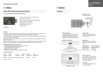
ingenium www.ingeniumsl.com autonomous detectors · SR · SR Hidden 360º Radiofrequency Detector Installation 85V-250V~(50/60Hz) For movement detection with concealed installation. 1 2 3 4 L N Min. 13 · SR 360° • Detects movement through solid, non-metallic objects. (brick, wood, etc). Patentado Patented • Detects minimum movements. Exento Licencia (Frec. Funcionamiento 9,9GHz) Licence Exempt (Working Frecuency 9.9GHz) ángulo de detección detection angle N 1.5W@ 230V 50Hz 85V-250V~(50/60Hz) L Potencia Máx Max. Switching Power 2200W Cos Ø= 1 880W Cos Ø= 0.6 400W Cos Ø= -0.6 17 85V-250V~(50/60Hz) N.O. 4 • Autonomous operation (no BUSing® required). 1 • Automatic reset after detection. 2 • Adjustable timer from pulse to 17min. ingenium • Adjustable sensitivity up to 12m www.ingeniumsl.com • Size: 100x75x35mm Detection Microprocessor Supply 4: Neutral 3: Phase 1: Load Description This is an autonomous device (no BUSing®required). It is designed to be connected to the lighting in transit areas, such as bathrooms, hallways or corridors and garages and installed in false ceilings and walls. Its hidden installation makes it immune to vandalism. It can detect objects through non-metallic solids by using radio frequency technology. It is superior to infra-red detectors, from sensitivity to precision. It is practical, unobtrusive and easy to install and adds elegance to your lighting design. Installation in a false ceiling Applicable power supplies depending on the load* SR • Incandescent or halogen lamp 220V .......................................................... 2000W • Incandescent 12V lamps containing mechanic transformer .......................... 1300W • Incandescent 12V lamps containing electronic transformer ........................... 900W • Fluorescent lamps not compensated ............................................................ 900W • Fluorescent lamps compensated Low factor ................................................. 400W High factor ................................................... 58W - 3µF Adjust. Nor 2 1 Mx Min Timer adjustment (Min.) ¥ The timer adjuster regulates the time a load remains connected. ¥ Timers can be adjusted between 0.25secs (Pulse) and 17mins, at 4sec intervals. ¥ Minimum timings are obtained by turning the adjustment potentiometer clockwise. SR output wiring Power consumption 4.5mA • Hidden installation in false ceilings or walls. 3 7 Sensitivity adjustments (Adjust.) ¥ The sensitivity adjustment limits the degree of detection. ¥ Maximum distances that can be reached will depend upon the density of obstacles to penetrate (wood, plaster, brick, etc.). Detection area The detection area must face the room, with the silk screened part of the device face-down. Detection area at 2.5m from the floor: Guaranteed: 6x3m Maximum: 12x6m The device can be partially blinded with metal tape to cancel detection in a zone/direction. Floor *Estimated power calculated with the losses of each type of lighting. Technical Characteristics Device Voltage Reference Supply SR 85-265V AC * voltage free, normally open relay. Power Consumption Maximum Detection Area Secure Adjustment Detec. Area Parameters 4.5mA @ 230V AC 12x6m 6x3m Sensitivity/Time Num. Outputs Switching capacity 1* 10A Guaranteed area 6x3m Maximum area 12x6m Length side of the room Direction of the device Place lengthwise, with the length of the device parallel to the length of the room. Together with the programming, this will ensure optimal detection. Do NOT install: á In locations susceptible to vibrations. á Over fluorescent lights.