1
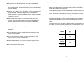
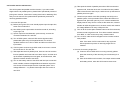
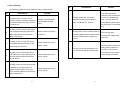
4. Inverter LED (green): To indicate the UPS is powered through
4.
Connection and Installation
The system may be installed and wired only by qualified electricians in
inverter.
accordance with applicable safety regulations!
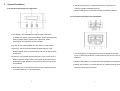
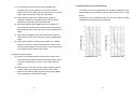
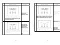
5~9. Load & Battery Capacity LEDs:
(a) No. 5 to 8 LED is green color and No. 9 (used as warning
4.1 Unpacking and Inspection for 6K/10K
LED for overload or battery low) is yellow.
(b) These LEDs show the load % of the UPS if the mains power
1. Unpack the packaging and check the package contents. The
is available (in normal operation). LEDs light up to indicate
shipping package contains:
the following information.
z
A UPS
z
A user manual
z
A communication cable
No. 5 LED: 0-25 %
No. 5&6&7&8 LEDs: 76-100 %
No. 5&6 LEDs: 26-50 %
No. 5&6&7&8&9 LEDs: Overload
2. Inspect the appearance of the UPS to see if there is any damage
No. 5&6&7 LEDs: 51-75 %
during transportation. Do not turn on the unit and notify the carrier
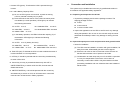
(c) In the battery operation, the LEDs indicate the capacity (%) of
the batteries. LEDs light up to indicate the following
and dealer immediately if there is any damage or lacking of some
parts.
information.
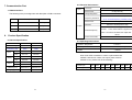
4.2 Input and output power cords and protective earth ground installation
No. 9 LED: 0-25 % (battery low level)
No. 8&9LEDs: 26-50 %
No. 6&7&8&9 LEDs: 76-95 %
No. 7&8&9 LEDs: 51-75 %
No. 5&6&7&8&9 LEDs: 96-100 %
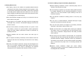
1. Notes for installation
(a) The UPS must be installed in a location with good ventilation, far
away from water, inflammable gas and corrosive agents.
10. Fault LED (red): To indicate the UPS is in fault condition because of
inverter shutdown or over-temperature
11. OFF key: It should be pressed with the control key simultaneously
(b) Ensure the air vents on the front and rear of the UPS are not
blocked. Allow at least 0.5m of space on each side.
(c) Condensation to water drops may occur if the UPS is unpacked
in a very low temperature environment. In this case it is
to switch off the UPS.
necessary to wait until the UPS is fully dried inside out before
12. Control key: this key is pressed simultaneously with OFF or
ON/TEST/MUTE key to switch on/off the UPS, do auto-test and
proceeding installation and use. Otherwise there are hazards of
electric shock.
disable the buzzer.
13. ON/TEST/MUTE key: It should be pressed with the control key
simultaneously to switch on UPS, do UPS auto-test in normal AC
mode and turn off the buzzer in battery operation.
8
9