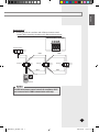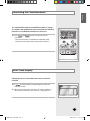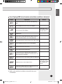
1
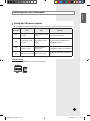
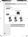
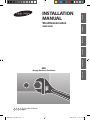
ENGLISH INSTALLATION MANUAL Wired Remote Control PORTUGUÊS ITALIANO FRANÇAIS ESPAÑOL MWR-VH01 ERV DEUTSCH (Energy Recovery Ventilator) E S F I P D DB98-27509A(2) MWR-VH01_E_IM_27509.indd 13 2007-09-18 ソタネト 3:55:38 Safety Precautions This Installation manual indicates you to install the ERV wired remote control which is connected to ventilator. To install other optional accessories, refer to an appropriate installation manual. WARNING CAUTION Do not install the unit by yourself. Incorrect installation of the unit could cause injury due to fire, electric shock and water leakage or the unit falling. Consult a dealer or a qualified installer. Install the product with rated power supply. Do not attempt to repair, modify or disassemble the unit on your own. Make sure that these installations are carried out by qualified personnel to avoid electric shock or fire. The electric work must be done by service agent or similarly qualified person according to national wiring regulations and use only rated cable. If the capacity of the electric work is not properly completed, electric shock or fire may occur. Install the unit in a place where it is strong enough to hold the product weight. When installed in place where it is not strong enough to withhold the product weight, the unit may fall and cause injury. Do not attempt to move or reinstall the unit on your own. There is a risk of electric shock or fire. Read carefully this installation manual before installation and check whether the unit is installed correctly after installation. Consult you dealer when you need to dispose of the unit. Do not install the product in a place where it is exposed to inflammable gas leakage. Do not spill any kind of liquid into the unit. It may result in electric shock or fire. Install the unit where there is 0°C to 39°C without being exposed to direct sunlight. Do not press the unit with a pointed thing. Do not install the product in the place where exposed to sulfurous acid or steam because it may damage the parts or cause malfunction. Install electrical wires not to get tension. There is a risk of being torn which cause fire. Do not install the unit in a place there is exposed to acid or alkaline liquid or special chemical spray. Do not connect the power plug to electrical wires. It may result in fire. Make sure that the unit does not affect to other devices in special environment such as hospital. E-2 MWR-VH01_E_IM_27509.indd 2 2007-04-18 ソタネト 5:16:05 ENGLISH Contents ACCESSORIES ................................................................................................... 4 INSTALLING THE UNIT .................................................................................... 4 Installation ................................................................................................ 4 Setting Up PCB Option Switches Installation Examples .................................................. 5 .......................................................................... 6 INITIALIZING THE COMMUNICATION ............................................................ 9 ERROR CODE DISPLAY ................................................................................... 9 E-3 MWR-VH01_E_IM_27509.indd 3 2007-04-18 ソタネト 5:16:05 Accessories The following accessories are supplied with the ERV wired remote control. The number of each accessory is indicated in parentheses. M4X16 tapped screw(2) User’s manual(1) Installation manual(1) Caution The ERV wired remote control must be installed by qualified installers. Before installing the ERV wired remote control, make sure the main power is off. All cables must be installed according to the national wiring regulations and must be installed inside the wall to avoid user contact. Installing the Unit Installation Connect the power cables and communication cables of the ERV wired remote control to the terminal of ventilator PCB. ERV Wired remote control 1 Open the ERV wired remote control by using the groove on its top. 2 Secure the rear cover of the ERV wired remote control to the wall with 2 screws. 3 Connect the V1, V2 terminal of the ERV wired remote control to the V1, V2 terminal of the ventilator. 4 Connect the F3, F4 terminal of the ERV wired remote control to the F3, F4 terminal of the ventilator. 5 Reassemble the ERV wired remote control. Electrical wires (Not supplied) Ventilator PCB Caution The electrical wires and the power cable of ERV wired remote control should be installed separately. The ERV wired remote control may malfunction due to electric trouble. E-4 MWR-VH01_E_IM_27509.indd 4 2007-09-18 ソタネト 3:55:38 ENGLISH Installing the Unit (Continued) Setting Up PCB Option Switches S et up the DIP switches of the ERV wired remote control according to the user environment. DIP switch OFF ON Remarks SW1 Auto operation mode Auto operation mode Use only when the ventilator has not used auto operation function used SW2 Air purifying mode not used Air purifying mode used Use only when the ventilator has air purifying function SW3 External control mode not used External control mode used Use only when the ventilator is connected to system air conditioner SW4 Sleep mode not used Sleep mode used Classified by domestic/commercial use Default setting T he SW908 should be set as “0” under all conditions. E-5 MWR-VH01_E_IM_27509.indd 5 2007-09-19 ソタタ・10:41:12 Installing the Unit (Continued) Installation Examples Individual control C ontrolling 1 ventilator individually with 1 ERV wired remote control. ERV wired remote control PCB Master Ventilator Main : 0 RMC : 0 COM1 Ventilator Main : 1 RMC : 1 Ventilator COM2 COM1 Main : 2 RMC : 2 Ventilator COM2 COM2 Set as “0” Set as “0” ERV wired remote control ERV wired remote control Main : 3 RMC : 3 Set as “0” ERV wired remote control Caution The ERV wired remote control controls the ventilators which are connected to the COM2 communication cable only. E-6 MWR-VH01_E_IM_27509.indd 6 2007-04-18 ソタネト 5:16:07 ENGLISH Group control C ontrolling more than 2 ventilators with 1 ERV wired remote control. Example : When controlling 3 ventilators with 1 ERV wired remote control. ERV wired remote control PCB Master Ventilator Main : 0 RMC : 0 COM1 COM1 Main : 1 RMC : 1 Ventilator Ventilator COM1 Main : 2 RMC : 2 Ventilator Main : 3 RMC : 3 COM2 COM2 COM2 Set as “0” ERV wired remote control Caution The ERV wired remote control controls the ventilators which are connected to the COM2 communication cable only. E-7 MWR-VH01_E_IM_27509.indd 7 2007-04-18 ソタネト 5:16:07 Installing the Unit (Continued) Using 2-remote controls ‘2-remote’ means that 2 ERV wired remote controls are used to control 1 ventilator. Set the DIP switch of the ventilator PCB as seen in the picture. ERV wired remote control PCB Master Ventilator Main : 0 RMC : 0 COM1 Main : 1 RMC : 1 Ventilator COM2 Set as “0” ERV wired remote control (Master) Set as “1” ERV wired remote control (Slave) Caution 2-ERV wired remote controls control the ventilator which is connected to the COM2 communication cable. E-8 MWR-VH01_E_IM_27509.indd 8 2007-04-18 ソタネト 5:16:08 ENGLISH Initializing the Communication The communication between an individual ventilator or a group of ventilators and an ERV wired remote control must be initialized when there is an additional ventilator to be connected. Press and 3 seconds. buttons simultaneously for - The communication is initialized and the ERV wired remote control queries every connected ventilators. Error Code Display LCD displays the errors of the ERV wired remote control and ventilator. If is indicated, the corresponding error codes are indicated as well. When LCD displays the same error of several ventilators, the ventilator with the lower address is displayed first. E-9 MWR-VH01_E_IM_27509.indd 9 2007-04-18 ソタネト 5:16:09 Error Code Display (Continued) Error Display of ERV wired remote control Display Explanation Remarks Communication error between ERV wired remote control and ventilator (After the communication is cut off for continuous 3 minutes) - Communication error between MASTER ERV wired remote control and SLAVE ERV wired remote control (After the communication is cut off for continuous 3 minutes) - Communication Packet error - Tracking error between ERV wired remote control and ventilator over 10 times - Cross installation error of COM1/COM2 of ERV wired remote control - Communication error when both remote controls are set as MASTER No ventilators installed (No ventilators found after tracking) When using 2-remote control - Not yet installed the external device (The external device is not yet detected after setting up When using external device the option for external device and tracking) E-10 MWR-VH01_E_IM_27509.indd 10 2007-04-18 ソタネト 5:16:09 ENGLISH Error Display of ERV wired remote control when ventilator is detected Display Explanation Remarks Communication error for 3 minutes after detecting COM1 - Indoor temperature sensor error (Short/Open) - CO2 sensor error (Short/Open) Detected only by the ventilator which has CO2 sensor EEPROM error - Tracking error or MASTER ventilator (After 5 times of tracking, SLAVE ventilators can not be detected.) - System failure due to communication error after tracking - Outdoor temperature sensor error (Short/Open) - Supply Air fan motor sensor error - Exhaust Air fan motor sensor error - Communication error between ERV wired remote control and ventilator (After the communication is cut off for continuous 3 minutes) - Communication error by installing COM1 dual MASTER - Temperature sensor error (Open/Short) Damper error (When there is no switch input for 100 seconds while monitoring the damper) Detected only by the ventilator which has temperature sensor - Refer to the ventilator installation manual for the errors of ventilator. E-11 MWR-VH01_E_IM_27509.indd 11 2007-04-18 ソタネト 5:16:10 MWR-VH01_E_IM_27509.indd 12 2007-04-18 ソタネト 5:16:11