1
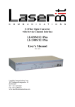
LaserBit Communications Corp.
Pico Manual
.
User's Manual
V4.51
Laser Bit PICO systems
LaserBit Communications Corp.
1037 Budapest, Kunigunda u. 45.
HUNGARY
Tel.: +36 1-453 7440, fax: +36 1-240-3570
V4.51
1
LaserBit Communications Corp.
Pico Manual
Table of contents:
1
Characteristics:.......................................................................................... 8
1.1
1.2
2
Optical free space transmission .............................................................. 10
2.1
2.2
2.3
2.4
3
Link path......................................................................................................................... 15
Installation sites............................................................................................................... 15
Distance determination .................................................................................................... 16
Direct sunshine................................................................................................................ 16
Eye safety........................................................................................................................ 17
Installation procedure ............................................................................. 18
5.1
5.2
5.3
5.4
6
7
2.1 System set-up overview ............................................................................................. 13
Key factors of operation .................................................................................................. 13
Site survey ................................................................................................ 15
4.1
4.2
4.3
4.4
4.5
5
Areas with natural or artificial obstacles .......................................................................... 11
Urban areas ..................................................................................................................... 11
Industrial areas ................................................................................................................ 12
ISP connections ............................................................................................................... 12
Installation procedures............................................................................ 13
3.1
3.2
4
Features............................................................................................................................. 9
Accessories ....................................................................................................................... 9
Installation of the link...................................................................................................... 18
The connection of the outdoor box................................................................................... 23
Mounting bracket fixing: ................................................................................................. 24
On-the-table test .............................................................................................................. 26
Warranty conditions................................................................................ 28
Twisted pair cabling ................................................................................ 32
V4.51
2
LaserBit Communications Corp.
Safety of the LaserBit product
Pico Manual
GB
The LaserBit is classified as Class 3B laser product.
The LaserBit System has been tested and found to comply with the EN 60825-1:1994
+A11:96 (laser safety), EN 60950-1:92+A1:93+A2:93+A3:95+A4:97 (electrical safety), EN
55022:1998 Class 3B (emission) and EN 55024:1998 and EN 50082-2:1995 (immunity)
European standards.
The laser radiation is emitted from the transmitter optics through the glass window in
the front side of the laser head under less than 10 mrad divergences. Depending on the
model, one, two or four of such transmitters may be present inside one head assembly.
The optical axles of the transmitters are parallel to each other, each of them emitting
laser radiation towards the same direction – onward through the optical window of the
head. No other aperture through which laser radiation can occur present in the laser
head.
Warning!
Invisible laser radiation! Looking directly into the laser beam can cause
permanent damage to the eye! Safe looking distance varies with beam
power and divergence. See attached data sheet for exact figures.
The LaserBit product should be installed in such a way that nobody can access the optical
window or can get in the way of the laser beam accidentally. For detailed instructions please
read Eye Safety part of chapter 2.3 of the manual (Site Survey).
The LaserBit product provided with all the necessary labels specified by the standards.
Moreover informative labels should be put on clearly visible places where the laser beam can
be accessed. The locations of the warning labels are shown in Chapter 2.3/Eye Safety.
The Indoor Interconnection Unit is assembled with a certified power cord, which must
be connected to the mains through a power outlet to make the disconnection possible
at any time. Any modification to the above installation is prohibited. If modifications
are required by the local standard, please contact the manufacturer.
To ensure the compliance with the EN 60950 safety requirements, only the
manufacturer or its certified partners should install the system.
Warning
Operating the LaserBit product other than described in this manual can cause
undesired laser radiation and can be dangerous to he eye or electrical shock!
V4.51
3
LaserBit Communications Corp.
Elektrische Sicherheit des LaserBit Produkts
Pico Manual
D
Das LaserBit ist eine Klasse 3B Lasereinrichtung.
Das LaserBit Produkt wurde geprüft und entspricht den Anforderungen der Europäischen
Standards
EN60825-1:1994
+
A11:96
(Lasereinrichtungen),
EN609501:92+A1:93+A3:95+A4:97 (Elektrische Sicherheit), EN55022:1998 Klasse 3B (EMV,
Störaussendung) und EN55024:1998 sowie EN50082-2:1995 (EMV, Störfestigkeit)
Der Laserstrahl wird von der Sendeoptik durch die Glasscheibe an der Frontseite des
Laserkopf mit einer Divergenz von weniger als 10mrad abgestahlt. Abhängig vom Modell des
Laserkopf können sich ein, zwei oder vier solcher Sender innerhalb des Laserkopf befinden.
Die optischen Achsen der einzelnen Sender verlaufen parallel zueinander wobei jeder Sender
in die gleiche Richtung stahlt - in Richtung der Optik des Laserkopf. Es sind keine weiteren
Blenden vorhanden durch die Laserstrahlen auftreten können.
Warnung!
Unsichtbare Laserstrahlen! Nicht direkt in den Lasertrahl schauen, da dies
die Augen permanent schädigen kann. Der Sicherheitsabstand variiert mit
der Laserleistung und Divergenz des Laserstrahl. Details hierzu sind im
Datenblatt nachzulesen.
Das LaserBit Produkt muß so installiert werden, daß niemand Zutritt zu der Optik des
Laserkopf hat oder zufällig in den Bereich des Laserstrahl kommen kann. Kapitel 2.3 auf des
Handbuchs enthält ausführliche Anweisungen zum Schutz der Augen.
Das LaserBit Produkt ist mit allen notwendigen Warnhinweisen versehen die durch die
Standards vorgebenen werden. Weitergehende Hinweise sollten an gut sichtbaren Stellen
angebracht werden wo man sich dem Laserkopf gefahrlos nähern kann. Die Positionen der
Warnhinweise sind auf Kapitel 2.3, Schutz der Augen
Die „Indoor Interconnection Unit“, die mit einem zertifzierten Netzkabel ausgeliefert wird,
muß mit der Stromversorgung verbunden werden, indem der Netzstecker in eine geeignete
Netzsteckdose gesteckt wird, womit die Lasereinrichtung auch jederzeit wieder vom Netz
getrennt werden kann. Jegliche Modifikationen an der Installation sind verboten.
Falls aufgrund nationaler Vorschriften denoch Änderungen an der Installation vorgenommen
werden müssen, ist vorher der Hersteller zu befragen.
Um die Konformität bezüglich der Elektrischen Sicherheit nach EN60950 sicherzustellen,
sollte das System nur vom Hersteller oder seinen zertifizierten Partnern installiert werden.
Warnung !
Die Inbetriebnahme oder der Betrieb des LaserBit Produkts, abweichend von den
Vorgaben dieses Handbuchs, kann unerwünschte Laserstrahlung verursachen und
gefährlich für die Augen werden oder einen elektrischen Schock verursachen.
V4.51
4
LaserBit Communications Corp.
Sécurité de produit LaserBit
Pico Manual
F
Le produit LaserBit est classifié dans la catégorie laser 3B.
Le système de LaserBit a été testé et correspond aux normes européennes: EN 608251:1994+A11:96 (sécurité du laser), EN 60950-1:92 + A1:93 + A2:93 + A3:95 + A4:97
(sécurité éléctrique), EN 55022:1998 Classe 3B (émission), EN 55024:1998 et EN 500822:1995 (immunité).
La radiation laser est émise à partir de l’émetteur optique à travers une fenêtre en verre
placée à la tête du laser et a une divergence de moins de 10 mrad. Selon le type de
modèle, le nombre d’émetteur placé dans la tête du laser varie entre 1, 2 ou 4. L’axe
optique des émetteurs sont parallèles et chacun d’entre eux émettent la radiation laser
dans la même direction, à travers la fenêtre de la tête du laser. Aucune autre ouverture
dans la tête ne peut laisser passer de radiation laser.
Attention!
La radiation laser est invisible! Interdiction de regarder le rayon laser ! Risques graves
de lésions pour les yeux! La distance de sécurité pour la vue est variable et dépend de la
puissance du rayon et de sa divergence! Consulter la feuille de données ci-jointe pour
calculs exacts.
L’installation de produit LaserBit doit être faite de sorte que personne ne puisse accéder à la
fenêtre optique ou traverser le rayon laser par accident. Pour instructions détaillées, lire la
partie Sécurité de l’œil dans le chapitre 2.3 du manuel (Site Survey) à la page 20.
Le produit LaserBit possède la totalité des étiquettes stipulées par les normes. De plus, des
avis informatifs sont placés à des endroits clairement visibles où le rayon laser pourrait être
accessible. Une liste des endroits où sont placés les avis informatifs est donnée dans le
chapitre 2.3 du manuel (Eye Safety) à la page 21.
Le boîtier de connections intérieure (Indoor Interconnection Unit) est fournit avec un
fil éléctrique certifié par lequel l’appareil est connecté à la prise de courant. Grâce à
cela, il est possible de débrancher à n’importe quel moment. Il est formellement
interdit d’apporter de quelconques modifications à cette installation. Si une
modification est cependant nécessaire à cause des normes locales, contacter le
fabricant.
Attention!
Tout opération consistant à utiliser le produit LaserBit de façon différente que celle
indiquée dans le manuel pourrait engendrer des effets indésirables du rayon laser, être
dangereuse pour la vue et provoquer un choc éléctrique!
V4.51
5
LaserBit Communications Corp.
Sicurezza dei prodotti LaserBit
Pico Manual
I
LaserBit e classificáto di essere un Classe 3B prodotto di lazer.
Il sistema LaserBit e stato collaudato e trovato conforme con EN 60825-1:1994 +A11:96
(sicurezza sul prodotti lazer), EN 60950-1:92+A1:93+A2:93+A3:95+A4:97 (sicurezza
eletrica), EN 55022:1998 Class B (emissione) ed EN 55024:1998 ed EN 50082-2:1995
(immunitá), Norme Europee.
La radiazione lazer viene emissa dalla ottica del trasmettitore via la finestra di vetro
posizionata sulla fronte della testa di lazer con una divergenza minore di 10 mrad.
Secondo il modello si trovano uno, due o quatro transmettitori in una testa di lazer.
Gli assi ottici dei trasmettitori sono paralelli uno con l’altro, tutti quanti emmittono il
raggio di lazer nella stessa direzione via la finestra ottica della testa lazer. Non esiste
nessun’ altra appertura attraverso quale radiazione di lazer puó presentarsi.
Avvertimento!
Radiazione lazer invisibile! Guardando direttamente nel raggio di lazer puó
causare danni permanenti degli ochhi! La distanza di sicurezza dello
sguardo varia secondo la potenza e la divergenza dello raggio di lazer.
Distanza di sucurezza viene communicato sulla pagina tehnica allegata.
Prodotti LaserBit devono essere installati in tale maniera, che nessuno possa accedere la
finestra ottica o esporsi al raggio di lazer per caso. Per informazioni piu detagliati vedi la parte
Sicurezza Ochhi del capitolo 2.3 nel manuale sulla pagina 20.
I prodotti LaserBit veranno forniti con tutte segnalazioni previste nelle norme. In addizione
segnalazioni informative devono essere posizionate nel posti ben’ visibili dove il raggio di
lazer puó essere accesso. Le locazioni delle segnalazioni di sicurezze sono demostrati sulla
pagina 21 del manuale (Capitolo 2.3/ Sicurezza Ochhi)
La Unitá Interconnezione Interna viene fornita con un cavo di allimentazione
certificato quale deve essere collegato con la rete di potenza tramitte una presa per
assicurare la separabilita in qualsiasi momento. Qualunque modifica sul questo
impianto e proibito. Se modifiche si devono eseguire per rispettare la norma locale, si
priega di contattare il produttore.
Per garantire la conformitá con la norma EN 60950, il sistame deve essere installato
dal produttore o dai partner certificati.
Attenzione!
Qualsiasi operazione di LaserBit diversa di quello descritto in questo manuale puó
causare non desiderata radiazione lazer e puó essere pericoloso per gli ochhi o causare
scossa electrica!
V4.51
6
LaserBit Communications Corp.
!
Pico Manual
Safety 3B Class Laser device
This unit complies with the relevant safety regulations. If you have questions
please contact Laser Bit Communications Co. tech support.
? Fragile handle with care.
? Ensure that the local main voltage is within the range of 100VAC to
240VAC
? Ensure that no liquids are dropped inside the unit.
? In the case of emergency (e.g.: damaged casing, elements or cables)
disconnect the unit immediately.
? Only qualified technicians should repair the device. Unauthorized opening
will result in warranty being void.
This manual will show you how to install and use the Laserbit PICO systems
V4.51
7
LaserBit Communications Corp.
Pico Manual
1 Characteristics:
Model Number
Interfaces
Pico Ethernet
Ethernet, Fast-Ethernet
Distance in meter
Electrical & Optical Characteristics
XMT Power mW
(max)
Transmitter
Wave Length (nm)
Dynamic range
Power
Power to Head
V4.51
150
65 mW
Laser Diode
780 to 980
>25dB
110/220 VAC, 50W max.
Environments
Operating
Temperature
Storage
Temperature
Humidity
Physical Characteristic
Housing
Protective Shield
Weight (kg)
Dimension (mm)
75
-25 – 60 Centigrade (normal version)
-40 – 85 Centigrade (extended version)
-40 – 80 Centigrade (normal version)
-55 – 105 Centigrade (extended version)
Up to 95% non condensed
Metal
Hardened Aluminium, with white reflective paint and Stainless steel
Base
2,5 Kgs
160X110X350
8
LaserBit Communications Corp.
Pico Manual
1.1 Features
? The newly developed „Pico” used for transmit 100 Mb/s data up to 150
meters.
? Easy to install, and easy to use.
1.2 Accessories
? 2 Pico Units
? 2 Mounting Brackets
? 2 Outdoor Interconnection Unit
The LaserBit-Pico product range offers cost effective, reliable free space laser
transmission for 100Mbps Ethernet data through free space.
The transmission technique used in the LaserBit devices provides transparent
wire speed data transfer with virtually zero latency, because it uses infrared light
as a transmission medium, LaserBit systems do not require frequency licenses
and the transmission is not affected by electro-magnetic interference or radio
frequency interference. The LaserBit Pico link can be considered as a virtual
fiber in the air, with standard Cat 5 connection at each end.
Each product is built using highest quality electronic components for operation
in even the most adverse conditions. Metal housing gives a robust, waterproof
environment for the electronics, with IP65 isolation rating. The shield protects
the device from direct sunlight and provides extra air isolation.
Invisible laser radiation, Class 3B laser product. Looking directly into the
laser beam can cause permanent damage to the eye!
V4.51
9
LaserBit Communications Corp.
Pico Manual
2 Optical free space transmission
The principle used in free space laser transmission is very similar to the one is
used for fiber optic transmission. The difference is while fiber optic devices use
electronics and optics optimised for optical fiber, free space communication
equipment deploys electronics and optics optimised for transmission through the
air. Also you can observe the similarity in the transmission properties. No
galvanic contact, no ground loops, no need for surge protection, noise immunity,
high bandwidth.
What makes it unique – and difficult to design – is that it does not require any
transmission medium like fiber or copper, but has to cope with the dynamically
changing parameters. For instance while the attenuation of an optical fiber is
constant, the attenuation of the atmosphere between the laser units can change
dramatically (depending on the weather conditions).
The LaserBit heads are usually placed on top of buildings, where clear line of
sight is guaranteed and the beam cannot be interrupted.
In the head the incoming signal is amplified, encoded, then drives the laser
diode. The transmitter optics assures the proper beam shape. The receiver optics
perceives and directs the transmitted signal to the photodiode. The diode
converts it back into electrical, then it is decoded, amplified and converted.
There are several things that can influence the quality of transmission. We can
classify those factors into three main groups.
? System conditions - transmitting power, transmitters wavelength, beam
divergence, receiver optics diameter, receiver sensitivity, parameters of
optical system and casing. These parameters determine the system’s
characteristic at a certain distance and are controlled by system design and
factory set up.
V4.51
10
LaserBit Communications Corp.
Pico Manual
? Weather conditions - molecular absorption, particle scattering and
turbulence. These elements have great effect on the operational conditions
of the system. We do not have very much influence on them; proper
product selection can eliminate the undesirable effects.
? Environmental conditions - building movements, direct sunlight,
refractive surfaces. These are also key factors related to the installation
sites and can be controlled by appropriate site survey and system
installation.
Most typically the LaserBit-Pico is used to interconnect LAN-s, or computers.
The system is protocol transparent, thus other applications also can be taken into
consideration. Appropriate interface converters are needed and system
bandwidth must be matched for that.
Here we collected some circumstances, where the employment of the LaserBit
is the most adequate and cost effective solution. Those are:
2.1 Areas with natural or artificial obstacles
Where cable is actually not an alternative, like across rivers or railways or
in rugged terrain.
2.2 Urban areas
Where only leased lines are available with limited speed and high rental
cost. With LaserBit links you can establish on line LAN-to-LAN
connections.
V4.51
11
LaserBit Communications Corp.
Pico Manual
2.3 Industrial areas
Where you have noisy environment with high EMI or RFI. Factory
buildings, airport objects can be connected through laser link.
2.4 ISP connections
Where high bandwidth is required. ISP’s can offer high-speed links to their
customers or trunks can be established between ISP’s instead of expensive
leased lines.
Corporate
LAN
V4.51
ISP
12
LaserBit Communications Corp.
Pico Manual
3 Installation procedures
3.1 System set-up overview
The set up of a LaserBit link needs careful planning, thorough site
preparation, and accurate installation. We have listed the work that is essential
for a successful system set up.
1. Site survey
2. System design
3. Site preparation
4. System installation
5. Alignment procedure
6. System test
We deem necessary to emphasize the importance of site survey. It is
fundamental to make sure if the laser link is a viable solution at all. Most
customers usually are not experts in this field, so they cannot realize the
sources of possible difficulties. It is also very important to clarify the position,
size and outlook of the support frame with the customer in advance.
3.2 Key factors of operation
There are four key issues that the site survey. The proper system operation
cannot be guaranteed without satisfying all the four requirements.
a. Clear line of sight - first of all optical path between the two ends must
be free of any obstacles. It not only means that one has to see the other
side, but other possible sources of disturbance should also be taken into
consideration. For example there might be turbulence above the roofs and
other constructions, and this can cause fraction or scattering of the beam
or snow accumulation on roofs too close to the beam can influence or
even interrupt the communication.
b. Solid mount surface - is the key for long-term operation. Since the
diameter of the beam is limited, it is extremely important to mount the
unit on a stable structure with the possible smallest movement. This way
the receiver of the remote unit cannot get out of the beam due to the
movement of the opposite head.
V4.51
13
LaserBit Communications Corp.
Pico Manual
d. East-West orientation - although the receiver optics is equipped with
optical filters to protect the receiver diode from the effect of undesired
light sources, the direct sunshine can cause saturation of the diode. This
prevents the system from working properly for several minutes a day in a
certain time of the year. There are some methods to reduce the effect of
the sun, but the best way is to avoid the East-West orientation wherever it
is possible.
V4.51
14
LaserBit Communications Corp.
Pico Manual
4 Site survey
In order to comply with the requirements of the successful installation including the discussed four key factors and other criteria - the following
matters should be taken into consideration.
4.1 Link path
If the clear line of sight is available, further examination of the sites and
optical path is necessary after possible sources of temporary or periodic
malfunction. No chimneys, steam or other smoke sources may be present
under or near to the beam path. They can weaken the strength of the signal or
can cause wandering of the beam. Heater vents and air conditioners have
similar effect as they can cause air turbulence. Scintillation from rooftops or
glass surfaces due to direct sunshine also may interrupt the beam. The closer
the source to the transmitter the greater it’s effect. Because both sides have
transmitter and receiver, the source of such symptoms in the middle has the
less effect on the overall system. If there are trees near the transmission path,
consideration of growth and the wind blown leaves into the into the
transmission path is necessary. Areas under construction can have moving
obstacles like construction cranes that can disturb the communication.
4.2 Installation sites
All buildings and constructions have a certain movement of their own. It’s
determined by the structure and material of the building. Metal structures can
shift or twist due to temperature changes. Wooden construction can expand or
shrink with the changing of humidity. Give preference to concrete or brick
buildings. On the other hand high structures like towers, skyscrapers or poles
always subject to great movement. Mount the support frame to basic holders
of the building or near corners, as they are the most stable spots. Use
appropriate consoles for wall mounting. If a stand is used on the top of a
building, secure it directly to the ceiling or to the concrete cornice wherever is
possible. Do not fix stands to insulating materials as they can slowly sink
under the weight of the unit and with temperature changes. Big chimneys and
smokestacks may look stable, but as their inner temperature varies they can
also move. Vibration caused by heavy traffic, trains, elevators, etc. may
slowly move the system out of its specified direction. Another important
consideration is to provide enough space for alignment and to have the
potential for future maintenance. Consider that the support frame is usually
heavy, so the selected spot should be easily accessible.
V4.51
15
LaserBit Communications Corp.
Pico Manual
It is not only the building that has to be solid, but the support structure too.
Antenna poles, security camera holders are not suitable for the LaserBit units.
A catalogue of more than 80 mounting frames can be ordered from the
manufacturer (both available in printed and CD ROM format. Please contact
with Laser Bit Communications Co. tech support for details.
Preferred installation sites
Concrete wall
Brick wall
Pay attention to
Behind window
Old constructs
Microwave towers
Avoid (*)
Soft materials
Chimneys
Wooden constructs
Metal masts or Frames
Hidden heat isolations, like
Styrofoam
(*)
In cases where installations are listed under “AVOID” cannot be avoided than special mounting accessories to
be designed and special installations must be used.
4.3 Distance determination
Try to get as accurate information about the connection distance as you can in
order to get the maximum performance out of the system. The easiest way is
to obtain a proportional map and calculate the distance. In some cases the
distance between sites can be measured directly with distance recorders.
There are infrared and laser distance meters that can display the distance
between the viewer and the defined point.
4.4 Direct sunshine
To prevent the sun shining directly into the receiver optics, first one has to
determine the orientation of the link. Try to avoid East-West orientation
wherever it is possible. Examine both sides of the link at sunset and sunrise
and find a position where the sun cannot shine directly into the receiver. Be
aware that the path of the sun is changing throughout the year
V4.51
16
LaserBit Communications Corp.
Pico Manual
4.5 Eye safety
No two installations sites are the same. The buildings or structures, the
available space and the accessibility of the place will be different in each case.
Nevertheless, as a general rule it is very important to select the installation
site so, that nobody can look directly into the transmitter. For this reason
place the head either so high (on the side wall of the building) or so close to
the edge of the building (on a parapet on the rooftop) that no person can
approach it accidentally and can get into the beam path. Set up barriers if
necessary and put warning signs at prominent places.
The laser heads are provided with all labels and hazard warnings required by
the applicable standards. There are warning labels on both the left and right
side of the protective cover next to the optical window and there is a warning
and an informative label on the rear side of the laser head. The locations of
those signs are shown in the following pictures.
INVISIBLE LASER RADIATION
AVOID EXPOSURE TO BEAM
CLASS 3B LASER PRODUCT
Output Power Max 70 mW, 785 nm
Pulse Duration : Not Pulsed
EN-60825-1:1994 + A11:1996
V4.51
17
LaserBit Communications Corp.
Pico Manual
5 Installation procedure
For installation purposes the PICO units are factory Pre-Set for 150 meters. If
the Pico link distance is less than 50 meters, the beam should be adjusted, with
the special tool(see below)
5.1 Installation of the link
For proper installation follow The Steps Listed Below.
1. Direct head “A” to side “B” using the embedded pointing device.(See
Diagram 1.1) Align Cross-Hair at unit “B”
Diagram 5.1
2. Direct head “B” to side “A” using the embedded pointing device.(See
Diagram 3.1) Align Cross-Hairs at unit “B”.
3. fix the pico head on side “A”
and on side “B” with the
screws to the mounting frame
and with the screws on the
side of the unit(make sure that
V4.51
18
LaserBit Communications Corp.
Pico Manual
the unit is not moved during the tighten process). The screws should be
sufficiently tight to hold the unit
for long time.
4. Power Pico units at both ends.
Horizontal Fine
Alignment screws
5. Fine Adjustment is required after
the unit has been aligned with
the internal pointing device.
Fine alignment is applicable for
vertical and horizontal
orientations. These movements
must be done using the fine
alignment screws Adjust first the
horizontal then the vertical screw as
shown in the photographs on this
page. Adjust these screws while
watching the rear panel LED
lights(see diagram:3.2). Illuminate as
many green LED power indication
lights as possible during the fine
alignment process, and follow your
multimeter display, to find the maximum of the detector voltage.
DON’T TRY TO DO MOVE
TWO HEADS AT THE
SAME TIME! The result
won’t be the same
6. During this period described in the fifth step, try to avoid the saturation
LED. /Red light/ (See Diagram 5.2)
Diagram 5.2
V4.51
19
LaserBit Communications Corp.
Pico Manual
LED Meanings:
Power:
The head is powered up.
FO Link:
Fiber optical link between the two heads.
TP Link
Copper side link between the head and the Network equipment.
RX OK
There is enough light to start communicate through the link.
Level 1
25% of the total (acceptable by the receiver) incoming power
Level 2
50% of the total (acceptable by the receiver) incoming power
Level 3
75% of the total (acceptable by the receiver) incoming power
Saturation
Overload (Overloading can cause stop in the communication, and
permanently it can damage the receiver)
7. If the installation distance is
shorter than 50 meters in that
case realignment is required
which can be done with the
device on the picture.
V4.51
20
LaserBit Communications Corp.
Pico Manual
7.1release the screws
7.2Pull the regulation nut perfectly to the front and fix it with the screws!
Please note that this operation should be done extra carefully because it
can move the transmitter out of the alignment. It must be totally on the
front!
V4.51
21
LaserBit Communications Corp.
Pico Manual
Diagram 5.5
The required installation tools:
screwdriver
10 mm wrench 2 pcs
13 mm wrench for fixing the bracket
Punch-down tool for the TP cord
Please note:
Fixing of unit to a rigid surface is very important for long-term alignment.
V4.51
22
LaserBit Communications Corp.
Pico Manual
5.2 The Outdoor interconnection unit
The outdoor interconnection unit (OIU) provides the power supply for the head.
This unit provides +8VDC, GND, -8VDC and the 30VDC for the head. Ensure
that the cables are connected as it seen below. The OIU also has a TP connection
module that provides an easy-to-use connection between the head and the local
network.
Fuses
Power to the head
Switching
Key
TP Connection
Module
230 VAC
5.2.1 Power Connection to the OIU
This is the primary
side of the OIU and
these 3 connectors are
used to provide the
230 VAC to the unit.
Please be very careful
while connecting the
230 VAC cable! Be
sure that the cable is
not under power when
you connect it!
P
V4.51
G
N
23
LaserBit Communications Corp.
Pico Manual
5.2.2 Power to the Head
This is where the necessary +8
VDC, Ground, -8 VDC and 30
VDC is connected to the head. Use
the power cables embedded into the
head and connect them to the 4 pin
connector.
The colour codes:
Brown-white
Blue-white
Green-white
Orange-white
+30 VDC
-8 VDC
Ground
+8 VDC
Warning! The wrong polarity of the cables can damage the head!
5.2.3 The UTP Connecting Unit
This unit is used to connect the data cable coming from the head to the data
cables coming from the local network. You must use straight connection on your
local network side. Use the connectors to connect the proper cable. Colour codes
can be seen in the figure below:
Cables from LAN
Green
Orange
Orange- white
Green-white
Cable from
the head
V4.51
AGC
24
LaserBit Communications Corp.
Pico Manual
You can measure AGC detector voltage on pin 1 and 4 of the RJ11 connector.
This connector is used for meuserment and installation purpose only.
V4.51
25
LaserBit Communications Corp.
Pico Manual
5.3 Mounting bracket fixing:
Fix the mounting bracket with the provided screws. This must be very tight to
hold the bracket, if the provided screw is fixed successfully, in that case the
console should hold at around 100 kgs. Optionally extended bracket can be
ordered with the pico systems which are longer and stronger than the standard
one. For further information please ask your local distributor!
5.4 On-the-table test
All Pico units were preset and pretested before shipping!
Warning! Do not look either into the transmitter or the receiver optics because
at this distance even the reflected laser beam can be dangerous to your eyes.
Operating the system on much shorter distance than presumed originally can
cause saturation or even permanent damage to the receiver. Always use optical
attenuators for this kind of test.
The on-the-table test is easy to do. The units should be placed at about 2 m
distance from each other with optical windows facing one another. Put an
appropriate optical attenuator between the heads. Make all the necessary
connection as described earlier to connect your device to the heads and power
up the units. Turn ON the Outdoor Interconnection Units and check if the power
LED is ON on the head.
You should be able to align the units without any tool and get full received level
on the signal strength LED’s. Make sure that the “Saturation” indicator is OFF.
Adjust your attenuators if necessary to avoid saturation of the receivers. After
obtaining the desired received level, check the data connection between devices.
If there is a transmission problem check the status of the connecting devices
(e.g. link ON) and cables. If there’s no LINK signal, connect the network
equipments back-to-back omitting the LaserBit system to ensure that they work
V4.51
26
LaserBit Communications Corp.
Pico Manual
properly. Should they operate well, get in contact with your supplier or call the
technical support (a Problem Report Form can be found at the end of this book).
V4.51
27
LaserBit Communications Corp.
Pico Manual
6 Warranty conditions
LaserBit Communications Corp. warrants that the LaserBit product purchased
will free from defects in material and workmanship for a period of one (1) year
from the date of purchase. This warranty period will not be extended by virtue
of a repair of the product or a replacement of any component of the product
during the warranty period.
This warranty covers only normal commercial use. LaserBit Communications
Corp. is not responsible for warranty service should the LaserBit identification
marks, serial numbers or original seals be removed, altered, or broken, or should
the product fail to be properly maintained or fail to function properly as a result
of any modification, misuse, abuse, improper installation, neglect, improper
shipping, damage caused by disasters such as fire, flood, earthquake or
lightning, improper electrical current, or service other than by LaserBit
Communications Corp. or its authorised partners.
If the LaserBit product fails to operate as warranted at any time during the
warranty period, LaserBit Communications Corp. will repair, or at its option,
replace the defective product at no additional charge.
In no event will LaserBit Communications Corp. be liable for any damages
including loss of data, lost profits, lost savings, lost business, or other
incidental or consequential or indirect damages arising out of the
installation, use, maintenance, performance, failure or interruption of the
LaserBit product, even if LaserBit Communications Corp. has been advised
of the possibility of such damage.
If you purchased the LaserBit product in the United States, some states do not
allow the limitation or exclusion of liability for incidental or consequential
damages, so the above limitation may not apply to you.
The purchaser or user shall have the responsibility to give LaserBit
Communications Corp. prompt written notice of any warranty claims. If the
product was purchased through an authorised partner of LaserBit
Communications Corp., notice may be given in writing to that authorised partner
in the area in which the product was being used.
The product may be returned to LaserBit Communications Corp. only if it has a
Return Material Authorisation (RMA) number. The product must be shipped
prepaid, insured and in the original shipping package or similar package for safe
shipment. The RMA number must be marked on the outside of the shipping
package. Any product returned without an RMA number shall be rejected.
V4.51
28
LaserBit Communications Corp.
Pico Manual
Transportation charges for the return of the product will be paid by LaserBit
Communications Corp. if it is determined by LaserBit Communications Corp.
that the product was defective within the terms of the warranty; otherwise the
purchaser or user shall be responsible for costs of return handling and
transportation.
If the LaserBit product does not operate as warranted above, the
customer’s sole remedy shall be repair or replacement. The foregoing
warranties and remedies are exclusive and are in lieu of all other
warranties, expressed or implied, either in fact or by operation of law,
statutory or otherwise, including warranties of merchantability and fitness
for a particular purpose. LaserBit Communication Corp. neither assumes
nor authorises any other person to assume for it any other liability in
connection with the sale, installation, use or maintenance of the product.
V4.51
29
LaserBit Communications Corp.
Pico Manual
LaserBit Communications Corp.
1037Budapest, Kunigunda u. 45.
HUNGARY
Tel.: +36 1 453 7440, fax: +36 1 240 3570
E-Mail: [email protected]
LaserBit Problem Report Form
Date of installation:
Date of purchase:
Customer:
Installer:
Contact person:
Phone:
Fax:
E-mail:
Type of connection:
Actual distance (m):
Orientation of the link:
Head 1 serial number:
Head 2 serial number:
Device connected to head 1:
Status of the device (e.g. link ON)
Status of the Indoor Unit (alarms, signal strength)
Device connected to head 2:
Status of the device (e.g. link ON)
Status of the Indoor Unit (alarms, signal strength)
Description of the problem:
LaserBit use only
Opened:
Closed:
Admin:
Action:
V4.51
30
LaserBit Communications Corp.
Pico Manual
5. Schematic for connecting LAN’s
Lan 1
Server
TP Cable
IR Transmission
Distance max 150 m
TP Cable
Server
Lan 2
Schematic for Home Networking
Side “A”
Side “B”
Computer 2
Computer 1
IR Transmission
Distance max 150 m
V4.51
31
LaserBit Communications Corp.
Pico Manual
7 Twisted pair cabling
V4.51
32