1
BLE SPS Module User
Manual V1.1
2014.6
BLE SPS Module User Manual
Revision History
Sequence Revision
Date
Contributors
Comments
Release First
1
V1.0
2014-4-25
Jackey Yao
2
V1.1
2014-5-12
Jackey Yao
Add
iOS APP
2
BLE SPS Module User Manual
Catalog
1
2
3
4
5
6
7
8
Overview ................................................................................................................. 4
Module Package ...................................................................................................... 6
Factory settings ....................................................................................................... 6
Data transmit and Command Set ............................................................................ 7
The format of command setting ............................................................................. 8
5.1 Switch to the Slave(Peripheral) role ............................................................. 8
5.2 Switch to the Master(Central)role ................................................................ 8
5.3 Modify the baud rate.................................................................................... 8
5.4 Set the address of the target module........................................................... 8
5.5 Set the advertising interval value ................................................................. 9
5.6 Set connection parameters .......................................................................... 9
5.7 Set the module name ................................................................................. 10
View Parameters command .................................................................................. 10
6.1 View Current role of module ...................................................................... 10
6.2 View the Baud Rate of Module .................................................................. 10
6.3 View the target module BT address ........................................................... 11
6.4 View the BT address of the module ........................................................... 11
6.5 View the name of module .......................................................................... 11
6.6 View the advertising interval value of module........................................... 11
6.7 View the connection parameters. .............................................................. 11
Program Example .................................................................................................. 12
Test Tool ................................................................................................................ 12
8.1 PC software test tool .................................................................................. 12
8.1 Test the Data Passthrough Between module and module. ........................ 16
8.2 Test Data Passthrough in Smartphone ....................................................... 17
8.2.1 Use “LightBlue” APP for Testing. ...................................................... 17
8.2.2 Use the APP testing that WeBee provide(ios7.0 above) .................. 25
3
BLE SPS Module User Manual
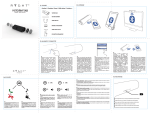
1 Overview
TX
RX
RX
TX
GND
GND
* Transmit data by BLE
* Can communication with most of MCU UART in
3.3v level
* Android/IOS/PC Connected by BLE
4
BLE SPS Module User Manual
Description:
The BLE module is designed with TI CC2540/CC2541 that is a Bluetooth low
energy chip which is compliant Bluetooth 4.0 single-mode. It is mainly used in
low-power sensor networks and short-range wireless communication. The basic
function of WB-BLE-001 is to transmit data between WB-BLE-001 module and
WB-BLE-001 module or WB-BLE-001 module and smart phone.
WB-BLE-001 integrates with the “AT” command set. So the module can set in
master role or slave role, the name of the module can be modified, the baud rate,
advertising interval value and the connection parameters can be modified by users.
Feature:
Small size2.2*1.5 cm
Long communication distance Smart phone to Module:60meters;Module to
Module :100meters(In open environment)
Optimize the BLE stack in depth,Works Power Consumption:60 ~ 800uA;
Master and slave can be switch
A serial port for sending interval <10ms
Respond time from sleep less than 0.4S
Transmit speed 3~5Kb/s
Integrate AT command set
Support Android 4.3 、IOS、PC
No need MFI
WeBee Provide:
PC software for Modify and view the relate parameters
APP Test Software
Professional technical guidance
Support enterprise, individual additional customization
5
BLE SPS Module User Manual
2 Module Package
Figure 2.1 Module Package
3 Factory settings
Item
Module
Module name
Module Baud Rate
Slave (Peripheral) role
"BLE SPS"
115200bps,Data filed 8bit,stop bit
1bit,No odd-even check
6
BLE SPS Module User Manual
4 Data transmit and Command Set
The pin that the module used are as follow:
Pin
VDD
GND
P0_2
P0_3
P0_0
P0_1
P1_0
IO
--RX0
TX0
I(Input)
I(Input)
0(Output)
Use
VDD
GND
The Rx Pin of Module
The Tx pin of Module
Sleep/wake up
Data/Command
Connection status
Comment
P0_4
I(Input)
Store factory setting
Pin
P0_0
P0_1
Sleep
0
X
Data Transmit Mode
1
1
Command Mode
1
0
High Level :Connection
LowLeve :Disconnectio
n
Pull down the pin more
than 2 second
Mode
When the pin P0_0 pull up as high level and at this time the pin P0_1 also pull up as
high level, then the module works in transmit data mode.
When the pin P0_0 pull up as high level and at this time the pin P0_1 pull down as
low level, then the module works in command setting mode.
When both P0_0 and P0_1 are pulled down as low level, then the module works in
sleep mode.
Note:
1. Pin P0_0 can be connected to a pull-up resistor to 3.3V, if the Users don’t need
the sleep mode.
2. Pin P0_1 can be connected to a pull-up resistor to 3.3v, if the Users don’t need
the command setting mode.
3. WeBee can help custom to modify the firmware for the special application.
7
BLE SPS Module User Manual
5 The format of command setting
All the command format is consist of ”FA+type+data length+data+AA”, the head of
the command frame is FA, type is the command type, data length is the length of
user data in this frame, AA is the finish symbol of the command frame.
5.1 Switch to the Slave(Peripheral) role
The default role of module is slave role. As slave role, it can communication with the
smart phone and also the master role module.
The command is: FA 00 00 AA
If executed successful, the module will return “Set Peripheral Role OK\n”
immediately. Otherwise it means it set failed.
5.2 Switch to the Master(Central)role
As the master role, the module only communicates with the slave module.
The command is: FA 01 00 AA
If executed successful, the module will return “Set Central role OK\n” immediately.
Otherwise it means it set failed.
5.3 Modify the baud rate
The module can compatible with a variety of baud rate.
The command to set the baud rate is: FA 02 01 Baudrate AA
Baudrate
Baud Rate
Command
00
9600bps
FA 02 01 00 AA
01
19200bps
FA 02 01 01 AA
02
38400bps
FA 02 01 02 AA
03
57600bps
FA 02 01 03 AA
04
115200bps
FA 02 01 04 AA
If executed successful, the module will return “Set the BaudRate OK\n” immediately.
Otherwise it means it set failed.
5.4 Set the address of the target module
When the module is in master role, it is need to set the master module connect
8
BLE SPS Module User Manual
which slave module.
The command is: FA 03 06 XX XX XX XX XX XX AA;
“XX XX XX XX XX XX” This 6 bytes is the target slave module address.
If executed successful, the module will return "Set target address ok\n" immediately.
Otherwise it means it set failed.
Note: When the target slave module address is set as “00 00 00 00 00 00”, it means
the master will connect the target slave module which the master first scanned.
The factory setting is the “00 00 00 00 00 00”.
5.5 Set the advertising interval value
When the module is slave role, it may need to set the advertising interval value.
The command is: FA 04 length interval AA
For example if want to set advertising interval value in 500ms, so the 500/0.625=800.
Then turns the 800 into Hexadecimal: 800(d) = 320(h)
Then 320 is the 03 and 20, so the Command is FA 04 02 03 20 AA.
If executed successful, the module will return "Set Advertising interval OK\n"
immediately. Otherwise it means it set failed.
5.6 Set connection parameters
The connection parameters influence the data transmit speed and the power
consumption.
The command is: FA 05 08 conn_min conn_max latency timeout AA
There are 4 variables, every variable is 2 bytes.
For example if the conn_min set as 6,
conn_max set as 150
latency set as 0
timeout set as 300
Then the final command is : FA 05 08 00 06 00 96 00 00 01 2C AA
If executed successful, the module will return "Set Connection Interval OK\n"
immediately. Otherwise it means it set failed.
Note: The small of the connection interval, the speed is faster and the power
consumption is higher.
conn_min and conn_max (In 1.25 ms unit, range: 7.5 ms to 4 s (0x0006 - 0x0C80))
Latency (Range 0-499)
Timeout (In 10ms unit,Range: 100ms to 32 seconds (0x000a - 0x0c80).)
9
BLE SPS Module User Manual
5.7 Set the module name
When the module in slave role, use the following command can set the advertising
name.
Command: FA 06 name_length name AA
For example the name of module is set in ”123”,then the command is FA 06 03 31 32
33 AA
If executed successful, the module will return "Set Name OK\n"immediately.
Otherwise it means it set failed.
Note: The length of module name less than 21 bytes.
6 View Parameters command
WB-BLE-001 module provides the interface to view the module parameters. The
current role of the module, baud rate of the module, advertising interval value of
module, connection interval value of module and the name of the module can be
viewed.
The view command format is: ”FB+type+00+AA”
6.1 View Current role of module
View the current role of the module, the command is following:
FB 00 00 AA
If executed successful, the UART of the module will return as follow:
When module is Peripheral role: print “ Peripheral Role”
When module is Central role: print “Central Role”.
6.2 View the Baud Rate of Module
View the Baud Rate of the module, the follow command is provided:
FB 01 00 AA
If executed successful, the UART of module will print: "Baudrate is: 9600", that meas
the baud rate of module is 9600bps.
10
BLE SPS Module User Manual
6.3 View the target module BT address
When the module is in central role, it can be view the BT address of target module
that the central module will connect. The command is as follow:
FB 02 00 AA
If execute successful, the UART of module will print:Target Address:xxxxxxxxxxxx,
xxxxxxxxxxxx is the target peripheral BT address.
6.4 View the BT address of the module
Every module has itself BT address, the following command can get the local module
BT address:
FB 03 00 AA
If execute successful, the UART of module will print: Local Address:xxxxxxxxxxxx
6.5 View the name of module
The name of module can be got by smart phone when the module is in peripheral
role. Also can be got by UART. The following command can get:
FB 04 00 AA
the UART of module will print the name of the modle.
6.6 View the advertising interval value of module
Using the following command can get the advertising interval value of module:
FB 05 00 AA,
If execute successful, the UART of module will print the advertising interval value.
6.7 View the connection parameters.
The following command can get the connection parameters:
FB 06 00 AA
If execute successful, the UART of module will print the connection parameters.
11
BLE SPS Module User Manual
7 Program Example
The external MCU sends the data to the module, the external MCU firstly must pull
up the P0_0 pin the module in order in wake up the module. When finish sending
data, the external MCU must bt pull down the P0_0 pin of the module.
Void sendDataViaBt(unint8 *buf,uint8 len)
{
P0_0=1 //Wake uk
Delay_10us();
Uart_send(buf,len);
Delay_1ms();
P0_0=0;
//Make the module into sleep for saving power
}
8 Test Tool
8.1 PC software test tool
1. After installed the PC BLE software, the following picture will show.
12
BLE SPS Module User Manual
2. Click the “Serial Configure” and input the baud rate value
13
BLE SPS Module User Manual
3. Click the “OK” to open the UART of PC.
4. Here provide “View the module role” for example. Other test, the users can do by
yourself.
From the Part4, If send the command to the module must Pull Down the P1_0
pin. If uses WeBee Board, Pressed the S2 Key and click the “Module role” in the
“View Command set”.
14
BLE SPS Module User Manual
It shows the current role is “Central”
Note: Users can do this by “UART Assistant” software without WeBee software.
15
BLE SPS Module User Manual
8.1 Test the Data Passthrough Between module and module.
Power on the module, When the LED1 is on that means this 2 modules is connected.
Then open the “UART Assistant” software and set the UART number and baud rate.
Then this to module can transmit data to each other.
16
BLE SPS Module User Manual
8.2 Test Data Passthrough in Smartphone
The smartphone can only communication with the Peripheral role module.
8.2.1 Use “LightBlue” APP for Testing.
1. Download the ”LightBlue” app in apple app store and install it.
17
BLE SPS Module User Manual
2. Module connects to the PC via USB and Power on it. At this time, the lightblue
will found the “BLE SPS” the listed it. As the following shows.
18
BLE SPS Module User Manual
3. Click the “BLE SPS”, the smart phone will connect to the module and the LED1 of
the board will be on. The following picture means the connection is built.
19
BLE SPS Module User Manual
4. Click “ 0xFEE0”, it will show “0xFEE1” and click “0xFEE1”,it will show the following
picture:
20
BLE SPS Module User Manual
5. Click “Write” will send the data from smartphone to module.
21
BLE SPS Module User Manual
22
BLE SPS Module User Manual
6. The module gets the data from the smartphone will show in “UART Assistant”
software.
7. Now make the module sends data to smartphone:
Click “start notify” in the following picture.
23
BLE SPS Module User Manual
8. PC software Sends “123” to Module via UART
9. The smartphone will get the data “123” from the module. It shows as following:
24
BLE SPS Module User Manual
8.2.2 Use the APP testing that WeBee provide(ios7.0 above)
10. Download the ”BLE SPS” app in apple app store and install it.
25
BLE SPS Module User Manual
26
BLE SPS Module User Manual
1. Connect the module to PC via USB. Click “Scan Ble Device”
b
2. The app will list the device, when it has scan the BLE Module, Device name is:
“BLE SPS”, Choose “BLE SPS” to be connected.
27
BLE SPS Module User Manual
3. After the connection is built, they can transmit data to each other.
28