1
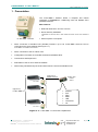
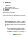
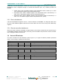
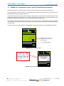
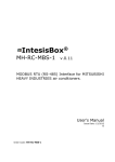
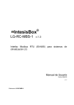
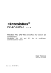
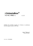
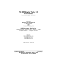
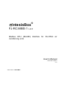
IntesisBox ® FJ-RC-MBS-1 v.2.2 Modbus RTU (EIA485) Interface for FUJITSU air conditioning units. User's Manual Issue Date: 09/2013 r1.6 Order Code: FJ-RC-MBS-1 IntesisBox® FJ-RC-MBS-1 User’s Manual r1.6 eng © Intesis Software S.L. 2013 All Rights Reserved. Information in this document is subject to change without notice. No part of this publication may be reproduced, stored in a retrieval system or transmitted in any form or any means electronic or mechanical, including photocopying and recording for any purpose other than the purchaser’s personal use without the written permission of Intesis Software S.L. Intesis Software S.L. Milà i Fontanals, 1 bis 08700 Igualada Spain TRADEMARKS All trademarks and trade names used in this document are acknowledged to be the copyright of their respective holders. © Intesis Software S.L. - All rights reserved This information is subject to change without notice ® IntesisBox is a registered trademark of Intesis Software SL URL Email tel http://www.intesis.com [email protected] +34 938047134 2 / 17 IntesisBox® FJ-RC-MBS-1 User’s Manual r1.6 eng INDEX 1. Presentation .................................................................................................... 4 2. Connection ...................................................................................................... 5 2.1 Connection of the interface to the AC indoor unit ............................................... 5 2.2 Connection of the interface to Modbus ............................................................. 5 2.3 Power-up ..................................................................................................... 6 3. Modbus Interface Specification ........................................................................... 7 3.1 Modbus physical layer .................................................................................... 7 3.2 Modbus Registers .......................................................................................... 7 3.2.1 3.2.2 Control and status registers ...................................................................... 7 Configuration Registers ............................................................................ 8 3.3 DIP-switch Configuration Interface .................................................................. 9 3.4 Implemented Functions ................................................................................ 11 3.5 Special behaviors ........................................................................................ 11 3.5.1 3.5.2 3.5.3 3.5.4 Window contact .................................................................................... Considerations on FJ-RC-MBS-1 temperature registers ............................... Device disablement ............................................................................... Remote controller disablement ................................................................ 11 11 12 12 3.6 Device LED indicator .................................................................................... 12 3.7 EIA485 bus. Termination resistors and Fail Safe Biasing mechanism .................. 13 4. Specifications................................................................................................. 14 5. AC Unit Types Compatibility ............................................................................. 14 6. Error Codes ................................................................................................... 15 6.1 RAC and VRF J-II / V-II / VR-II series ............................................................ 15 6.2 VRF V / S / J series ...................................................................................... 17 © Intesis Software S.L. - All rights reserved This information is subject to change without notice ® IntesisBox is a registered trademark of Intesis Software SL URL Email tel http://www.intesis.com [email protected] +34 938047134 3 / 17 IntesisBox® FJ-RC-MBS-1 User’s Manual r1.6 eng 1. Presentation The FJ-RC-MBS-1 interface allows a complete and natural integration of FUJITSU air conditioning units into Modbus RTU (EIA485) networks. Main features: Reduced dimensions. 93 x 53 x 58 mm. Quick and easy installation. Mountable on DIN rail, wall, or even inside the indoor unit in some models of AC. FJ-RC-MBS-1 device External power not required. Direct connection to Modbus RTU (EIA485) networks. Up to 63 FJ-RC-MBS-1 devices can be connected in the same network (See Figure 1.1). FJ-RC-MBS-1 is a Modbus slave device. Direct connection to the AC indoor units. Configuration from both on-board DIP-switches and Modbus RTU. Total Control and Supervision. Real states of the AC unit's internal variables. Allows using simultaneously the IR and wired remote controls and Modbus RTU. Modbus RTU EIA485 network Modbus RTU master device FJ-RC-MBS-1 Up to 63 FJ-RC-MBS-1 FJ-RC-MBS-1 SCADA PLC DDC BMS HMI Controller etc FJ-RC-MBS-1 Figure 1.1 FJ-RC-MBS-1 Connection capabilities © Intesis Software S.L. - All rights reserved This information is subject to change without notice ® IntesisBox is a registered trademark of Intesis Software SL URL Email tel http://www.intesis.com [email protected] +34 938047134 4 / 17 IntesisBox® FJ-RC-MBS-1 User’s Manual r1.6 eng 2. Connection 2.1 Connection of the interface to the AC indoor unit The FJ-RC-MBS-1 connects directly to the Fujitsu 3-wire cable bus. Depending on which controllers are available the recommended connection methods are the following (details in Figure 2.1): Wired remote control available. Connect the gateway as Slave in parallel with the wired remote controllers (Wall controller acts as master). Infrared remote control available. Connect the gateway as Master. No remote control available Connect the gateway directly to the 3-wire bus of the indoor unit as Master when there is no FUJITSU remote control. Disconnect power supply from the AC unit and use a 3-wire cable for the connection of FJ-RC-MBS-1, FUJITSU wired remote controller and its corresponding indoor unit. Screw the suitably peeled cable ends in the corresponding terminals of each device, as summarized in Figure 2.1. Maximum connection bus length is 500 meters and has polarity. 2.2 Connection of the interface to Modbus Use the EIA485 connector in the FJ-RC-MBS-1 to connect to the Modbus network. 53 mm Remote Control AC Indoor Unit For wall mount extract the upper and down staples until you hear the "click". BWR AC Unit IntesisBox® R W FJ-RC-MBS-1 B EIA485 A+ B- 93 mm GND (3) B Data (2) W Power (1) R Internal electronic control board MODBUS RTU EIA485 Bus Max. 500 m 53 mm AC Indoor Unit BWR AC Unit IntesisBox® FJ-RC-MBS-1 EIA485 A+ B- GND (3) B Data (2) W Power (1) R Internal electronic control board 93 mm MODBUS RTU EIA485 Bus Max. 500 m Figure 2.1 FJ-RC-MBS-1 connection diagram © Intesis Software S.L. - All rights reserved This information is subject to change without notice ® IntesisBox is a registered trademark of Intesis Software SL URL Email tel http://www.intesis.com [email protected] +34 938047134 5 / 17 IntesisBox® FJ-RC-MBS-1 2.3 User’s Manual r1.6 eng Power-up After the FJ-RC-MBS-1 is properly connected, AC unit’s main power can be connected again. Then, it will start an initialization process which can take around 2 minutes before the normal operation starts. While the initialization is ongoing, some Modbus registers will indicate an undetermined value (see section 3.2). Once the normal operation starts, they will acquire its corresponding value. It is important to bear in mind that changes made during the initialization process will not have effect until it finishes. © Intesis Software S.L. - All rights reserved This information is subject to change without notice ® IntesisBox is a registered trademark of Intesis Software SL URL Email tel http://www.intesis.com [email protected] +34 938047134 6 / 17 IntesisBox® FJ-RC-MBS-1 User’s Manual r1.6 eng 3. Modbus Interface Specification 3.1 Modbus physical layer FJ-RC-MBS-1 implements a Modbus RTU (slave) interface, to be connected to an EIA485 line. It performs 8N2 (8N1-compatible) communication (8 data bits, no parity and 2 stop bit) with several available baudrates (2400 bps, 4800 bps, 9600 bps -default- and 19200 bps). 3.2 Modbus Registers All registers are of type “16-bit unsigned register”, in standard Modbus’ big endian notation. The registers are accessible as “Holding registers” or “Inputs registers”. 3.2.1 Control and status registers Register Addr (protocol address) Register Addr (PLC address) R/W 0 1 R/W Description AC unit On/Off 0: Off 1: On AC unit Mode 1 2 R/W 0: Auto 1: Heat 2: Dry 3: Fan 4: Cool AC unit Fan Speed 2 3 R/W Val. 0 1 2 3 4 1 Num. of Fan Speeds 3 2 Undetermined Low Low Low Mid Mid High High High Powerful 4 (default) AC unit Vane Position 3 4 R/W 5 R/W 0: Undetermined 1…4: Pos. 1 … Pos. 4 10: Swing 6 R 7 R/W 4 0: Closed 1: Open Device Disablement 7 8 R/W 3 16..30 (ºC) (0 = undetermined) 61..86 (ºF) (0 = undetermined) 0x8000 There is no temperature sent from the Remote controller. Window Contact 6 2,3 16..30 (ºC) (0 = undetermined) 61..86 (ºF) (0 = undetermined) Return Path Temperature 5 4 0: FJ-RC-MBS-1 enabled 1: FJ-RC-MBS-1 disabled Remote Controller Disablement 8 1 2 3 4 9 R/W High - 1 AC unit Temperature Setpoint 4 1 4 0: Remote Controller enabled 1: Remote Controller disabled Configurable according to Table 3.1 Magnitude for this register can be adjusted through DIP switch (Check Table 3.4) More information in section 3.5.2 See explanation of this functionality in section 3.5 © Intesis Software S.L. - All rights reserved This information is subject to change without notice ® IntesisBox is a registered trademark of Intesis Software SL URL Email tel http://www.intesis.com [email protected] +34 938047134 7 / 17 IntesisBox® FJ-RC-MBS-1 User’s Manual r1.6 eng Register Addr (protocol address) Register Addr (PLC address) R/W 9 10 R/W 10 11 R 11 12 R 22 23 R/W 23 24 R 24 25 R 25 26 R 26 27 R/W Description AC unit Operation Time 5 0..65535 (hours). Counts the time the AC unit is in “On” state. AC unit Alarm Status 0: No alarm condition 1: Alarm condition Error Code -1 Communication error. Other look in section 0 External temperature sensor Ranges are manufacturer specific Can be ºC or ºF, x1 or x10 0x8000 (-32768d) means "no input sensor" AC real setpoint Ranges are manufacturer specific Can be ºC or ºF, x1 or x10 Current AC MAX setpoint Ranges are manufacturer specific Can be ºC or ºF, x1 or x10 Current AC min setpoint 27 28 34 35 R/W W Ranges are manufacturer specific Can be ºC or ºF, x1 or x10 Vane L/R position 0 - AUTO; 1-POS1 … 9 - POS9; 10-SWING U/D Vane Pulse 1 - Pulse L/R Vane Pulse 1: Pulse Economy 64 65 R/W 65 66 R Register Address (PLC address) R/W 0: Not active 1: Active Input reference temperature Can be ºC or ºF, x1 or x10 3.2.2 Configuration Registers Register Address (protocol address) Description “Open Window” switch-off timeout 13 14 R/W 14 15 R 15 16 R 0..30 (minutes) Factory setting: 30 (minutes) Modbus RTU baudrate (bps) 6, 7 7 2400, 4800, 9600, 19200 Device's Modbus slave address 1..63 Max number of fan speeds 5 6 7 21 22 R 48 49 R 49 50 R 50 51 R 1..4: must be configured according to the number of fan speeds supported by the AC unit Switch value Device Identification FJ-RC-MBS-1: 0x0F00 Software version This value is stored in non-volatile memory. Once window contact is open, a count-down to switch off the AC Unit will start from this configured value Configurable through S3 (See Table 3.3) © Intesis Software S.L. - All rights reserved This information is subject to change without notice ® IntesisBox is a registered trademark of Intesis Software SL URL Email tel http://www.intesis.com [email protected] +34 938047134 8 / 17 IntesisBox® FJ-RC-MBS-1 3.3 User’s Manual r1.6 eng DIP-switch Configuration Interface In this section, values of the configuration switches and their meaning are specified: L1 L2 S1 ON 1 2 3 4 B W R AC Unit IntesisBox® FJ-RC-MBS-1 EIA485 A+ B- ON 1 2 3 4 5 6 7 8 ON 1 2 3 4 S3 S4 Figure 3.1 FJ-RC-MBS-1 S1 – AC unit configuration: Master/Slave, Slave of Operating Mode and Machine Type Binary value b3…b0 Decimal value Switches 1 2 3 4 0xxx 0 x x x 1xxx 1 x x x x0xx 0 x x x KEEP SWITCH IN THIS POSISIONT (default value) x1xx 1 x x x DO NOT TURN SWITCH INTO THIS POSITION (not applicable). xx0x 0 x x x Error Type_B (default value) Xx1x 1 x x x Error Type_A xxx0 0 x x x KEEP SWITCH IN THIS POSISIONT (default value) xxx1 1 x x x DO NOT TURN SWITCH INTO THIS POSITION (not applicable). Description Slave (default value) – A FUJITSU Controller must be present in the bus, configured as Master. Master in the bus – FUJITSU Controller not needed in the bus. If existing, it must be configured as Slave. Table 3.1 S1 Switch configuration © Intesis Software S.L. - All rights reserved This information is subject to change without notice ® IntesisBox is a registered trademark of Intesis Software SL URL Email tel http://www.intesis.com [email protected] +34 938047134 9 / 17 IntesisBox® FJ-RC-MBS-1 User’s Manual r1.6 eng S3 – Modbus protocol: Slave address and baudrate Add Switches 1 2 3 4 5 6 7 8 Add Switches 1 2 3 4 5 6 7 8 Add Switches 1 2 3 4 5 6 7 8 Add Switches 1 2 3 4 5 6 7 8 0 x x 16 x x 32 x x 48 x x 1* x x 17 x x 33 x x 49 x x 2 x x 18 x x 34 x x 50 x x 3 x x 19 x x 35 x x 51 x x 4 x x 20 x x 36 x x 52 x x 5 x x 21 x x 37 x x 53 x x 6 x x 22 x x 38 x x 54 x x 7 x x 23 x x 39 x x 55 x x 8 x x 24 x x 40 x x 56 x x 9 x x 25 x x 41 x x 57 x x 10 x x 26 x x 42 x x 58 x x 11 x x 27 x x 43 x x 59 x x 12 x x 28 x x 44 x x 60 x x 13 x x 29 x x 45 x x 61 x x 14 x x 30 x x 46 x x 62 x x 15 x x 31 x x 47 x x 63 x x Table 3.2 S3 Modbus Slave address Binary value b0…b7 Decimal value Switches 1 2 3 4 5 6 7 8 Description xxxxxx00 0 x x x x x x 2400bps xxxxxx10 1 x x x x x x 4800bps xxxxxx01 2 x x x x x x 9600bps (- default value) xxxxxx11 3 x x x x x x 19200bps Table 3.3 S3 Modbus baudrate S4 – Temperature and termination: Degrees/Decidegrees (x10), temperature magnitude (ºC/ºF), number of fan speeds and EIA485 termination resistor. Binary value b0…b3 Decimal value Switches 1 2 3 4 Description 0xxx 0 x x x Temperature values in Modbus register are represented in degrees (x1) (default value) 1xxx 1 x x x Temperature values in Modbus register are represented in decidegrees (x10) x0xx 0 x x x Temperature values in Modbus register are represented in Celsius degrees (default value) x1xx 1 x x x Temperature values in Modbus register are represented in Fahrenheit degrees xx0x 0 x x x KEEP SWITCH IN THIS POSISIONT (default value) xx1x 1 x x x DO NOT TURN SWITH INTO THIS POSITION (not applicable). xxx0 0 x x x EIA485 bus without termination resistor (default value) xxx1 1 x x x Internal termination resistor of 120Ω connected to EIA485 bus** Table 3.4 S4 Temperature and termination configuration * Default value ** The termination resistor must only be activated in the interfaces connected at both ends of the bus, not in the rest. The EIA485 bus can be biased through internal jumpers JP2 and JP3. See section 3.7. © Intesis Software S.L. - All rights reserved This information is subject to change without notice ® IntesisBox is a registered trademark of Intesis Software SL URL Email tel http://www.intesis.com [email protected] +34 938047134 10 / 17 IntesisBox® FJ-RC-MBS-1 3.4 User’s Manual r1.6 eng Implemented Functions FJ-RC-MBS-1 implements the following standard Modbus functions: 3: Read Holding Registers 4: Read Input Registers 6: Write Single Register 16: Write Multiple Registers (Although this function is allowed, the interface does not allow write operations of more than 1 register with the same request, this means that length field should always be 1 when using this function for writes) The maximum number of registers that can be read in a single request is 100. 3.5 Special behaviors 3.5.1 Window contact The FJ-RC-MBS-1 has the functionality of automatically control the turning off of the AC indoor unit depending on the state of the window contact register. The AC indoor unit will be turned OFF if the window contact register indicates “window opened” for a certain period of time (default value: 30 minutes). If the AC unit is turned on through either the remote controller or the On/Off register and the window contact is still indicating “window opened”, it will restart the countdown of the 30 minutes and after that it will turn OFF the AC unit again. If the window contact register is indicating “window closed”, this functionality will have no effect to the normal operation. 3.5.2 Considerations on FJ-RC-MBS-1 temperature registers FJ-RC-MBS-1 implements two registers containing temperature values: AC unit Temperature Setpoint (R/W) (register 5 – in PLC addressing): This is the adjustable temperature setpoint meant to be required by the user. This register can be read (Modbus function 3 or 4) or written (modbus functions 5 or 16). A remote controller connected to the 3-wire bus of the Fujitsu indoor unit will report the same temperature setpoint value as this register. AC unit external reference temperature (R/W) (register 23 – in PLC addressing): This register allows providing an external temperature reference from Modbus side. If an external temperature is provided through this register, indoor unit will use it as reference for its temperature control loop. o o o o This register will have no effect in those Fujitsu RAC / domestic line splits AirConditioning units – this is, those models requiring an additional communication accessory enabling communication with FJ-RC-MBS-1. For this temperature to take effect it is required that the Fujitsu AC indoor unit is configured in such a way that it uses the “thermostat sensor in the remote controller” (this is, FJ-RC-MBS-1 will act as thermostat sensor providing a temperature sensor reading). This configuration is done via a Fujitsu remote controller connected to the indoor unit (Function number “42” – setting value “1” / operation of Thermosensor button) and must be done by Fujitsu authorized installers at the time of the installation of the AC. Register value after FJ-RC-MBS-1 startup is -32768, which means that no temperature reference is provided to the AC indoor unit. In that case, AC indoor unit will use its own return path temperature sensor as reference for its control loop. © Intesis Software S.L. - All rights reserved This information is subject to change without notice ® IntesisBox is a registered trademark of Intesis Software SL URL Email tel http://www.intesis.com [email protected] +34 938047134 11 / 17 IntesisBox® FJ-RC-MBS-1 User’s Manual r1.6 eng Additionally, note that temperature values from all these three registers are expressed according to the temperature format configured through its onboard DIP-Switches (See 3.3). Following formats are possible: Celsius value: Value in Modbus register is the temperature value in Celsius (i.e. a value “22” in the Modbus register must be interpreted as 22ºC) Decicelsius value: Value in Modbus register is the temperature value in decicelsius (i.e. a value “220” in the Modbus register must be interpreted as 22.0ºC) Fahrenheit value: Value in Modbus register is the temperature value in Fahrenheit (i.e. a value “72” in the Modbus register must be interpreted as 72ºF (~22ºC). 3.5.3 Device disablement If the device disablement register is set to 1, it will not allow the FJ-RC-MBS-1 to change the state of the AC unit. All the Modbus registers will show the current state of the AC unit as if they were “Read Only registers”. 3.5.4 Remote controller disablement When the remote controller is disabled, changes made by the remote controller will be corrected by the FJ-RC-MBS-1 setting the previous value. In this way, the FJ-RC-MBS-1 will prevent the remote controller from changing the state of the AC unit. 3.6 Device LED indicator The device includes two LED indicators (check Figure 3.1) to signal its different possible operational states. Their meaning is explained in this section: L1 (green) Operation Blinking Flashing ON 500 ms 100 ms OFF 500 ms 1900 ms L2 (red) Operation Pulse ON 3 sec OFF -- ON 5 sec 500 ms OFF -500 ms L1 (green) & L2 (red) Operation Pulse Alternate blinking © Intesis Software S.L. - All rights reserved This information is subject to change without notice ® IntesisBox is a registered trademark of Intesis Software SL Meaning Error Normal operation (configured and working) Meaning Undervoltage Meaning Device start-up Flash checksum not OK URL Email tel http://www.intesis.com [email protected] +34 938047134 12 / 17 IntesisBox® FJ-RC-MBS-1 3.7 User’s Manual r1.6 eng EIA485 bus. Termination resistors and Fail Safe Biasing mechanism EIA485 bus requires a 120Ω terminator resistor at each end of the bus to avoid signal reflections. The FJ-RC-MBS-1 device includes an on-board terminator resistor of 120Ω that can be connected to the EIA485 bus by using DIP-switch (Table 3.4). A fail safe biasing circuit has also been included in the board of FJ-RC-MBS-1, it can be connected to the EIA485 bus by placing internal JP1 and 1 jumpers (see details in Figure 3.2). This fail safe biasing of the EIA485 bus must only be supplied by one of the devices connected to the bus. Some Modbus RTU EIA485 master devices can provide also internal 120Ω terminator resistor and/or fail safe biasing (consult the technical documentation of the master device connected to the EIA485 network in every case). Location of jumper and DIP-switches for EIA485 bus Termination resistor or Fail Safe Biasing selection: ON 1 2 3 4 JP1 1 Jumper placed Fail safe biasing circuit connected to the EIA485 bus JP2: ON (jumper placed) ON 1 2 3 4 5 6 7 8 ON 1 2 3 4 Figure 3.2 Fail Safe jumper ON 1 2 3 4 To access to internal jumpers JP1 and 1, extract the top cover of the interface inserting a small screw-driver or clip in the holes located at both sides of the cover. B W R AC Unit IntesisBox® FJ-RC-MBS-1 EIA485 A+ BON 1 2 3 4 5 6 7 8 ON 1 2 3 4 Figure 3.3 Accessing the jumper © Intesis Software S.L. - All rights reserved This information is subject to change without notice ® IntesisBox is a registered trademark of Intesis Software SL URL Email tel http://www.intesis.com [email protected] +34 938047134 13 / 17 IntesisBox® FJ-RC-MBS-1 User’s Manual r1.6 eng 4. Specifications Dimensions: Weight: Consumption Current: Operating Temperature: Stock Temperature: Operating Humidity: Stock Humidity: Isolation voltage: Isolation resistance: Modbus Media: 93 x 53 x 58 mm 85 g 80 mA 0 . . . 40ºC -40 . . . 85ºC <95% RH, non-condensing <95% RH, non-condensing 1000 VDC 1000 MΩ Compatible with Modbus RTU - EIA485 networks AC Unit connection LED Indicator DIP Switches DIP Switches 58 mm EIA485 Port 53 mm 93 mm Figure 4.1 FJ-RC-MBS-1 external sketch 5. AC Unit Types Compatibility A list of FUJITSU indoor unit model references compatible with FJ-RC-MBS-1 and their available features can be found in: http://www.intesis.com/pdf/IntesisBox_FJ-RC-xxx-1_AC_Compatibility.pdf © Intesis Software S.L. - All rights reserved This information is subject to change without notice ® IntesisBox is a registered trademark of Intesis Software SL URL Email tel http://www.intesis.com [email protected] +34 938047134 14 / 17 IntesisBox® FJ-RC-MBS-1 User’s Manual r1.6 eng 6. Error Codes In order to get the right values regarding AC error codes, remember that you have to select the proper switch configuration. Find below a summary table of the different AC systems and the switch configuration for each of them to be selected. AC System Type Switch configuration (S1) Error section RAC non inverter models 6.1 RAC inverter models (x x x) 6.2 VRF V / S / J (x x x) RAC inverter model G* series 6.1 VRF J-II / V-II / VR-II (x x x) * G series stands for units that include a ‘G’ just before the power number in its reference. E.g.: ASYG09LTCA NOTE: Devices with Software Version (register 51 in PLC-addresses) 2.1 and below connected to RAC inverter model G series or VRF J-II / V-II / VR-II series will need to add 100 to the error code prompted. That is, if error prompted is 17, the corresponding error in the list below might be 17+100 = 117. 6.1 RAC and VRF J-II / V-II / VR-II series Error in Modbus 0 1 2 3 4 5 6 7 8 9 10 11 12 13 14 15 17 18 19 20 21 22 23 24 Error in Remote Controller 00 01 02 03 04 05 06 07 08 09 0A 0b 0C 0d 0E 0F 11 12 13 14 15 16 17 18 25 19 26 27 28 29 30 31 32 33 34 36 37 38 39 40 41 42 1A 1b 1C 1d 1E 1F 20 21 22 24 25 26 27 28 29 2A Error Description © Intesis Software S.L. - All rights reserved This information is subject to change without notice ® AC System Type Wired remote controller error Indoor signal error Indoor room temperature sensor error Indoor room temperature sensor error Indoor heat exchanger temperature sensor (middle) error Indoor heat exchanger temperature sensor (middle) error Outdoor heat exchanger temperature sensor (outlet) error Outdoor heat exchanger temperature sensor (outlet) error Power voltage error Float switch operated Outdoor temperature sensor error Outdoor temperature sensor error Outdoor discharge pipe temperature sensor error Outdoor discharge pipe temperature sensor error Heat sink thermistor (Inverter) error Discharge temperature error Indoor unit EEPROM error Indoor fan error Indoor signal error Outdoor EEPROM error Compressor temperature sensor error Pressure switch abnormal, Pressure sensor error IPM protection CT error Active filter error INV voltage protection Compressor location error Outdoor fan error Outdoor unit computer communication error 2-way valve temperature sensor error 3-way valve temperature sensor error Connected indoor unit error Indoor MANUAL AUTO switch error reverse VDD permanent stop protection VDD permanent stop protection Excessive high pressure protection on cooling P.F.C. circuit error Indoor signal error Indoor signal error Indoor heat exchanger temperature sensor (inlet) error Outdoor heat exchanger temperature sensor (middle) error Power supply frequency detection error IntesisBox is a registered trademark of Intesis Software SL URL Email tel RAC Inverter and Non Inverter http://www.intesis.com [email protected] +34 938047134 15 / 17 IntesisBox® FJ-RC-MBS-1 43 44 45 2b 2C 2d 46 2E 47 48 49 50 51 52 53 54 55 56 117 118 119 120 121 122 123 133 134 135 136 137 138 139 140 141 149 150 151 152 153 154 155 156 157 158 165 166 167 168 169 170 171 172 173 181 182 183 184 185 186 187 188 189 195 197 198 199 200 201 202 203 204 205 206 213 214 215 216 217 218 219 220 229 230 231 232 233 2F 30 31 32 33 34 35 36 37 38 11 12 13 14 15 16 17 21 22 23 24 25 26 27 28 29 31 32 33 34 35 36 37 38 39 3A 41 42 43 44 45 46 47 48 49 51 52 53 54 55 56 57 58 59 5U 61 62 63 64 65 66 67 68 69 6A 71 72 73 74 75 76 77 78 81 82 83 84 85 Compressor temperature error 4-way valve error Heat sink thermistor P.F.C. error Indoor unit damper error Inverter error Low pressure error Refrigerant circuit address set-up error Master unit, Slave unit set-up error Connected the indoor number set-up error P.F.C. printed circuit board error Indoor fan 2 error Control box thermistor error Indoor unit CT error Indoor fan motor 1 driving circuit error Indoor fan motor 2 driving circuit error Serial communication error between indoor/outdoor units Remote controller communication error Communication error between outdoor units Network communication error Scan error Peripheral unit communication error Electricity charge apportionment error Indoor unit initial setting error Indoor unit capacity abnormal Incompatible series connection error Connection unit number error Connection pipe length error Indoor unit address setting error Master/slave unit setting error Other setting error Connection unit number error in wired remote controller system Indoor unit power supply abnormal Indoor unit main PCB error Indoor unit display PCB error Power relay error Indoor unit manual auto switch error Heater relay error Indoor unit transmission PCB error Network convertor PCB error Indoor unit power supply circuit error Indoor unit communication circuit (wired remote controller) error Indoor unit room temp. thermistor error Indoor unit heat ex. temp. thermistor error Humidity sensor error Light sensor error Gas sensor error Float sensor error Water temperature sensor error Warm water flow rate sensor error Heater sensor error Indoor unit fan motor 1 error Indoor unit coil (expansion valve) error Indoor unit water drain abnormal Air cleaning function error Filter cleaning function error Water circulation pump error Indoor unit damper error Indoor unit intake grille position error Indoor unit fan motor 2 error Indoor unit miscellaneous error Outdoor unit power supply abnormal Outdoor unit main PCB error Outdoor unit inverter PCB error Outdoor unit active filter/PFC circuit error Outdoor unit IPM error Convertor distinction error Outdoor unit power short interruption error (protective operation) Outdoor unit magnetic relay error Outdoor unit transmission PCB error Outdoor unit display PCB error Outdoor unit discharge temp. thermistor error Outdoor unit compressor temp. thermistor error Outdoor unit heat ex. temp. thermistor error Outside air temp. thermistor error Outdoor unit suction gas temp. thermistor error Outdoor unit operating valve thermistor error Outdoor unit heat sink temp. thermistor error Expansion valve temperature sensor error Receiver liquid level detection sensor error Outdoor unit sub-cool heat ex. gas temp. thermistor error Outdoor unit liquid pipe temp. thermistor error Outdoor unit current sensor error Fan motor current sensor error © Intesis Software S.L. - All rights reserved This information is subject to change without notice ® User’s Manual r1.6 eng IntesisBox is a registered trademark of Intesis Software SL URL Email tel RAC Inverter models G series VRF J-II / V-II / VR-II Series http://www.intesis.com [email protected] +34 938047134 16 / 17 IntesisBox® FJ-RC-MBS-1 234 235 245 246 247 248 249 250 251 252 253 254 259 261 262 263 264 265 266 267 268 269 270 271 272 273 277 278 279 280 281 282 283 284 285 286 287 288 289 293 294 295 296 309 310 311 312 313 6.2 86 87 91 92 93 94 95 96 97 98 99 9A 9U A1 A2 A3 A4 A5 A6 A7 A8 A9 AA AC AF AJ C1 C2 C3 C4 C5 C6 C7 C8 C9 CA CC CF CJ F1 F2 F3 F4 J1 J2 J3 J4 J5 User’s Manual r1.6 eng Outdoor unit pressure sensor error Oil sensor error Outdoor unit compressor 1 error Outdoor unit compressor 2 error Outdoor unit compressor start up error Outdoor unit trip detection Outdoor unit compressor motor control error Open loop error(Field-weakening relevant) Outdoor unit fan motor 1 error Outdoor unit fan motor 2 error Outdoor unit 4-way valve error Outdoor unit coil (expansion valve) error Outdoor unit miscellaneous error Outdoor unit discharge temperature 1 error Outdoor unit discharge temperature 2 error Outdoor unit compressor temperature error Outdoor unit pressure error 1 Outdoor unit pressure error 2 Outdoor unit heat exchanger temperature error Suction temperature abnormal Poor refrigerant circulation Current overload error Outdoor unit special operation error Ambient temperature error Out of the possible operation range Freeze protection operated Peripheral unit main PCB error Peripheral unit transmission PCB error Peripheral unit PCB 1 error PCB 2 error PCB 3 error PCB 4 error PCB 5 error Peripheral unit input device error Display device error EEPROM error Peripheral unit sensor error Peripheral unit external connector error (USB memory) Other parts error System tool software error System tool adaptor error System tool interface error System tool environment error RB unit error Branch boxes error Total heat exchanging, ventilation unit error Domestic hot water unit error Zone control interface error RAC Inverter models G series VRF J-II / V-II / VR-II Series VRF V / S / J series Error in Modbus 0 2 4 6 7 9 10 11 12 13 17 18 19 Error in Remote Controller 00 02 04 06 07 09 0A 0b 0C 0d 11 12 13 20 18 31 32 33 34 1F 20 21 32 Error Description No Error Model information Error Power frequency Error EEPROM access Error EEPROM deletion Error Room sensor Error Heat Ex. Middle Sensor Error Heat Ex. Inlet sensor Error Heat Ex. Outlet sensor Error Blower temperature thermistor Error Drain Error Room temperature Error Indoor fan motor Error Standard wired remote Error Standard wired token Error Network communication Error Node setting error Communication Error between Main PCB & Transmission PCB Outdoor unit Error VRF V/S/J series In case you detect an error code not listed in any of the different tables above, please contact your nearest FUJITSU technical support service. © Intesis Software S.L. - All rights reserved This information is subject to change without notice ® IntesisBox is a registered trademark of Intesis Software SL URL Email tel http://www.intesis.com [email protected] +34 938047134 17 / 17