1
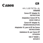
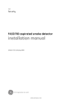
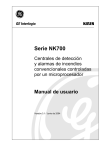
GE
Security
FHSD Monitor / Web Server
user manual
version 1-0 / november 2004
http://www.geindustrial.com/ge-interlogix/emea
© 2004 GE Interlogix B.V.. All rights reserved. GE Interlogix B.V. grants the right to reprint this manual for internal use only. GE
Interlogix B.V. reserves the right to change information without notice.
CONTENTS
1
FHSD Monitor......................................................................................................................................... 4
1.1 Installation and setup .................................................................................................................... 4
1.1.1
Connecting to a PC........................................................................................................ 4
1.1.2
Software installation....................................................................................................... 4
1.1.3
Software setup............................................................................................................... 4
1.2 User guide ..................................................................................................................................... 5
1.2.1
FHSD display panel emulator........................................................................................ 5
1.2.2
FHSD configuration utility .............................................................................................. 6
1.2.3
Engineering and maintenance menus ........................................................................... 8
1.2.4
Data logger .................................................................................................................... 8
1.2.5
Logging extraction application ..................................................................................... 10
1.2.6
Flow diagnostic log ...................................................................................................... 11
2
FHSD Web Server ................................................................................................................................ 12
2.1 FHSD Web Server overview ....................................................................................................... 12
2.2 IP address and IP mask values .................................................................................................. 12
2.3 Access levels and codes............................................................................................................. 12
2.4 FHSD Web Server pages............................................................................................................ 12
2.5 Technical support........................................................................................................................ 14
FHSD Monitor / Web Server User Manual
3
1 FHSD MONITOR
The FHSD Monitor software provides a convenient method for calibration and monitoring
of FHSD700 series panels.
The FHSD720 Pico can only be calibrated using the FHSD Monitor software as the panel
does not include a control interface. Use of FHSD Monitor is optional for all other panels.
1.1 Installation and setup
1.1.1
Connecting to a PC
The FHSD700 panel must be connected to the PC using an RS232 cable. The cable
connects the RS232 connector on the FHSD700 panel I/O PCB i606 to one of the PC
serial communications (COM) ports (usually 1 or 2).
Write down the COM port address used as this will be required later.
1.1.2
Software installation
Installation from CD:
1. Insert the CD into your computer’s CD-ROM drive.
2. The installation program will start automatically. If it doesn’t, choose Start > Run.
Click Browse and choose the file Setup.exe on the CD. Click OK in the Run dialog
box.
3. Follow the onscreen instructions to complete the installation.
Installation from downloaded installer file:
Double-click the downloaded installer file and follow the onscreen instructions.
1.1.3
Software setup
When first run, the program will ask for the COM port address of the PC being used and
the Modbus. Enter the COM port address used and the Modbus address (usually 1).
The main screen of the program will now be visible (see Figure 1 Main screen). The top
of the screen displays information about your FHSD700 system. This includes the
FHSD700 model, whether it is web enabled and the version being used.
4
FHSD Monitor / Web Server User Manual
Figure 1: Main screen
1.2 User guide
The main program screen is blank except for five menu buttons in the top left corner.
These are used to access the various software utilities.
1.2.1
FHSD display panel emulator
Figure 2: Display panel emulator
This launches the FHSD display panel emulator and is used to enter setup and
configuration data in the same was that it would be performed on the panel.
FHSD Monitor / Web Server User Manual
5
See the FHSD700 series installation and user manual for a detailed
explanation of the control panel and menu options.
The other software functions allow panel setup and calibration using forms and tables
and may be more suitable for some users. This method is more detailed and some
variables (such as the IP address) can be entered more easily than via the display panel.
1.2.2
FHSD configuration utility
Figure 3: Configuration utility
All values must be entered with a decimal point even if they are displayed
with a comma.
1. Main list
See the FHSD700 series installation and user manual for a full description of the items
included in this list.
2. Sector list
See the FHSD700 series installation and user manual for a full description of the items
included in this list.
To change the night settings the display panel emulator must be used.
6
FHSD Monitor / Web Server User Manual
3. Setup list
This is made up of the following settings:
Parameter
Full name
Range
Default value
REMPANEL
Remote panel
0 or 1
0
REMPOD
Remote pod
0 or 1
0
DETFLOW
Detector flow
0 or 1
0
CCODE
Country code
0 to 99
44
MOD1
Module 1
0
MOD2
Module 2
0
MOD3
Module 3
0
MOD4
Module 4
0
MOD5
Module 5
0
If a remote panel is connected then REMPANEL should be set to 1.
If an Enviropod is connected then REMPOD should be set to 1.
If the detector flow is to be monitored then DETFLOW should be set to 1.
CCODE sets the panel language. See the FHSD700 series installation and user
manual for a list of available languages and codes.
Use MOD1-5 to enter the code of any attached module.
4. Environment list
If using an EnviroTracer to monitor ambient temperature, humidity and/or heat then
thresholds are entered here. The pre-alarm and main alarm can be set to sound at
chosen variations from the calibrated value.
5. Web IP
Used to enter the IP address and IP mask values. The date and time may also be
synchronised with that of the PC.
FHSD Monitor / Web Server User Manual
7
1.2.3
Engineering and maintenance menus
Figure 4: Engineering and maintenance menus
This window shows the data lists in the software. All these lists show the raw data values
of that particular part of the system. These can not be altered from this window.
The command section (in the bottom right corner) gives four options including Calibrate
Flow which allows an alternative to the standard method described in the panel
installation and user manual..
1.2.4
Data logger
Figure 5: Data logger
The Data logger records every event that occurs with or to the system. The log is
constantly added to with an update rate selected by using the drop-down menu. Other
drop-down menus filter the log so specific times and events can be viewed. The event
menus are as follows:
Update rate
5 seconds
8
FHSD Monitor / Web Server User Manual
10 seconds
30 seconds
1 minute
10 minutes
Event category
All
System
Log
Data entry
Into alarm
Out of alarm
Into fault
Out of fault
Event
All
Alert
Action
Fire 1
Fire 2
Pre-alarm
Alarm
Power up
User
Inet
Modbus
Web
Trace
User reset
Ext reset
Accept
Laser cal
Eeprom
Isolated on
Isolated off
General
Flow Cal
Aspirator
Battery
Detector
Flow high
Flow low
Mains supply
Value change
Flow change
Write defaults
Log cleared
Rotary value
FHSD Monitor / Web Server User Manual
9
Flood cable
Comms Error
1.2.5
Logging extraction application
All log entries stored in the FHSD system can be extracted into a Microsoft Access
database file (named EseriesLog.mdb by default). The database file has three tables:
EventEnum
EventCategoryEnum
Eventslog.
EventEnum stores the events listed in Error! Reference source not found. Error!
Reference source not found.. EventCategoryEnum stores the event categor listed in
Error! Reference source not found. Error! Reference source not found.. The entries
are stored into the Eventslog table of this database. This process can take some time
depending on the number of logging entries to extract.
This is the only application that can be run when the system is offline.
Figure 6: Logging extraction application
The first button of the menu allows the user to open and work with an archived log. This
button is active even when the system is offline to allow logs to be accessed at any time.
The second button of the menu extracts the log entries giving the option to save the old
ones.
10
FHSD Monitor / Web Server User Manual
1.2.6
Flow diagnostic log
This table shows all the current flow rates for the detector and individual pipes. Raw data
is taken before filtering. Filter values are taken after a 5 second filter. Head values are the
flow values shown in the main list in the engineering table. Blue shows low flow values,
red shows high flow values corresponding to the alarms in the panel.
Figure 7: Flow diagnostic log
FHSD Monitor / Web Server User Manual
11
2 FHSD WEB SERVER
2.1 FHSD Web Server overview
FHSD700 panels with the TCP/IP web server installed can be accessed over the Internet
using an Ethernet connection. The panel includes an HTTP server that enables the user
to remotely check for faults or alarms and to modify configuration values using a standard
web browser.
Use the FHSD Web Server to check the panel status (main panel, sector status and
environmental values) and system Setup (modify values, load default values and check
the IP address / IP mask). Log entries may also be viewed.
See your FHSD700 Series installation and user manual for web server setup
and requirements.
2.2 IP address and IP mask values
The default panel IP address is 10.0.0.230 and the IP mask is 255.255.255.0. These
values can be changed from the panel menu or from the FHSD Monitor software if
required.
2.3 Access levels and codes
The FHSD Web Server uses two access levels for increased security – Normal user and
Administrator.
Access level
Username
Access code
Description
Normal user
User
Icam
View all panel status pages, log entries and
edit all system parameters except the
setup and laser values.
Administrator
Admin
Icam
As above. Administrator access also allows
default values to be loaded and the
modification of all system parameters.
2.4 FHSD Web Server pages
Figure 8: FHSD Web Server home page shows the home page with the fault and alarm
status as well as the smoke detection level. Red values represent a fault. The panel,
software version, the date and the time are shown at the top of the page.
12
FHSD Monitor / Web Server User Manual
Figure 8: FHSD Web Server home page
The Inputs pages show the status of the fault, fire and gas alarm for each individual
sector.
Figure 9: FHSD Web Server Inputs pages
To modify a parameter select its parent menu from the list, select the parameter and
finally enter the new value. The field colour must be white to allow modification. If the field
colour is blue Administrator access code and privileges are required. Figure 10 shows the
speed of the fan (SETFAN) value of the Configuration menu being updated.
FHSD Monitor / Web Server User Manual
13
Figure 10: Modifications of SETFAN value in the Configure menu
2.5 Technical support
Use the email link to contact our technical support team.
14
FHSD Monitor / Web Server User Manual
FHSD Monitor / Web Server User Manual
15
?
1051888