1
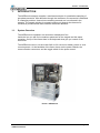
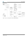
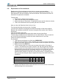
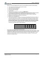
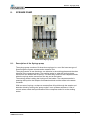
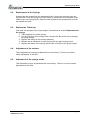
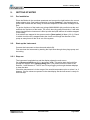
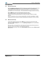
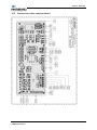
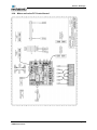
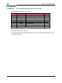
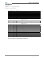
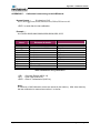
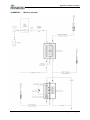
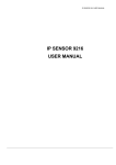
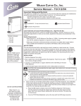
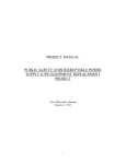
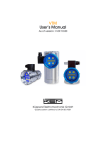
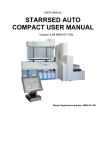
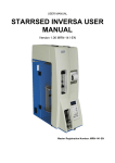
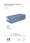
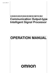
OPERATION AND
TECHNICAL MANUAL
© Copyright Mechatronics
Master Register Number:
Dated:
Issue No:
MRN-053
December 2010
9.1
Manufacturer: Mechatronics Manufacturing BV
Phone
+31 (0) 229 - 29 11 29
Fax
+31 (0) 229 - 24 15 34
E-mail
[email protected]
Homepage
www.mechatronics.nl
Postal Address
P.O. Box 225,
1620 AE Hoorn
The Netherlands
Office Address
De Corantijn 13
1689 AN Zwaag
The Netherlands
© Copyright Mechatronics
All rights reserved.
Subject to changes without prior notice.
Rights of modification reserved.
Issued by the After sales Department of Mechatronics.
Amendment record
AMENDMENT RECORD SHEET
Issue No
Date
Preliminary
1
2
3
July 2001
Aug 2001
Nov 2001
Jan 2002
4
5
May 2002
August 2003
Section 9
Section 2, 4,5 and 9
6
November
2004
July 2006
November
2007
February
2008
December
2010
All
7
8
9
9.1
MRN-053 Issue 9.1
AiRRmonia Manual
Revised Section(s)
Revised Page
No(s)
All
All
Section 14
New section
All
All
Section 14.2 and
14.3
Index
Section 9
The complete
sections
All
Authorised
H.E. van Dijk
H.E. van Dijk
H.E. van Dijk
H.E. van Dijk
H.E. van Dijk
H.E. van Dijk
H.E. van Dijk
Section 5, 14,
See history list
H.E. van Dijk
H.E. van Dijk
Section 4.3
H.E. van Dijk
Section 9.3.1
December 2010
K factor calculation
corrected
H.E. van Dijk
Page VII
History of the manual
HISTORY OF THE MANUAL
Date
July 2001.
Issue
Changes
Preliminary Start manual to build for scratch
Spelling and layout adjustments
Aug 2001
Issue 1
Corrections in section 6 & 7
New drawings section 14
Latest Update on the photo's
Corrections in section 2.3
Corrections in section 3
Nov 2001
Issue 2
Corrections in section 5
Corrections in section 9
Corrections in section 11
Rewritten section 13
Add Index
Jan 2002
Issue 3
Section 14 Drawing Computer board and
Valve PC control board
Change make up of section 9
May 2002
Issue 4
New drawings section 14
Section 2. Small corrections in the
introduction
Section 4 new labels are issued
Section 5 Key board add new menu
August 2003
Issue 5
structure for software version 1.09 Auto
calibration
Section 9 Getting started and auto
calibration
Revision Mechatronics house style
November
Issue 6
Corrections in all sections
2004
July 2006
November
2007
Issue 7
Issue 8
Section 5 Update the menu layout
Remove appendix H Flow diagram
Update drawing measure principal appendix
F
Section 14 add drawing AMIN100065
Section 2.3.1. Part number change
AMIN010008 for AMIN010015
Section 6.1. Take off all tubing
Section 6.2. Take off all tubing and changed
part number AMIN010008 for AMIN010015
Section 7.1. Take off all tubing.
Section 8.6. is removed.
Section 9.2.1. removed the instrument will
settle….
Section 9.3.1. The formula
Authorised
H. E van Dijk
H. E van Dijk
H. E van Dijk
H.E. van Dijk
H.E. van Dijk
H.E. van Dijk
H.E. van Dijk
H.E. van Dijk
H.E. van Dijk
TCC50 = (TCC500 − TCC0 )xK − TCC0
Corrected by
TCC50 = (TCC 500 − TCC 0 ) + K − TCC 0
MRN-053 Issue 9.1
AiRRmonia Manual
December 2010
Page VIII
History of the manual
February
2008
December
2010
Issue 9
Section 9.3.3.
Detector 2 must be in the same range as
Detector 1 plus 60 till 200 mV.
Detector 2 must be in the same range as
Detector 1 plus 60 till 200 mV.
Sections 9.3.4. and 9.3.5. removed detector
1 must…. and the Tcc is ….
Section 11.1.2. removed 750 hour
maintenance
Section 4.3 Prepare 50 ppB calibration
liquid.
Correction on preparation 50ppB 10 parts
must be 9 parts
TCC 50 = (TCC 500 − TCC 0 ) + K − TCC 0
Issue 9.1
MRN-053 Issue 9.1
AiRRmonia Manual
corrected by
TCC 50 = (TCC 500 − TCC 0 ) * K + TCC 0
December 2010
Page IX
CONTENTS
Contents
Page No.
AMENDMENT RECORD SHEET ..............................................................................................VII
HISTORY OF THE MANUAL....................................................................................................VIII
CONTENTS................................................................................................................................ 10
1.
2.
3.
4.
5.
6.
7.
8.
9.
INTRODUCTION ................................................................................................................. 13
1.1. SYSTEM OVERVIEW....................................................................................... 13
INSTRUMENT DESCRIPTION ........................................................................................... 16
2.1. AIRRMONIA...................................................................................................... 16
2.2. TECHNICAL SPECIFICATION ......................................................................... 16
2.3. TOOLS AND ACCESSORIES .......................................................................... 17
2.3.1. Part list ........................................................................................... 17
INSTALLATION .................................................................................................................. 18
3.1. PRE INSTALLATION ........................................................................................ 18
3.2. FIELD INSTALLATION ..................................................................................... 18
REAGENTS ........................................................................................................................ 19
4.1. STORAGE ........................................................................................................ 19
4.2. CONTAINERS .................................................................................................. 19
4.3. PREPARE THE 50 PPB CALIBRATION LIQUID. ............................................ 19
4.4. LABELS ............................................................................................................ 20
KEYBOARD........................................................................................................................ 21
5.1. MENU STRUCTURE AIRRMONIA................................................................... 22
5.2. MENU ITEMS ................................................................................................... 24
DETECTION BLOCK .......................................................................................................... 25
6.1. REPLACEMENT OF THE ION EXCHANGE COLUMN.................................... 25
6.2. REPLACEMENT OF THE MEMBRANE ........................................................... 26
6.3. REPLACEMENT OF THE TEMPERATURE SENSOR .................................... 27
6.4. REPLACEMENT OF THE DETECTOR SENSOR............................................ 27
SAMPLE BLOCK................................................................................................................ 28
7.1. REPLACEMENT OF THE MEMBRANE ........................................................... 28
SYRINGE PUMP ................................................................................................................. 30
8.1. DESCRIPTION OF THE SYRINGE PUMP....................................................... 30
8.2. REPLACEMENT OF THE SYRINGE................................................................ 31
8.3. REPLACE THE TEFLON TIPS......................................................................... 31
8.4. ADJUSTMENT OF THE SENSORS ................................................................. 31
8.5. ADJUSTMENT OF THE SYRINGE STROKE................................................... 31
GETTING STARTED .......................................................................................................... 32
9.1. PRE INSTALLATION ........................................................................................ 32
9.2. START-UP THE INSTRUMENT ....................................................................... 32
9.2.1. Step one ......................................................................................... 32
9.2.2. Step two ......................................................................................... 33
9.3. CALIBRATION PROCEDURE .......................................................................... 33
9.3.1. Automatic calibration ...................................................................... 33
MRN-053 Issue 9.1
AiRRmonia Manual
December 2010
Page 10
10.
11.
12.
13.
14.
15.
9.3.2. Service calibration .......................................................................... 35
9.3.3. Calibration of blank value ............................................................... 35
9.3.4. Calibration of 50 ppB value ............................................................ 36
9.3.5. Calibration of 500 ppB value .......................................................... 36
9.4. MEASUREMENT START ................................................................................. 37
9.5. MEASUREMENT STOP ................................................................................... 37
9.6. SETTING / SERVICE........................................................................................ 38
9.6.1. Settings .......................................................................................... 39
9.6.2. Service ........................................................................................... 40
SYSTEM MESSAGES ........................................................................................................ 41
10.1. SYSTEM MESSAGES ...................................................................................... 41
10.2. ERROR MESSAGES........................................................................................ 41
MAINTENANCE .................................................................................................................. 42
11.1. MAINTENANCE TIME SCHEDULE.................................................................. 42
11.1.1. <150 hour ....................................................................................... 42
11.1.2. 1500 hour ....................................................................................... 42
11.1.3. 2100 hour ....................................................................................... 42
11.1.4. 4500 hour ....................................................................................... 42
11.1.5. 8500 hour ....................................................................................... 43
DATA MANAGEMENT ....................................................................................................... 44
12.1. RS232 CONNECTION...................................................................................... 44
12.2. DATA STORAGE.............................................................................................. 44
12.3. DOWN LOAD DATA ......................................................................................... 44
12.4. PROCESS THE DATA...................................................................................... 45
UPLOAD NEW SOFTWARE .............................................................................................. 46
13.1. INSTALL THE DOWNLOAD SOFTWARE........................................................ 46
13.2. INSTALL THE INTERFACE.............................................................................. 47
13.3. CONNECT THE INTERFACE TO THE PC BOARD......................................... 47
13.4. RUN THE UPLOAD SOFTWARE..................................................................... 47
DRAWINGS ........................................................................................................................ 50
14.1. LIQUID FLOW................................................................................................... 50
14.2. LIQUID FLOW (PRESS) ................................................................................... 51
14.3. CONNECTORS ON THE COMPUTER BOARD .............................................. 52
14.4. MOTOR AND VALVE PC CONTROL BOARD. ................................................ 53
APPENDIX SECTION OF MRN-053 AIRRMONIA ............................................................. 55
APPENDIX A -
CONNECTORS............................................................................................ 56
APPENDIX B -
PC SERIAL DATA CABLE FOR DOWN LOAD THE DATA ...................... 57
APPENDIX C -
CONTROL COMMANDS. ............................................................................ 58
APPENDIX D -
AIRRMONIA DATA STRING FORMAT....................................................... 61
APPENDIX E -
CALIBRATION FORMAT STRING TO THE AIRRMONIA.......................... 62
APPENDIX F -
MEASURE PRINCIPAL ............................................................................... 63
APPENDIX G -
MENU STRUCTURE PAGE 1, 2 AND 3...................................................... 64
ALPHABETICAL INDEX ........................................................................................................... 68
MRN-053 Issue 9.1
AiRRmonia Manual
December 2010
Page 11
Contents
MRN-053 Issue 9.1
AiRRmonia Manual
December 2010
Page XII
Section - Introduction
1.
INTRODUCTION
The AiRRmonia analyser contains a membrane sampler for quantitative sampling of
gas-phase ammonia. After diffusion through the membrane, the ammonia is absorbed
in a sampling solution. Ammonium-containing aerosols are not collected in the
sampler. The sample solution is pumped continuously through the detector for
conductivity measurement after selective membrane diffusion.
1.1.
System Overview
The AiRRmonia is installed in an aluminium weatherproof box.
Inside the box you will find a container apartment for the reagent and the waste
container. On top of the frame there is the keyboard what give you control of the
instrument.
The AiRRmonia can run on the mains 240 or 120 volt and on battery power or even
on solar panels. At the backside of the frame, there are the power chassis, the
communication connectors, and the toggle switch for the power control.
Photo 1 AiRRmonia
MRN-053 Issue 9.1
AiRRmonia Manual
December 2010
Page 13
Section - Introduction
MRN-053 Issue 9.1
AiRRmonia Manual
December 2010
Page 14
Section - Introduction
MRN-053 Issue 9.1
AiRRmonia Manual
December 2010
Page 15
Section - Instrument description
2.
INSTRUMENT DESCRIPTION
2.1.
AiRRmonia
This instrument is a Gas-phase ammonia-measuring instrument. The unit is user
friendly and works with ready to use reagents. This feature gives the instrument good
reproducible results over a long period of time. The E-EPROM storage capacity is
sufficient to leave the AiRRmonia in the field for 3-week period.
The AiRRmonia has the potential to detect from 0,1µg/ m³ up to 100µg/ m³
(preliminary data).
The instrument has a build in 2-points auto-calibration set. The mass Flow Controlled
sampling has a flow of 1l/min. The measure period is time controlled and the highest
sample resolution is one sample every 1 minute.
2.2.
Technical specification
Dimensions
Length
Width
Height
Weight
Weight for the reagent
Power supply
Battery operated
Real time data
Output RS- 232
Selectable
MRN-053 Issue 9.1
AiRRmonia Manual
62 cm
40 cm
50 cm
25 kg is exclusive the liquid.
1.5 kg for the liquid.
90-264VAC 50/60 Hz; 10VA
12 VDC, 8VA.
Available every second.
19200-8-N-1 default setting.
9600-8-N-1
4800-8-N-1
December 2010
Page 16
Section - Instrument description
2.3.
Tools and Accessories
For maintenance is a standard toolkit with a selection of screwdrivers and hex keys in
the range from 2 mm till 5 mm. A cutter for cutting Tie-raps, a pair of scissors and
some hand gloves for changing the membrane.
for starting the flow from the bottles into the system use a syringe, (AMIN109003).
2.3.1. Part list
The following part numbers can be order
Order number
QWLV030014
QWLV030015
QWLV030016
QWLV030018
QWLV040001
QEPC079001
AMIN010015
AMIN019006
AMIN020010
AMIN039011
AMIN049020
Part description
Diluter Syringe 250 μl
Diluter Syringe 2500 μl
Teflon tips for the 250 μl syringe units.
Teflon tips for the 2500 μl syringe units.
Air filter
Upload tool for instrument software
Membrane for Detection block.
Resin for the detection block
Membrane for Sample block.
Syringe pump motor
CO2 filter assembly
Table 1 Part list
MRN-053 Issue 9.1
AiRRmonia Manual
December 2010
Page 17
Section - Installation
3.
INSTALLATION
3.1.
Pre Installation
Before the AiRRmonia can be used for the first time, you have to do a pre set-up of
the instrument. In the pre set-up, you have to rinse, fill the tubing and the syringes
with reagents from the containers without trapping air bubbles.
To fill the system and do the calibration it will take some time. If everything is done
correctly the instrument is ready for use.
For more details, see section Getting started.
3.2.
Field Installation
To avoid any false measurements in the field do not touch the bottle connectors with
your hands. Recommendation is to use hand gloves.
Check all the tube connections and there are no air bubbles trapped in the tubes
and/or in the syringes.
Check the levels in the containers. The containers can hold liquid for 6 days. After
detection of empty bottle the instrument will stop.
Check the level of the waste container. When the detection ‘waste container full’ the
instrument will stop.
Make sure there is a free passes way of air to the air inlet of the AiRRmonia.
Connect the AiRRmonia to the power source, switch on and start the measurement.
The instrument will show the first menu in the display.
For details and a full description of the entire menus, see section Getting started &
Keyboard.
MRN-053 Issue 9.1
AiRRmonia Manual
December 2010
Page 18
Section -Reagents
4.
REAGENTS
There is no need for mixing the fluid; the reagents are ready for use.
4.1.
Storage
Store the regent in a 4 - 8 °C cool place.
4.2.
Containers
The following reagents are supplied in bottles for the AiRRmonia
QRR029001 De-mineralised water
0.25 L
QRR029024 De-mineralised water
1L
QRR029025 De-mineralised water
10L
QRR029002 Sodium Hydroxide solution
0.25L
QRR029022 Sodium Hydroxide solution
1L
QRR029026 Standard 500 ppB ammonium
0.25 L
QRR029027 Standard 500 ppB ammonium
1L
QRR029028 Standard 50 ppB ammonium
0.25 L
Waste container
2.5 L
4.3.
Prepare the 50 ppB calibration liquid.
To make the 50 ppB solution, take 1 part of the 500 ppb and 9 part of de-mineralised
water and mix well.
The 50 ppB solution has a short expire date. Prepare the 50 ppB when needed for the
calibration.
MRN-053 Issue 9.1
AiRRmonia manual
December 2010
Page 19
Section - Regents
4.4.
Labels
The containers have the following labels:
Demineralized
water
Sodium Hydroxide
solution
H2O
NaOH
store at 4-8°C
Waste
store at 4-8°C
Standard 500 ppb
ammonium
Standard 50 ppb
ammonium
500ppb NH4
50ppb NH4
store at 4-8°C
store at 4-8°C
Figure 1 Stickers
MRN-053 Issue 9.1
AiRRmonia manual
December 2010
Page 20
Section– Keyboard
5.
KEYBOARD
7
8
9
F1
4
5
6
F2
1
2
3
F3
0
F1
F2
F3
Function key 1
Function key 2
Function key 3
Escape key
Back space
Enter key
MRN-053 Issue 9.1
AiRRmonia manual
December 2010
Page 21
Section– Keyboard
5.1.
Menu structure AiRRmonia
MRN-053 Issue 9.1
AiRRmonia manual
December 2010
Page 22
Section– Keyboard
Note: There is an A4 sized page in the appendix Menu Structure
MRN-053 Issue 9.1
AiRRmonia manual
December 2010
Page 23
Section - Keyboard
5.2.
Menu items
Navigating through the menu’s
During normal operation, the main menu is displayed. To access submenus and
functions, press the item number shown at the front of the line.
Press ESC to return to previous menus and to abort functions.
Function keys F2 and F3 are reserved for future purposes.
The submenus are listed with menu number (see overview in section 5.1)
The legend is;
Bold text in line the display
[Bold text]
Menu (4-1)
Use the number keys 4 and 1 to go to the menu
Press the function key F2
<F2>
Menu (4-1-4-1) means the following keystrokes:
Key 4 [Setting/Service]
Key 1 [Settings]
Key 4 [More]
Key 1 [Running mean/min]
MRN-053 Issue 9.1
AiRRmonia manual
December 2010
Page 24
Section - Detection Block
6.
DETECTION BLOCK
Photo 2 Detection block
6.1.
Replacement of the Ion exchange column
Replacement of the ion column must be done in a proper accommodation.
First, change the Ion exchange column before you change the membrane.
Take the Detection block out of the instrument.
The best way;
• Disconnect to bottle from the system
• Take off all the tubing from the detection block.
• Disconnect the two connectors. (Temperature sensor and the detector sensor)
• Take out the Detection block by loosing the two hex screws.
Take the Detection block in front of you. Turn the detection block so you have access
to the filling cap of the Ion exchange column. Unscrew the cap and suck carefully the
old Ion exchange column out of the block by using a syringe. Be careful not to loose
the two glass filters.
Fill the Ion exchange column with the new resin by using a syringe AMIN019006. Be
careful when you fill the tube and watch the two glass filters that they are still in place.
Replace the cap and close it careful, the remaining liquid has to find his way through
the filters to the membrane.
Replace the Detection block or start to change the membrane.
MRN-053 Issue 9.1
AiRRmonia manual
December 2010
Page 25
Section - Detection Block
6.2.
Replacement of the membrane
Replacement of the membrane must be done in a proper accommodation.
Before you replace the membrane, check if you want to change the ionisation. The
best sequence is first the ionisation, then the membrane. See the above section for
instruction for replace the ionisation.
The best way;
• Disconnect to bottle from the system
• Take off all the tubing from the detection block.
• Disconnect the two connectors. (Temperature sensor and the detector sensor)
• Take out the Detection block by loosing the two hex screws.
Now you have the Detection block in front of you.
Turn around the block and remove the 10 screws.
Turn the block tentative around again and hold the sections of the block together.
Between the membrane and block, there are two glass filters and we don't want to
loose them.
Take off the plastic upper part.
Remove the old membrane and please think about the two glass filters.
The best way to handle the new membrane is to use hand cloves. This is to prevent
any touch with the membrane to avoid any false measurement in the field.
Clean the top block with water.
Dry the block.
• Take the new membrane out of the bag. AMIN010015
• Place the new membrane; make sure there are no hairs or dust on the block.
• Replace the plastic upper part, turn the Detector block and replace the screws.
• First tie the screws hand tied.
• Tie the screws gentle in a cross over movement (See table). First start at
number 1 and tie this screw next is number 2 etc. By doing this we divide the
pressure equal over the metal block. Do not over do the tiding of the screws
because all the force will be in the plastic block. By over doing this you take a
risk that the sample block will cleave after a while. You can use a torsion
spanner with a moment of 100 Ncm to tie up the screws. If everything went
well, you can see along the edge a slightly colouring of the white colour of the
membrane.
Number of crossing
1
7
9
3
Screws in the block
O
O
O
O
Screws in the block
O
O
O
O
Number of crossing
5
4
10
8
Sequence of cross movement of the screws
•
6
O
O
2
Replace the Detector block in the instrument and connect the two connectors
and the tubing in the correct places.
MRN-053 Issue 9.1
AiRRmonia manual
December 2010
Page 26
Section - Detection Block
6.3.
Replacement of the temperature sensor
This is a manufactory job. Please return instrument to Mechatronics.
Order a replacement for the Detector sample block.
6.4.
Replacement of the Detector sensor
This is a manufactory job. Please return instrument to Mechatronics.
Order a replacement for the Detector sample block.
MRN-053 Issue 9.1
AiRRmonia manual
December 2010
Page 27
Section - Sample block
7.
SAMPLE BLOCK
Photo 3 Sample block
7.1.
Replacement of the membrane
Replacement of the membrane must be done in a proper accommodation.
The best way is;
• Disconnect the bottle from the system.
• Take off al the tubing the valve block.
• Take off the input tube with number 1 from the sample block.
• Take off the tube with the filter from the mass flow control unit.
• Make loose the valve unit by unscrewing the two hex screws. The valve unit is
hanging loose in the instrument.
• Take out the Sample block by loosing the two hex screws and shift in the slot
and take it out the instrument.
MRN-053 Issue 9.1
AiRRmonia manual
December 2010
Page 28
Section - Sample block
Now you have the Sample block in front of you with filters connectors on both sides.
•
•
•
•
•
•
•
•
•
•
•
Turn around the block and remove the 10 screws.
Take off the heavy metal plate.
Remove the old membrane.
Clean the block with water.
Dry the block.
Take the new membrane out of the bag. AMIN020010.
The best way to handle the new membrane is to use hand cloves. This is to prevent
any touch with the membrane to avoid any false measurement in the field.
Place the new membrane; make sure there are no hairs or dust on the block.
Replace the metal block and put the screws back.
First tie the screws hand tied.
Tie the screws gentle in a cross over movement (See table). First start at number 1
and tie this screw next is number 2 etc. By doing this we divide the pressure equal
over the metal block. Do not over do the tiding of the screws because all the force
will be in the plastic block. By over doing this you take a risk that the sample block
will cleave after a while. You can use a torsion spanner with a moment of 100 Ncm
to tie up the screws. If everything went well, you see along the edge a slightly
colouring of the white colour of the membrane.
Number of crossing
1
7
9
3
Screws in the block
O
O
O
O
Screws in the block
O
O
O
O
Number of crossing
5
4
10
8
Sequence of cross movement of the screws
6
O
O
2
Now replace the Sample block in the instrument.
Connect the tube with the filter on the mass flow block and the tube with number 1 to the
sample block. Replace the valve block and connect the tubing in the correct place. Tube
number 14 is at the bottom location and tube number 13 is at the top location. Tie the
screws of the valve block. Do not over do this because it is plastic. Tie the now the
screws of the sample block.
MRN-053 Issue 9.1
AiRRmonia manual
December 2010
Page 29
Section - Syringe pump
8.
SYRINGE PUMP
Photo 4 the Syringe pump.
8.1.
Description of the Syringe pump
The syringe pump consists of 2 times three syringes in a row. We have two type of
flows trough the system a waste and a measure flow.
The syringe works in two directions, one direction is the sucking phase and the other
direction is the compress phase. The sucking stroke is, when the syringe piston
moves from the bottom end to the top. The other way around is the compress stroke,
when the syringe stroke moves from the top end to the bottom.
The sucking stroke is taking the liquid out of the bottles. The compress stroke is
pressing the liquid to the Sample and Detection block and the waste to the waste
container.
With two sets of syringe, we have a constant flow of liquid through the sample and
detection block by moving the "pump engine" in an up/down sequence. A set of
control valves switch the liquid direction to the compress stroke or to the sucking
stroke.
MRN-053 Issue 9.1
AiRRmonia manual
December 2010
Page 30
Section Syringe block
8.2.
Replacement of the Syringe
Unscrew the two screws from the attachment block. Unscrew the syringe from the
syringe block. Click the syringe out of the holder by using some force. Beware of the
rubber ring in the syringe block. Place the new syringe on the syringe block and refit
the attachment block.
8.3.
Replace the Teflon tips
First, take the syringe out the "pump engine” as described in section Replacement of
the syringe.
1. Take the piston out of the syringe
2. Cut the Teflon tip of the plunger with a sharp knife. Be careful not to damage
the metal plunger
3. Replace the old tip for the new tip assembly
4. Moisten the tip with water to ease the tip back into glass syringe barrel
5. Replace the piston in the syringe and set the unit back in the "pump engine".
8.4.
Adjustment of the sensors
Those adjustments are done by Mechatronics in the factory. There is no need to
make adjustments in the field.
8.5.
Adjustment of the syringe stroke
This adjustment is done by Mechatronics in the factory. There is no need to make
adjustments in the field.
MRN-053 Issue 9.1
AiRRmonia manual
December 2010
Page 31
Section - Getting started
9.
GETTING STARTED
9.1.
Pre installation
Place the Bottles in the container apartment and connect the right bottle to the correct
bottle adapter plug. (See bottle connection in section Drawing). Use hand gloves to
avoid hand contact with the tubing of the bottle adapters to avoid false readings in the
flied.
To get the liquid out of the bottle use syringe AMIN109003 with a soft tube at the end
and suck the liquid out of the bottle. The rest is done by gratify fill and time, it will take
some time before the instrument is filled up with the liquid without air bubbles trapped
in the tubing.
If air bubbles are trapped in the system use the [Vent option] in Menu (2-2-4). Check
in which circuit the air is trapped select the circuit and change the direction of the
pump as many times till the air is out of the system.
9.2.
Start-up the instrument
Connect the instrument to the mains and switch ON.
First we clean the instrument by starting the liquid flow through the syringe pump and
the tubing.
9.2.1. Step one
The instrument is switched on and the display shows the main menu.
Go to [Pump on/off] Menu (2-2-1) and press <F2>. This action start the liquid flow
through the system Go to [Display data] Menu (2-4) and monitor the value of the
Detector 1 and Detector 2. The F2 and F3 keys toggle you through the data displays
to view the data.
Check the temperature is in the range of the outside temperature plus or minus 2 or 3
degrees. If those values are present in the data display we the instrument is ready for
the next step.
MRN-053 Issue 9.1
AiRRmonia manual
December 2010
Page XXXII
Section - Getting started
9.2.2. Step two
Switch on the air pump.
Return to the main menu by pressing the <ESC> key. Switch on the [Air pump]
Menu (2-1). This is a toggle function; pressing F2 the pump is on and press F2 again
the pump is off.
Return to the display to view the data Menu (2-4). Check the increase of the voltage
on Detector-2. Next check is the airflow this must be 1 litre/minute.
Press <ESC> key until you reached the main menu. Select now [Measure] Menu (1)
and use the F2 or the F3 key to toggle through the data display and check the airflow
value.
There is now airflow through the instrument and this flow has effect on the value of
the
Detector-2. In about 10 minutes you will see a increase of the Detector-2 value. If this
is in order the instrument is ready for calibration. Switch the [Air pump] Menu (2-1)
9.3.
Calibration procedure
9.3.1. Automatic calibration
Parameter settings
Menu (3-1-1) [Start after]
This value shows after how many hours the instrument will start to do the next
automatic calibration. Hours are show in whole numbers in the range 1 …240. When
select 0 no calibration will be is done.
Menu (3-1-2) [Set cal. Period]
The value shows the waiting period between the next automatic calibration.
Example:
If the number is 5 the next calibration will start after 5 hours.
MRN-053 Issue 9.1
AiRRmonia manual
December 2010
Page 33
Section - Getting started
Menu (3-1-3) [Set K constant]
Factor K is used for the 50 ppB calibration value according the following formula:
K=
TCC50 − TCC0
TCC500 − TCC0
TCC 50 = (TCC 500 − TCC 0 ) * K + TCC 0
The K factor is established on 0.247.
The Zero calibration takes 120 minutes.
A new value of the TCC0 will be accepted if the numbers are in a range of 1 and
300. If the values are not in the range the last calibration figures will be used.
The 500 calibration takes 120 minutes
A new value of the TCC500 will be accepted if the numbers are in a range of 500 and
2000. If the values are not in the range the last calibration figures will be used.
The TCC will be the mean calculated value for the set-up period what is set in
Menu (4-1-4-1) [Running mean/min.]
MRN-053 Issue 9.1
AiRRmonia manual
December 2010
Page 34
Section - Getting started
9.3.2. Service calibration
We have to do 3 calibrations
1. Find the blank value
2. Find the 50 ppB value
3. Find the 500 ppB value
To perform this calibration we select the [Service cal]. Menu (3-2)
Use the <ESC> key to return to the Main menu.
Select [New cal] Menu (3-2-1). Select which one of the value you want to calibrate,
Start logging , and observe the raw data in Progress or see in New value your new
Tcc value. If you values of the Tcc are in your acceptation press 2 in Menu (3-2-11/2/3) to accept the new value. There is an option in this menu to put a manual value
in for that calibration range.
After all calibrations are done, press <ESC> and select Save new calibration. Now
the instrument is ready for use with the new set of calibration values.
Be aware as soon you out of the menu 14 structure the calibration is stopped. If this
happened you have to restart the calibration for one of the values.
9.3.3. Calibration of blank value
Select [0 ppB] Menu (3-2-1-1). In [Progress 0 ppB] Menu (3-2-1-1-1) you see the
raw data for that moment.
Monitor the values in the Progress display;
•
Detect temperature is the temperature of the detection block.
•
The Tcc is the value of the Detector 2 minus Detector 1 plus the temperature
correction and must be in a range 60-200.
MRN-053 Issue 9.1
AiRRmonia manual
December 2010
Page 35
Section - Getting started
9.3.4. Calibration of 50 ppB value
For this calibration you need the container with the 50 ppB solution.
Take the bottle adapter out of the container what holds the 500 ppB solution and put
this in the bottle with the 50 ppB solution.
Select [50 ppB] Menu (3-2-1-2). In [Progress 50 ppB] Menu (3-2-1-2-1) you see the
raw data for that moment.
Monitor the values in the Progress display;
•
Detect temperature is the temperature
•
Detector 1 must be in the range of 100 till 200 mV
•
The Tcc is the 200 ±20% of the value Detector-1.
The value of Tcc can more or less be checked by subtracts Detector 2 and Detector
1. This gives you in indication of the acceptation of the value.
The duration of the calibration will take a minim of 20 minutes.
The calibration is correct if the reading is a stable.
9.3.5. Calibration of 500 ppB value
Make sure the bottle adapter is in the container with the 500 ppB solution.
Select [500 ppB] Menu(3-2-1-3). In [Progress 500 ppB] Menu (3-2-1-3-1) you see
the raw data for that moment.
Monitor the values in the Progress display;
•
Detect temperature is the temperature of the detection block.
•
Detector 1 must be in the range of 100 till 200 mV
•
The Tcc is the 800 ±20% of the value Detector-1.
The value of Tcc can more or less be checked by subtracts Detector 2 and Detector
1. This gives you in indication of the acceptation of the value.
The duration of the calibration will take a minim of 20 minutes.
The calibration is correct if the reading is a stable.
MRN-053 Issue 9.1
AiRRmonia manual
December 2010
Page 36
Section - Getting started
9.4.
Measurement start
If all the calibration values are stored in memory you can start the measure sequence.
Set your [Measure period] Menu (4-1-2) to desired period. The instrument is
collecting data every second and calculates the average over the set period of time
(selectable from 1 till 99 minutes). This calculated time average is stored in memory.
Press <ESC> key until you are returned in the mean menu.
Press Measure Menu (1) and the instrument starts to measure.
The air pump and the syringe pump are running, the data is stored in the data
memory.
When you press key <1> you come automatically in the data view displays. Toggle
through the menus to select the desired data display by using the F2 and or F3 key.
9.5.
Measurement stop
To stop the measurement press the <ESC> key and return to the manual mode.
Switch off the [Air pump] Menu (2-1), the [Syringe pump] Menu (2-2-1) and select
the pump on/off.
Be aware after you stop the flow in the instrument for some time the instrument can
generate errors on the Detector and temperature sensors.
You can reset this errors via the menu [Settings/Service] in the menu [Clear errors]
Menu(4-2-3).
MRN-053 Issue 9.1
AiRRmonia manual
December 2010
Page 37
Section - Getting started
9.6.
Setting / Service
In this section the setting and the service mode of the instrument.
In the [Settings] Menu (4-1) the following changes or settings can be altered:
-
Data and time
Measure period
Clear the memory
More options
Running mean/min
Auto start
Logging on/off
- More options
- Fan on/off
- Baud rate
In the [Service] Menu (4-2) the following service are available:
-
Status
Errors
Clear errors
Software version
MRN-053 Issue 9.1
AiRRmonia manual
December 2010
Page 38
Section - Getting started
9.6.1. Settings
[Date and time] Menu (4-1-1)
Set the correct date and time or alter the date or time. When changing one of the
settings, you have to continue to fill in the date until the last setting input.
[Measure period] Menu (4-1-2)
Set time period, selectable from 01 till 99 minutes. The instrument is collecting data
every second and calculates the average over that set time period and stored the
calculated time average is memory.
[Clear the memory] Menu (4-1-3)
Clear the memory. All collected data is cleared and the last stored calibration values
are restored. A maximum of 99 Calibration values are stored in the memory. After
clear memory the last calibration is restored as number 1 in the calibration list.
[More options] Menu (4-1-4)
The following settings can be made or select.
[Running mean/min] Menu (4-1-4-1)
Set period of time, selectable from 0.5 till 60 min.
[Auto start] Menu (4-1-4-2)
Is a future to restart after a power failure, is selectable Auto start yes or no. This
setting is stored in memory
[Logging on/off]. Menu (4-1-4-3)
Select logging data on or off.
[More options] Menu (4-1-4-4)
The following settings can be made or select.
[Fan On /Off] Menu (4-1-4-4-1)
Is by default on and can be switch off. This setting is stored in memory.
[Baud rate] Menu (4-1-4-4-2)
Is selectable 4800, 9600, 19200 with fixed parameters 8-n-1.
MRN-053 Issue 9.1
AiRRmonia manual
December 2010
Page 39
Section - Getting started
9.6.2. Service
[Status] Menu (4-2-1) is not available.
[Errors] Menu (4-2-2) is not available.
[Clear errors] Menu (4-2-3) you press <3> this will cancel the error or alarm of the
instrument.
[Software version] Menu (4-2-4)
MRN-053 Issue 9.1
AiRRmonia manual
December 2010
Page 40
Section - System Messages
10.
SYSTEM MESSAGES
10.1. System messages
The system gives two types of messages, the system and the error messages
System list
System number
NN
System description
Not available yet
10.2. Error messages
Error list
Error number
Error 1
Error 2
Error 3
Error 4
Error 5
Error 6
Error description
Bottle empty or waste full
Temperature out of range
Detector I out of range
Detector II out of range
Data Memory full
3 point calibration Memory full
Table 2 Error list
MRN-053 Issue 9.1
AiRRmonia manual
December 2010
Page 41
Section - System Messages
11.
MAINTENANCE
The instrument needs maintenance to keep the instrument in top condition. On this
moment there is not enough flied information available to set-up a maintenance
schedule. We recommend the following schedule for this moment.
11.1. Maintenance time schedule
The following schedule can be set-up for the maintenance.
Running
Hours
Description of the maintenance
<150 1 week period
1500 2 month period
2100 3 month period
4500 6 month period
8500 12 month period
Table 3 Maintenance schedule
11.1.1. <150 hour
•
•
•
•
•
Down load the data
Replace the regents
Clean the waste bottle
Check the calibration values
Run a calibration check
11.1.2. 1500 hour
Clean the cyclone pot of the sample block with De-mineralised water
11.1.3. 2100 hour
1500 hour maintenance plus:
• Replace the syringe which pumps the lye if needed.
Part number AMIN030149
11.1.4. 4500 hour
2100 hour maintenance plus:
Replace the Teflon tips in the syringe
or replace the old syringe by new ones.
Replace the air pump
Replace the disk filter
Replace the membrane of the detection
block
Replace the membrane of the sample block
MRN-053 Issue 9.1
AiRRmonia manual
December 2010
QWLV030006, QWL030007
AMIN030149, AMIN030150
AMIN040130
QWLV040001
AMIN010015
AMIN020010
Page 42
Section - Maintenance
11.1.5. 8500 hour
Is the 4500 hour maintenance
The Master flow controller has no maintenance or calibration schedule
MRN-053 Issue 9.1
AiRRmonia manual
December 2010
Page 43
Section - Data management
12.
DATA MANAGEMENT
The AiRRmonia has a standard RS232 date communication with default settings of
19200-8-n-1.
The data is storage in E-Eprom.
The data is standard ACII format and is readable in any communication software such
as ProComm or Hyper Terminal. The connection cable between the Instrument and
the PC is a standard 9 to 9 pin 1 in 1 computer cable, what can be obtained in any PC
shop.
12.1. RS232 connection
The data string is in ACII format. Data is sending every 1-second to the serial output.
Set-up your communication parameters to 19200 Baud, 8 charters, no party bit and 1
stop bit. See also your software instructions of the communications software
12.2. Data storage
The data is held in instrument E-Eprom with storage capacitates of 512 Kbytes.
This data memory can hold more then a 32,000 samples.
An example:
One samples every minute x 60 x 24 hours x 7 days that makes 10,080 samples.
12.3. Down load data
Use communication software like ProComm for download the data. Set the correct
parameters in the set up file and download the data into a file. The down load time
from 10.000 samples takes about 6 minutes with a communication speed of 19200
baud. The instrument is during the download period offline.
To start the download sequence from AiRRmonia to Host PC use the key
combination [ESC] and the capital letter < Y >.
When the data is down loaded from the instrument into the PC, the keyboard is frozen
and the instrument does not collecting data.
See for more key combination Appendix Control Commandos.
MRN-053 Issue 9.1
AiRRmonia manual
December 2010
Page 44
Section - Data management
12.4. Process the data
The data file can be import and processed in Excel by using the import wizard. To
change the time and data format select the whole column, go to format cell and select
date in the format of the date time. This will do the trick.
MRN-053 Issue 9.1
AiRRmonia manual
December 2010
Page 45
Section-upload new software
13.
UPLOAD NEW SOFTWARE
The AiRRmonia is software controlled.
The new software can be up-dated by using a micro controller flash program to
upload the software in the memory of the AiRRmonia. (The software program can be
ordered by Mechatronics QEPC079001).
The AVR CD contains the following files.
13.1. Install the download software
This software must be installed on a PC. Insert the CD in the CD drive and select the
set-up program of the CD. See for details your manual how to operate Windows. The
set-up program will install the software via the installation wizard. Follow the wizard
instructions.
After the installation the software and restart your PC the software is ready for use.
MRN-053 Issue 9.1
AiRRmonia manual
December 2010
Page 46
Section-upload new software
13.2. Install the interface
Install the interface with the serial cable to one of the serial ports of your computer.
13.3. Connect the interface to the PC board.
Connect the flat cable from the interface to the PC board in connector J12. This
connector is located direct under the microprocessor.
13.4. Run the upload software
Click on the Start Icon in the Window Icon bar at the bottom of the screen, go to
program and click on the Icon AMTELAVR Tools, click on the AVR studio Icon and
the program will start and show the following screen.
MRN-053 Issue 9.1
AiRRmonia manual
December 2010
Page 47
Section-upload new software
Select in the main task balk the Icon AVR.
The program responds with the next screen
Check the following windows;
Select in the Device window the Atmega103/L
MRN-053 Issue 9.1
AiRRmonia manual
December 2010
Page 48
Section-upload new software
Load the AiRRmonia program file into window FLASH. Use the select button and
select the program hex file. This file can be on your hard disk or on floppy.
Check in the window Programming mode that the option Erase device before
programming and Verify device after programming is set.
Press the key <Program>
MRN-053 Issue 9.1
AiRRmonia manual
December 2010
Page 49
Section - Drawings
14.
DRAWINGS
14.1. Liquid flow
MRN-053 Issue 9.1
AiRRmonia manual
December 2010
Page 50
Section - Drawings
14.2. Liquid flow (press)
MRN-053 Issue 9.1
AiRRmonia manual
December 2010
Page 51
Section - Drawings
14.3. Connectors on the computer board
MRN-053 Issue 9.1
AiRRmonia manual
December 2010
Page 52
Section - Drawings
14.4. Motor and valve PC Control board.
MRN-053 Issue 9.1
AiRRmonia manual
December 2010
Page 53
Section - Drawings
This page is empty
MRN-053 Issue 9.1
AiRRmonia manual
December 2010
Page 54
Section appendix
15.
APPENDIX SECTION OF MRN-053 AIRRMONIA
Appendix A - Connectors
Appendix B - Control Commands
Appendix C - AiRRmonia string format
Appendix D - Measure principal
Appendix E - Menu structure
Appendix F - Flow Diagram
Appendix section
Appendix Page 55
Appendix - Connector cables
APPENDIX A -
CONNECTORS
DC power socket
Pin No.
Appendix section
Function
+12V DC (Brown)
0V (Blue)
Appendix Page 56
Appendix - Connector cables
APPENDIX B -
PC serial DATA CABLE for down load the data
Wiring diagram for a 9 pin 1 to 1 cable.
Pin No.
Male
1
2
3
4
5
6
7
8
9
Signal name
DCD
RxD
TxD
DTR
GND
DSR
RTS
CTS
RI
Information
Data carrier detect
Received data
Transmit data
Data terminal ready
Ground
Data set ready
Request data to send
Clear to send
Ring indicator
Pin No
Female
1
2
3
4
5
6
7
8
9
Down load cable for the software
Is a special cable with dongle and interface is needed for upload new software in the
instrument computer.
Appendix section
Appendix Page 57
Appendix - Control Commands
APPENDIX C -
Control Commands.
AiRRmonia Protocol RS232
Commandos: Host ⇒ AiRRmonia
GetStatus
GetDate
GetMode
GetPeriod
GetLogging
StartMeasure
GetCalData
GetData
Esc ?
Esc D
Esc M
Esc P
Esc L
Esc E
Esc X
Esc Y
Return status (hexadecimal value)
Get date and time
Get mode status
Get measure period
Get data logging setting
Set Measure mode
Get calibration data
Get data
ClearMem
GetSamples
Esc C
Esc N
Software V1.12
Clear memory (Calibration and measurement data is cleared)
Get number of samples stored in memory
GetAirPump
GetLiqPump
GetValve
GetFan
GetHeater
GetInfo
ClearError
StopMeasure
GetCal1
GetCal2
GetCal3
Esc A
Esc Q
Esc V
Esc F
Esc H
Esc I
Esc !
Esc S
Esc 1
Esc 2
Esc 3
Software V1.13
Get air pump setting
Get syringe pump setting
Get valve setting
Get fan setting
Get heater setting
Get software version
Clear error flag + bottle error
Stops air pump + syringe pump
Get calibration 1 (0 ppB) result
Get calibration 2 (50 ppB) result
Get calibration 3 (500 ppB) result
Reset
Resets AiRRmonia (see Change settings)
Esc = Escape (ASCII 27; HyperTerminal = “Escape” key)
Appendix section
Appendix Page 58
Appendix - Control commands
Data returned: AiRRmonia ⇒ Host
GetStatus
?xxxx<CR><LF>
Hexadecimal value (see
Status bits)
D01-01-2001 12:00
1= Measure
2= Calibration
xx = 01 till 99 (minutes)
0 = Logging OFF
1 = Logging ON
Confirmation!
See appendix E for string format
See appendix D for string format
GetDate
GetMode
Ddd-mm-yyyy hh:mm<CR><LF>
Mx<CR><LF>
GetPeriod
GetLogging
Pxx<CR><LF>
Lx<CR><LF>
StartMeasure
GetCalData
GetData
E<CR><LF>
Xdata<CR><LF>
Ydata<CR><LF>
ClearMem
GetSamples
Software V1.12
C<CR><LF>
Confirmation!
Nsamples<CR><LF>
Number of samples (length
variable!)
GetAirPump
Ax<CR><LF>
GetLiqPump
Qx<CR><LF>
GetValve
Vx<CR><LF>
GetFan
Fx<CR><LF>
GetHeater
Hx<CR><LF>
GetInfo
ClearError
StopMeasure
GetCal1
GetCal2
GetCal3
Reset
I Vx.xx<CR><LF>
! <CR><LF>
S<CR><LF>
1:xxxx<CR><LF>
2:xxxx<CR><LF>
3:xxxx<CR><LF>
R<CR><LF>
Software V1.13
0 = Air pump OFF
1 = Air pump ON
0 = Syringe pump OFF
1 = Syringe pump ON
0 = Measure valve
1 = Calibration 1 valve
2 = Calibration 2 valve
0 = Fan OFF
1 = Fan ON
0 = Heater OFF
1 = Heater ON
Vx.xx = software version
Confirmation!
Confirmation!
xxxx = 0000 till 9999
xxxx = 0000 till 9999
xxxx = 0000 till 9999
Confirmation!
<CR> = Carriage Return (ASCII 13)
<LF> = Line Feed (ASCII 10)
Status bits
0 = Air pump
1 = Syringe pump
2 = Fan
3 = Heater
4 = Auto start
5 = Error flag
6 = Bottle
7 = Data memory
8 = Calibration memory
Appendix section
Example: “?001E”
Air pump = OFF
Syringe pump = ON
Fan = ON
Heater = ON
Auto start = ON
Appendix Page 59
Appendix - Control commands
Change settings: Host ⇒ AiRRmonia
Software V1.13
<STX>R<CR>
Reset
SetAirPump <STX>Ax<CR>
SetLiqPump <STX>Qx<CR>
SetValve
<STX>Vx<CR>
SetLogging
<STX>Lx<CR>
SetFan
<STX>Fx<CR>
SetHeater
<STX>Hx<CR>
SetPeriod
SetCal1
SetCal2
SetCal3
SetDate
<STX>Px<CR>
<STX>1xxxx<CR>
<STX>2xxxx<CR>
<STX>3xxxx<CR>
<STX>Ddd-mm-yyyy hh:mm<CR>
Reset AiRRmonia!
0 = Air pump OFF
1 = Air pump ON
0 = Syringe pump OFF
1 = Syringe pump ON
0 = Measure valve
1 = Calibration 1 valve
2 = Calibration 2 valve
0 = Logging OFF
1 = Logging ON
0 = Fan OFF
1 = Fan ON
0 = Heater OFF
1 = Heater ON
xx = 01 till 99 (minutes)
xxxx = 0000 till 9999
xxxx = 0000 till 9999
xxxx = 0000 till 9999
D01-01-2001 12:00
<STX> = Start of Text
(ASCII 2 ; HyperTerminal = “Ctrl + b” keys)
<CR> = Carriage Return (ASCII 13; HyperTerminal = “Enter” key)
The AiRRmonia will respond with sending the new setting (see Data returned).
Appendix section
Appendix Page 60
Appendix - Data string
APPENDIX D -
AiRRmonia data string format.
Normal format …
67 chars incl. crlf
Y;JJJJJ.jjjjj;PP;M;CC;EEEE;TTTT;fff;sssss;SSSSS;-tttt;-0NH4;-0NH3<cr><lf>
<EOT> is send after the last result.
Example …
Y;37106.87032;01;1;01;0002;2766;104;01474;12231;08613;02418;01972
Norm
Y
JJJJJ.jjjjj
PP
M
Elements & details
Start of String
Time and date in 1900 format
PP = Measure period in minutes
M = status bit
CC
EEEE
Calibration number
Status bit
TTTT
TTTT = detected temperature in C
Fff = airflow
Sssss = mV of Detector 1
SSSSS= mV of Detector 2
Ttttt = temperature correct conductivity
NH4 = calculated resulted
NH3 = calculated resulted
CR = carriage return
LF = Line feed
Fff
Sssss
SSSSS
-tttt
-0NH4
-0NH3
CR
LF
Excel format
01 till 99
1= Measure
2= calibration
00 till 99
See Status bits
o
o
C / 100
L/min / 100
mV / 10
mV / 10
mV / 10
ppB / 10
μgr/m3 /100
Table 4 Data string information
<CR> = Carriage Return (ASCII 13)
<LF> = Line Feed (ASCII 10)
<EOT> = End of Transmission (ASCII 4)
Note:
Transmission can be stopped by sending: <Esc><Esc>
Appendix section
Appendix Page 61
Appendix - Calibration format
APPENDIX E -
Calibration format string to the AiRRmonia.
Normal format …
51 chars incl. Crlf
X;CC;JJJJJ.jjjjj;Coco;Ccccc;COco;CCccc;COCo;CCCcc<cr><lf>
<EOT> is send after the last calibration.
Example …
X;01;36526.50000;0000;00834;0050;02638;0500;10371
Norm
X
CC
JJJJJ.jjjjj
Coco
Ccccc
COco
CCccc
COCo
CCCcc
CR
LF
Elements & details
Start of String
Calibration number
Time and date in 1900 format
Cal.Opl 1
Cond.cal 1
Cal.Opl 2
Cond.cal 2
Cal.Opl 3
Cond.cal 3
CR = carriage return
LF = Line feed
00 till 99
Excel format
ppB
mV / 10
PpB
mV / 10
PpB
mV / 10
Table 5 Calibration string information
<CR> = Carriage Return (ASCII 13)
<LF> = Line Feed (ASCII 10)
<EOT> = End of Transmission (ASCII 4)
Note:
A maximum of 99 Calibration values are stored in the memory. After clear memory
the last calibration is restored as number 1 in the list.
Appendix section
Appendix Page 62
Appendix – Measure principal
APPENDIX F -
Appendix section
Measure principal
Appendix Page 63
Appendix - Menu structure
APPENDIX G -
Appendix section
Menu structure page 1, 2 and 3
Appendix - Menu structure
Appendix section
Appendix - Menu structure
Appendix section
Appendix - Menu structure
Appendix section
Alphabetical Index
ALPHABETICAL INDEX
5
H
50 ppB ..............................................32, 33
500 ppB ......................................16, 32, 33
Host ..................................................41, 55
I
A
ion column ..............................................22
Accessories ............................................14
ACII format .............................................41
air bubbles....................................15, XXIX
air inlet....................................................15
air pump ...........................................30, 34
airflow ...............................................30, 56
AiRRmonia .............................................11
auto start ...............................................36
K
keyboard.....................................11, 15, 41
L
logging........................................32, 33, 36
M
B
Baudrate................................................36
blanco.....................................................32
bottle connectors ....................................15
C
calibration ...................................16, 32, 33
calibration liquid......................................16
Clear error .................................34, 35, 37
Clear memory.............................36, 55, 56
CO2 filter ................................................14
Commandos....................................41, 55
communication software.........................41
compress phase .....................................27
conductivity.............................................11
cross over movement .......................23, 26
D
Detector................11, XXIX, 30, 33, 38, 56
Detector sample block............................24
detector sensor...........................22, 23, 24
Dimensions ...........................................13
download period .....................................41
E
E-Eprom ...........................................13, 41
Excel.................................................42, 56
F
filter...................................................25, 26
G
Master Register Number ..........................2
Measure period ....................13, 34, 36, 56
Measurement start .................................34
Measurement stop..................................34
membrane ................11, 14, 22, 23, 25, 26
memory ....................34, 36, 38, 41, 43, 56
O
Output RS- 232 .....................................13
P
pre set-up ...............................................15
Prepare the 50 ppB ................................16
ProComm ...............................................41
R
Real time data .......................................13
resin..................................................14, 22
RS232 ..............................................41, 55
S
sample block ........................14, 23, 25, 26
sensor.............................22, 23, 24, 28, 34
storage ...................................................41
Storage...................................................41
Store the regent......................................16
string.......................................................55
String ................................................41, 57
sucking phase ........................................27
syringe..................................14, 15, 22, 28
syringe pump..........................27, XXIX, 34
syringe stroke .........................................27
Gas-phase ammonia ..............................13
glass filters .......................................22, 23
T
Teflon tips...............................................28
MRN-053 Issue 9
AiRRmonia Manual
February 2008
Index Page 68
Alphabetical Index
temperature sensor ................................34
Tools.......................................................14
U
W
wast ............................................11, 27, 38
Weight ...................................................13
Weight for the reagent .........................13
upload...............................................43, 54
Upload tool .............................................14
MRN-053 Issue 9
AiRRmonia Manual
February 2008
Index Page 69