1
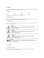
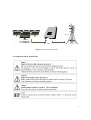
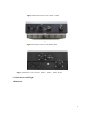
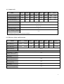
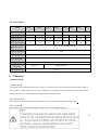
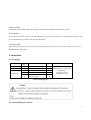
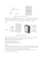
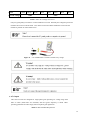
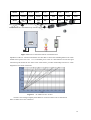
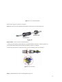
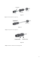
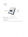
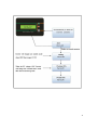
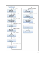
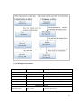
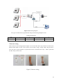
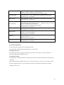
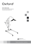
Solar Grid Tie Inverter User Manual 1. Notes This manual is an integral part of the inverter. Please read this manual carefully before installation, operation or maintenance and it’s for future reference. 1.1 Scope 1KTS 1.5KTS 2KTS 3KTS 4KTS 5KTS 6KTS 7KTS Please keep this manual where it will be accessible at all times. 1.2 Target Group This manual is to be read by qualified installer and PV system user. The tasks described in this manual must only be performed by qualified technical service personnel. 1.3 Symbols Used Some symbols are used in this manual in order to ensure safety of personal and property. Please read the following symbols carefully. 2. Safety 2.1 Appropriate Usage The Series is a Solar PV inverter which converts the DC current from a PV generator into AC current and feeds it into the public grid. 1 Figure 1 Solar PV Grid-tied System 2.2 Important Safety Instructions 2 2.3 Explanation of Symbols This section gives an explanation of all the symbols shown on the inverter and on the type label. ●Symbols on the Inverter ● Symbols on the Type Label ● Important Safety Instructions When using the product, please read follow information below to avoid fire, lightning or other personal injury: 3 ● Before using the Series inverter, read all instructions and cautionary markings on the Series inverter, and all appropriate sections of this guide. ●Use only a accesories recommended or sold by , otherwise may result in risk of fire, electric shock, or injury to persons. ● To avoid risk of fire and electric shock, make sure that existing wiring is in good condition and cables used are not undersized. Do not operate the Series inverter with damaged or substandard wiring. ● Do not disassemble the Series inverter. It contains no user-serviceable parts. See Warranty for instructions on obtaining service. Attempting to service the Series inverter, the user may result in risk of electric shock or fire and will void the warranty. ● To reduce the risk of electric shock, authorized service personnel must disconnect both AC and DC power from the Series inverter before attempting any maintenance or cleaning or working on any circuits connected to the Series inverter. Turning off controls alone will not reduce this risk. ● Keep away from flammable, explosive materials to avoid fire disaster. ● The installation location should not be close to humid or corrosive substance. ● To avoid electric shock, please do not disassemble the inverter as there are high-voltage capacitances installed inside the inverter. Fatal High-voltage will remain in the inverter for 5 minutes after its disconnection from grid or PV plant. ● To reduce the chance of short-circuits, authorized service personnel must use insulated tools when installing or working with this equipment. 3.Introduction 3.1 Basic Features Congratulations on your purchase of a series inverter. The Series inverter is one of the finest inverter on the market today, incorporating state-of-the-art technology, high reliability, and convenient control features. Advanced MCU ( Microcontroller Unit) control technology. Utilize the latest high-efficiency power component. Optimal MPPT technology. Advanced anti-islanding solutions. 4 Excellent protections. IP65 protection level. Efficiency up to 97.6%. Total Harmonic Distortion (THD)<3%. Safe & Reliable: transformer less design with software and hardware protection. Friendly HMI ( Human Machine Interface). LED status indication. LCD display of technical data, Human-Machine interaction through press key. RS485/RS232 communication interface. PC remote control. 3.2 Electrical block diagram Figure 2 Electrical block diagram ●Terminals on the inverter 5 Figure 3 Terminals of PV inverters 1KTS/ 1.5KTS t Figure 4 Terminals of PV inverters 2KTS/ 3KTS Figure 5 Terminals of PV inverters 4KTS / 5KTS / 6KTS/ 7KTS 3.3 Dimensions and Weight ●Dimension 6 Figure 6 1KTS/ 1.5KTS Figure 7 2KTS/ 3KTS 7 Figure 8 4KTS / 5KTS / 6KTS/ 7KTS ●Weight Table 1 Weight in kilo grams, kgs Model Weight [kgs] 1KTS 1.5KTS 11Kgs 2KTS 11.5Kgs 3KTS 15Kgs 4KTS 15.5Kgs 21Kgs 5KTS 6KTS 7KTS 21.5Kgs 22.5Kgs 23Kgs 4. Technical Data 4.1 Input (DC) Model Max. DC power [W] 1KTS 1.5KTS 1100 1600 Max. DC voltage [V] Max. input Current [A] Number of MPP trackers / Strings per MPP tracker MPPT voltage range (at rated power) [V] Shutdown voltage / Start voltage [V] 2KTS 2300 3KTS 3200 4KTS 4200 5KTS 5400 500 8.8 9.7 6KTS 160-425 70 / 100 6100 7000 32 37 550 11 13 21 26 1/1 120-425 7KTS 200–500 1/2 210-500 180-500 180-500 180-500 180-500 70/100 8 4.2 Output (AC) 1KTS Model 1.5KTS 2KTS 3KTS 4KTS 5KTS AC nominal power [W] 1000 1500 2000 2600 3000 3680 Max. AC power [W] 1000 1500 2200 2800 3300 3680 Max. AC current [A] 4.5 6.8 9 13.6 17.5 Nominal AC voltage / range [V] 230 / 180~270 AC grid frequency / range [Hz] 50 / 47~52 6KTS 4000 7KTS 4600 4400 5000 23 27 32 5KTS 6KTS 1 Power factor (cosφ) Total harmonic distortion (THD) (at nominal power) <3% *Detailed parameter please see local grid standard 4.3 Efficiency, Safety and Protection Model 1KTS 1.5KTS 2KTS 3KTS 4KTS 7KTS Max. efficiency 96.6% 96.8% 96.8% 97.0% 97.4% 97.6% 97.6% 97.6% Euro- efficiency 95.5% 96.0% 96.2% 96.3% 96.5% 97.1% 97.1% 96.8% MPPT efficiency 99.9% Safety & Protection Overvoltage / undervoltage protection Yes DC isolation impedance monitoring Yes Ground fault protection Yes Grid monitoring Ground fault current monitoring Yes DC injection monitoring Yes Yes 9 4.4 General Data Model Dimension (W/H/D) Weight [kg] Cooling concept Noise (typical) [dB] 1KTS 1.5KTS 288*350*140[mm] 11 11.5 Convection 2KTS 3KTS 4KTS 338*430*138[mm] 13.5 <28 Operating temperature range [°C] <30 15.5 <30 2 1 Fan 21.5 22 Fan Fan 2 3 Fan <30 <40 <40 <40 IP65 Topology Transformer less Internal consumption( night ) [W] 0 LCD display Standard warranty 7KTS -20 °C ~ +60 (de-rating at 45 °C) Degree of protection Communication interfaces 6KTS 345/440/186[mm] Convection Convection Convection <28 5KTS Backlight, 16*2 character LCD RS232 RS485 / RS232 5 years 5. Function Operation Mode 【standby Mode】 The standby mode means that the inverter is ready for operation but still not connected to the grid. In this mode, it will continue to check whether PV array has enough power to feedback into grid. When the inverter passes dump load test after startup, it will change from standby mode to Checking mode. 【Checking Mode】 If inverter passes dump load test and no error/fault occurs, will start checking mode to deliver power. 【On-grid Mode】 In this mode, series inverters convert PV array’s DC into AC and feedback into grid. 10 【MPPT Mode】 The default setting is MPPT mode, the operation mode will return to MPPT after DC&AC restart. 【Fault Mode】 If any fault/error occurs, inverter will stop delivering power until the fault/error is rectified. Some fault/error will recover automatically, and others may need manual restart. 【Setting Mode】 Press “Function” key for 5 seconds to get into the Setting mode if DC power exists. Please refer to chapter 7 of the Manual more information. 6. Installation 6.1 Packaging Type Equipment Accessories Accessories Project No. 1 2 3 4 5 6 Description PV Grid-tied Inverter Backboard Spare parts AC connector DC connector assembly Product manual QTY Remark 1 unit 1 pc 1 bag 1 pc 1/2 1 pc Spare parts bag includes M5 flange nuts, expansion screws, M5 tapping screws Table 1 Packaging list 6.2 Preinstallation precautions 11 Check the location where inverter is to be installed to ensure the following. ●The ambient temperature is within the operation range ( -20°C to +60°C -4°F to +140°F,). ●The altitude is less than 2,000 m. ● Not prone to be damaged by sea water. ● Not close to corrosive gas or liquid (for example, locations where chemicals are processed or lots of poultry is fed). ● Not exposed to direct sunlight. ● Not prone to be flooded snowed in. ●Ensure good ventilation and low humidity. ● Not exposed to steam, vapor, or water. ●Not exposed to direct cool air. ●Not close to television antenna or antenna cae. ●Inverter needs to be at least 30 cm (see table 2) clearance. If this is not observed, inverter is likely to malfunction high temperature inside the inverter, will not cover any damage due to this condition . Position Side Top Bottom Front Min. clearance 30cm 30cm 30cm 10cm Table 2 Minimum clearance needed 6.3 Preparation Following tools are needed for installation. Installation Tools Installation Tools: Crimping tool, Plier, Electrical drill and Screwdrivers & adjustable spanner. 6.4 Installation Steps 12 Step 1: Drill holes in the wall with electrical drill according to the size of bracket (it is packed in the box). Drill straight into the wall do not shake the dril to avoid damage to the wall. Depth of the holes should be about 30mm and should be the same in all the holes. After removing dust from the holes, measure the net depth of the holes. If the depth is more than 33mm or less than 27mm, the expansion pipes can not be properly installed. 13 Figure 9 Installation of Expansion Pipe Step 2: Clean all dust outside/inside the hole and ensure the distances between hole are as per requirement. Insert expansion pipes into the holes vertically, use rubber hammer to tap the pipes into the wall completely. Insert the bracket into expansion pipes and use expansion screws to fasten the Bracket. Figure 10 Bracket Installation Step 3: Mount inverter onto the narrow vertical panel , ensure upper corner of the inverter is hooked onto the bracket, use M5 screws to fix the lower part of the inverter to the bracket (See figure 10). Step 4: Use M5 flange nut to fix the bottom of the inverter. Step 5: Complete the installation process. 6.5 Connections of the PV power system ●PV String inverters 4KTS, 5KTS 6KTS and 7KTS have facility to connect two strings of PV modules while the other models can only take one module string. Use only one string PV modules with excellent performance and reliable quality. Open-circuit voltage of modules connected in series should be < Max. DC input voltage of the inverters (Ref Table 3) and the operating voltage at all times should be within the MPPT voltage range. 14 Model Max. DC voltage 1KTS 1.5KTS 2KTS 500V 3KTS 4KTS 5KTS 6KTS 7KTS 550 V Table 3 Max. DC Voltage of inverters Only use good quality PV cables to connect modules to inverter. Normally the voltage drop between modules and inverter could be about 1-2%. Hence inverter should be installed as close to the PV module as possible to reduce cable losses. Figure 11 Use of Multimeter to measure module array voltage ● AC Output This series inverters are designed for single phase grid. Operating AC voltage range from 180V to 260V (200V-270V for Australia) and the typical frequency is 50Hz. Other operating parameters should comply with local public grid regulations. Table 4 Cable and MCB Requirement 15 Model Cable (Cu) MCB 1KTS 1.5KTS 1.5mm2 2.5mm2 10A 16A 2KTS 2.5mm 2 16A 3KTS 4KTS 4mm2 4mm2 20A 20A 5KTS 6mm 2 32A 6KTS 7KTS 6mm2 40A 6mm2 50A MCB with rated fault current of 30 mA≤Ifn≤300 mA should be installed between inverter and grid. No load should be connected directly with the output of inverter. Figure 12 Incorrect connections between Load and Inverter Impedance of the AC connection should be less than 2Ω. To ensure anti-islanding function PV cable should ensure power loss to be <1% of nominal power. Also AC cable between inverter and grid connection point should be less than 150m. Chart below provides relationship between AC cable length and cross section with losses Figure 13 AC Cable Loss for inverter inverters come with good quality IP66 /IP68 AC connector. Please refer to information below to make correct AC connection. 16 Figure 14 AC Connector details Follow below steps for wiring AC Connectors. Step1: Pass the AC wire through the threaded sleeve and pressure screw (See figure 15). Figure 15 Step2:Connect the AC cables as explained below. · Fix the green and yellow ground cable to the ground terminator in the AC Connector (Figure 16). ·Fix the blue Neutral cable to the N(Neutral) terminator in the AC Connector. ·Fix the Line cable (brown or black wire) to the L(Line) terminator in the AC Connector. Figure 16 AC Connector Step3: Confirm that all the wires are fixed tightly( Figure 17). 17 Figure 17 Step4: Fix the threaded sleeve (Figure 18). Figure 18 Step5: Fix the pressure screw (Figure 19). Figure 19 Step 6: Connect AC connector to inverter (Figure 20). 18 Figure 20 6.6 Inverter Start-up Only start inverter after checking following. a. Make sure all the DC and AC breakers and Isolators are in off position b. AC cable from inverter to connection point is done correct. c. All PV panels are connected to inverter correctly, unused DC connectors should be sealed using covers provided. Starting inverter. a. Turn ON AC MCB b. Turn ON DC Isolator and then AC Isolator b. Inverter will start up automatically when PV arrays generates enough energy. Inverter goes through the following three stages during normal start-up. Waiting: Inverter is waiting / checking PV arrays output DC voltage to be with adequate. At this time DC voltage is with in range of DC100V-DC150V. Checking: Inverter checks AC grid conditions automatically when DC input voltage exceeds Startup voltage. Inverter then goes through the start-up count down. Normal: Inverter begins to operate normally with green light ON and feed power to grid, LCD displays present output power. Inverter will stop feeding power to grid when PV output is not enough for normal operation. 19 7. Operation 7.1 Control Panel Figure 21 Control Panel Normal (green):The inverter is working in normal state. Fault (red): The system is in fault state. Function key:To check the operating parameters, for details, see section 7.2. 7.2 Display Function The function key is used to set the LCD. It can alternate between different parameters and languages. 20 21 22 7.3 LCD Display Information Table 5 Display Information Operating State Information Display Description Working Condition Power Off No display DC input voltage<70V, inverter stops working Initialization & Waiting Waiting 70V< DC Input voltage≤150V in standby mode Checking grid Checking Input voltage >150V, checking grid-tied mode Normal State Normal state Inverter is working in grid-tied mode Flash Flash Upgrading software Checking Parameters Real-time Power Pac=xxxxW Real-time output power 23 Total energy generation Etotal=xxxxkWh Total energy generated Output Voltage Vac=xxx.xV Output voltage Output Frequency Freq.=xx.xHz Output frequency Output Current Iac=xx.xA Output Current PV Input Voltage Vpv= xxxV PV input voltage PV Input Current Idc= xxx A PV input current Fault Information Grounding fault or surge voltage protection Isolation Fault Isolation Fault Leakage Detecting Ground I Fault Leakage current over rating Fault OVR AC Over voltage rating Fault UVR AC Under voltage rating Fault OFR AC Over frequency rating Fault UFR AC Under frequency rating No Utility No Utility No Utility Fan Fault Fan Fault Fan locked or circuit fault PV Over Voltage PV Over Voltage PV voltage ≥ Max.DC voltage Consistent Fault Consistent Fault CPU or other hardware failure Relay Failure Relay Failure Relay between grid and inverters failed DC INJ High DC INJ High DC injection in AC output over rated value. EEPROM Failure EEPROM Failure EEPROM’s data collectionfailure SCI Failure SCI Failure MCU internal communication failure High DC Bus High DC Bus DC bus voltage is higher than the set value DC Sensor Fault DC Sensor Fault Input DC detector failure GFCI Failure GFCI Failure Leakage current detecting circuit failure Grid Fault failure Others Lock Lock Frozen information Reconnect Reconnect Reconnect to grid after relay disconnect Inverter’s Version Ver xx.xx Version information 24 8. Communication and Monitoring 8.1 Communication Interface inverters have communication interface RS485 and /or RS232 depending on model. Output voltage, current, frequency, fault information, etc., can be delivered to a PC or other monitoring equipment via the RS485/RS232. 8.2 Communication types inverters come with one or both of the following types communication facility depending on model. ① RS232 Communication RS232 is a standard communication interface within a distance of 12m. It transmits data between PC and one series inverter (Figure 22). Figure 22 RS232 Communication Diagram Figure 23 RS232 Communication Cable and Interface Table 6 RS232 Pin Definition Pin 1 2 3 4 5 6 7 8 9 Function NC TxD RxD NC Common (GND) NC NC NC NC Only one inverter can be connected with a PC at one time through RS232 port. This facility is generally used for single inverter communication, software update and testing by service person. ② RS485 Communication RS485 allows upto 32 inverters to communicate at the same time by one cable, but the cable length should not be more than 1200m. In order to monitor multiple inverters at the same time, users need to install a monitor system Tress Browser in the PC to browser the PV plants operating data. Tress Browser doesn’t need PC software, pls check the manual of Tress Browser details. Connecting the system as blow (figure 24), user can easily monitoring the PV power station. 25 Figure 24 Monitoring Diagram Two types of cable must be prepared when using for monitoring multipleinverters. RS485 Pin Definition Pin Function 1 2 3 4 TX+ TX- RX+ RX- ③Inverter wiring Find a Ethernet cable with appropriate length. At one end of the cable, strip off about 2 inches of the Ethernet cable sheath. Choose 4 wires (brown, brown white, orange , orange white), and press the 4 wires into pin1 to pin4 of the RJ11 crystal head as below. Then Insert the ready ‐ made crystal head into RS‐ 485 port of inverter. Figure 25 Inverter wiring 26 9. Troubleshooting 9.1 Troubleshooting This section contains information and procedures for solving possible problems on series inverters, and provides troubleshooting tips to identify and solve most problems. This section will help narrow down the source of any problem which you may encounter. Please read the following troubleshooting steps. ●Check the warning or fault messages on the System Control Panel or Fault codes on the inverter information panel. If a message is displayed, record it before doing anything further. ● Attempt the solution indicated in Table 8. ●If the inverter information panel is not displaying a Fault light during a fault condition, check the following to make sure that the installation allows proper operation of the unit. — Is the inverter located in a clean, dry, adequately ventilated place? — Is the DC Isolator in ON position — Are the cables adequately sized and short enough? — Are the input and output connections and wiring in good condition? — Are the configuration settings correct for the particular installation? —Are the display panel and the communications cable properly connected and undamaged? Contact Installer or Customer Service for further assistance. Please be prepared to describe details of of the system installation and also provide the model and serial number of the inverter. Table 8 Troubleshooting tips Faults Grid Fault No Utility Diagnosis and Solutions -Wait for some time to allow grid supply to stabilize for inverter to go back to normal working state. -Making sure that grid voltage and frequency complies with standards. - Seek help from Installer. -No grid supply. - Check grid connection like cables , interface, etc. -Check grid usability. - Seek help from Installer PV Over Voltage -Check the panel’s open-circuit voltage to be less than Max.DC voltage. -If PV open circuit voltage is higher consider rewiring modules to get voltage under limits. DC INJ High - Wait for a minute to see if DC injection returns to normal.. -If fault persists, for assistance. SCI Failure -Disconnect PV +ve and –ve input, and re-connect after a short break. -If fault persists, for assistance 27 Isolation Fault -Check the impedance between PV (+)、PV (-) and ground. For 1.5KW~T2.8KW >1Mohm, 3.3~5KW>2Mohm. - Contact Tress Power if impedance value is not big enough. Consistent Fault -Disconnect PV +ve and –ve input, and re-connect after a short break. -If fault persists, for assistance Relay Failure -Disconnect PV + ve and – ve input, and re-connect after a short break. -If fault persists, for assistance Ground I Fault EEPROM Failure High DC Bus -Leakage current is too high. -Disconnect DC and AC connector, check equipment on the AC side for concerns and rectify any faults found. -Reconnect the DC input and check operation.. -If fault persists, for assistance -Disconnect PV + ve and – ve input, and re-connect after a short break. -If fault persists, for assistance -Disconnect PV + ve and – ve input, and re-connect after a short break. Check AC connection for faults -If fault persists, for assistance fan Fault -Check the fan for any block . -Check fan cables. If fault persists, for assistance GFCI Failure -Disconnect PV + ve and – ve input, and re-connect after a short break. -If fault persists, for assistance 9.2 Routine Maintenance Inverters generally do not have any maintenance needs. The cooling fan is fitted should not be blocked or covered in dust.. ●Cleaning of Inverter Use small electric blower, soft dry cloth or brush to clean inverters. Water, corrosive chemical, or intense cleaning agents should not be used. ●Cooling fin cleaning To ensure proper inverter performance, adequate space needs to be left all around the inverter and heat sink at the back. Fan should not be blocked by dust, snow or any other object. Use air blower, soft cloth or brush to clean cooling fin. Water, corrosive chemicals or intense cleaning agents should not be used for cleaning inverter or fan. 28 10. Decommissioning 10. 1 Dismantling the Inverter ● Disconnect the inverter from DC Input and AC output. ● Remove all connection cables from the inverter. ● Remove the inverter from the bracket. 10. 2 Packaging ●If possible, pack the inverter in the original packaging. ●If original packaging is not available, use an equivalent carton that meets the following requirements. ●Suitable for loads more than 25 kg. ●With handle. ●Can be fully closed. 10. 3 Storage Store the inverter in dry place where ambient temperature is always between -20 °C - +60 °C. 10. 4 Disposal Warranty condition Tress Power will be responbsible for repairing and replacing faulty inverter within 5-year warranty period. 29