1
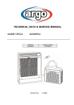
TECHNICAL DATA & SERVICE MANUAL
ARGO 245C / 3SC(I)
Cooling only model
ARGO 235H / 3HP(I)
Heat pump model
0.8180.500.0
05/2007
Table of contents
Page
A SPECIFICATIONS
1) Unit specifications
2) Major Component specifications
3
4
B OPERATING RANGE
5
C DIMENSIONAL DATA
6
D PERFORMANCE CHARTS
7
E REFRIGERANT FLOW DIAGRAMS
10
F FUNCTIONS
1) Cool Mode Operation
2) Heat Mode Operation
3) Auto Mode Operation
4) Dry Mode Operation
5) Fan Mode Operation
6) Auto Fan Speed
7) Forced Mode
8) Protection operations in Cool and Dry Mode
9) Protection operation in Heat Mode
10) I Feel Function
11) Night Function
12) Diagnostic
13) Jumpers
14) Maintenance
15) Manual Unit Control and Led Indicators
16) Outdoor fan operation
17) Drain Pump
11
12
13
14
14
14
15
15
16
18
18
19
20
21
22
23
24
G ELECTRIC WIRING DIAGRAMS
25
H TROUBLESHOOTING
27
I
35
REFRIGERANT CHARGE
L CHECKING ELECTRAL COMPONENTS
1) Measurement of Insulation Resistance
2) Checking Continuity of Fuse on PCS Ass'y
3) Checking Motor Capacitor
36
37
37
M BOILER CONNECTION KIT
1) Specifications and operating limits
2) Performance charts
3) Component specifications
4) Hydraulic connections and valves
38
39
40
41
2
SPECIFICATIONS
A
1) UNIT SPECIFICATIONS
UNIT MODEL
ARGO 245C / 3SC
Power source
PERFORMANCES
Capacity (air
BTU / h
conditioner)
kW
Capacity (hot-water
BTU / h
system)
kW
3
m /h
Air circulation (high/med/low)
Moisture removal (high speed)
Cooling
l/h
Dry
27°C ( 60% R.U.)
liters / 24h
30°C (80% R.U.)
liters / 24h
ELECTRICAL RATINGS
Voltage rating
V
Available voltage range
V
Running Ampere (air conditioner)
A
Running Ampere (hot-water system)
A
Power input (air conditioner)
W
Power input (hot-water system)
W
Power factor
C.O.P
Compressor locked rotor amperes
A
FEATURES
Controls / temperature control
Control unit
Timer
Fan speed (air conditioner)
Fan speed (hot-water system)
Airflow direction
Horizontal
(Indoor)
Vertical
Air filter
Compressor
Refrig./Stand. Charge at shipmen
R410A
Refrigerant control
Sound pressure
Air conditioner Hi/Me/Lo dB(A)
level (Indoor)
Hot-water system Hi/Me/Lo dB(A)
Sound pressure
Air conditioner Hi dB(A)
level (outdoor)
Air conditioner Lo dB(A)
Ducts diameter ( 2pcs )
mm
Water connections diameter onli models 245C / 235H
Condensate drain system
DIMENSIONS AND WEIGHT
Height
mm
Widht
mm
Depht
mm
Holes diameter in the wall (2)
mm
Net weight
kg
ARGO 235H / 3HP
220 - 240 V 50 Hz
COOLING
HEATING
8020
7700
2,35
2,25
7160
2,1
330-300-280
330-300-280
1,2
1,0
--30
30
--59
59
--COOLING
8360
2,45
4,3
935
0,95
2,62
220 - 240
198 - 264
4,2
0,10
900
27
0,93
2,61
17
0,92
2,65
735
839
260-280
162
50 / 48,75
52 / 50,75
Data can be changed without notice
Rating conditions:
outside air temp.: 35° C DB, indoor air temp.: 27° C DB, 19° C WB
outside air temp.: 7° C DB, 6° C WB, indoor air temp.: 20° C DB
3
850
Microprocessor / I.C. Thermostat
Wireless remote control unit
ON / OFF 24 hours and program
3 + Auto
3
Auto (manual for hot water system)
Manual
Washable, easy access
Rotary (hermetic)
520g
600g
Capillary tube
45-43-41
42-39-32
53 at 4 m.
48,5 at 4 m.
162
"
1/2 Gas
Not requested
By duct
NOTE
Cooling:
Heating:
4,0
2) MAJOR COMPONENT SPECIFICATIONS
UNIT MODEL
ARGO 245C / 3SC
CONTROLLER (PCB)
Part No.
Controls
Control circuit fuse (F1)
Jumper Setting JP1….JP5 (see Electric waring diagram)
SWITCH INDICATOR ASSY
Model
Led color
REMOTE CONTROL UNIT
THERMISTOR (COIL SENSOR) TH1
Resistance (at 25° C)
kΩ
THERMISTOR (ROOM SENSOR) TH2
Resistance (at 25° C)
kΩ
THERMISTOR (AIR SENSOR) TH5
Resistance (at 25° C)
Kω
FAN & FAN MOTOR (FMI)
Model
Number / Diameter / Lenght
No. of pole / rpm (230 V, high)
Nominal input
Coil resistance (at 25° C)
mm
W
Ω
Safety device
Setting
°C
Open
Close
µF
VAC
Run capacitor (C2)
FAN & FAN MOTOR (FMO)
Model
Number / Diameter / Lenght
No. of pole / rpm (230 V)
Nominal input
Coil resistance (at 25° C)
mm
W
Ω
Safety device
Setting
°C
Open
Close
µF
VAC
Run capacitor (C3)
COMPRESSOR (CM)
Model
Nominal cooling capacity
Compressor oil RB68A or Freol Alpha68M
Coil resistance (at 20° C)
W
cc
Ω
Ω
µF
VAC
Run capacitor (C1)
Overload relay (OLR)
Operating
Open
temperature
Close
Operating amp. (Ambient temp. 25° C)
°C
°C
4
ARGO 235H / 3HP
SAC ON-OFF IDU
Microprocessor
250VAC - 5A -T
2,54mm - 5 pcs
2,54mm - 5 pcs
PCB
384208021
TMR : blu - STB : yellow - OPR : green
SAC W-REM
NTC (with brass pipe)
10 ± 3%
10 ± 5%
10 ± 5%
K35406-MO2024
Cross-flow 1 / Ø100 / 515
4 / 1350
30
GRY-WHT: 545÷630
WHT-VLT: 92÷105
VLT-ORG: 62÷71
GRY-BRN: 78÷90
(Internal bimetallic type)
150 ± 10K
Autoreset
1,5
440
D2E 146 - HS03 - 46
Centrifugal 1 / Ø146 / 140
2 / 2060
180
BLU-BRN: 74± 5%
BLU-BLK: 66± 5%
(Internal bimetallic type)
150 ± 5K
Autoreset
5
420
Rotary ( Hermetic)
5PS102EAA
2350
350
C-R : 3.863
C-S : 3.309
30
450
External
148 ± 5°C
69 ± 9°C
Trip in 6 to 16 sec. at 16A
UNIT MODEL
ARGO 245C / 3SC
CONDENSATE PUMP (PC)
Model
Rating
Nominal intput
Coil resistance (at 20° C)
SAFETY FLOAT SWITCH (FS)
Model
Contact rating
FLAP MOTOR (FLP)
Type
Model
Rating
Coil resistence (Ambient temp. 25°C)
4 WAYS VALVE (20S)
Model
Coil rating
Coil resistence (Ambient temp. 20°C)
HEAT EXCHANGER COIL (EVAPORATOR)
Coil
Rows
Fin pitch
Face area
HEAT EXCHANGER COIL (CONDENSER)
Coil
Rows
Fin pitch
Face area
THERMOSTATIC VALVE DRAIN PAN
Model
Open
Close
Stroke
B
ARGO 235H / 3HP
291036
220-240VAC~50Hz
5W - 0,05A
778 ± 8%
Ω
BI 1300 2725
230 V AC/DC - 0,5 A
Ω
Ω
Stepping motor
MP24GA1
DC 12V
WHT-BLU (respectively 4 wires) : 380 ± 7%
-------
SQ-136
AC 220V, 50 Hz, 6W
1440 ± 5%
mm
m2
Aluminium plate fin / copper tube
3
1,6
0,107
mm
m2
Aluminium plate fin / copper tube
4
1,3
0,111
---
°C
°C
mm
-------
DP 25-1101-07 or
DP 25-1107
4,4
15,5
5,16
OPERATING RANGE
Cooling only model
Cooling
Dry
Temperature
Maximum
Minimum
Maximum
Minimum
Indoor air intake temp.
32° C DB/ 23° C WB
19° C DB/ 14° C WB
32° C BS/ 80% R.U.
16° C BS/ 80% R.U.
Outdoor air intake temp.
43° C DB
19° C DB
43° C DB
16° C DB
Temperature
Maximum
Minimum
Maximum
Minimum
Maximum
Minimum
Indoor air intake temp.
32° C DB/ 23° C WB
19° C DB/ 14° C WB
27° C DB
//
32° C BS/ 80% R.U.
16° C BS/ 80% R.U.
Outdoor air intake temp.
43° C DB
19° C DB
24° C DB / 18° C WB
-8° C DB / -9° C WB
43° C DB
16° C DB
Heat pump model
Cooling
Heating
Dry
5
All dimensions are in mm
C
DIMENSIONAL DATA
6
PERFORMANCE CHARTS
ARGO 245C / 3SC Cooling only model
Conditions: Power source
Indoor air velocity
230 V - 1- 50 Hz - Single phase
High speed
Cooling characteristics
Indoor relative humidity 48%
W
Capacity (%)
140
130
120
indoor air D.B. temp.
110
DISEGNO
MACCHINA
100
32
27
90
80
19
70
60
19
23
27
31
35
39
43
outdoor air D.B.temp. °C
W
Power input (%)
120
indoor air D.B. temp. °C
115
32
27
110
19
105
100
95
90
85
80
19
23
27
31
35
39
43
outdoor air D.B. temp. °C
E.E.R. (%)
W/W
D
160
indoor air D.B. temp. °C
140
120
100
80
32
27
60
19
40
19
23
27
31
7
35
39
43
outdoor air D.B. temp. °C
ARGO 235H / 3HP Heat pump model
Conditions: Power source
Indoor air velocity
230 V - 1- 50 Hz - Single phase
High speed
Cooling characteristics
Indoor relative humidity 48%
w
Capacity (%)
140
130
120
indoor air D.B. temp. °C
110
100
DISEGNO MACCHINA
32
90
80
27
70
19
60
19
23
27
31
35
39
43
outdoor air D.B.temp. °C
w
Power input (%)
115
indoor air D.B. temp. °C
110
32 27
19
105
100
95
90
85
80
75
19
23
27
31
35
39
43
outdoor air D.B. temp. °C
W/W
E.E.R. (%)
160
140
indoor air D.B. temp. °C
120
100
80
32
27
19
60
40
19
23
27
31
35
39
43
outdoor air D.B. temp. °C
8
Heating characteristics
Outdoor relative humidity 85%
W
Capacity (%)
130
120
indoor air D.B. temp.20°C
110
100
90
DISEGNO
MACCHINA
80
70
60
-10
-6
-2
2
6
10
outdoor air D.B.temp. °C
W
Power input (%)
115
110
indoor air D.B. temp.20°C
105
100
95
90
85
80
75
-10
-6
-2
2
6
10
outdoor air D.B.temp. °C
W/W
COP (%)
160
140
indoor air D.B. temp.20°C
120
100
80
60
40
-10
-6
-2
2
6
10
outdoor air D.B.temp. °C
9
E
REFRIGERANT FLOW DIAGRAM COOLING MODEL
ARGO 245C / 3SC
REFRIGERANT FLOW DIAGRAM HEAT PUMP MODEL
ARGO 235H / 3HP
10
F
FUNCTIONS
1) Cool Mode Operation
In Cooling Mode, the operation of the compressor (CM), Outdoor Fan (FMO) and Indoor Fan (FMI) are
determined by the difference between the room air temperature (RAT) and the set point temperature (SPT)
as shown in the graph.
NOTES
1. In this graph, the FMI is operating with the “Auto Fan Speed” setting. If the user has selected the Low,
Medium or High fan speed, the FMI will run constantly at that speed only.
2. In addition to the temperature difference of above, the operations of the main components (CM, FMO,
FMI) is also controlled by protection delays. That is: - the minimum off time of compressor is 3 minutes. - the minimum off time of compressor is 3 minutes. - the indoor fan can change speed only after it has operated at the same speed for 30 sec if in AUTO
and 1 sec for the other settings (High, Med, Low).
11
2) Heat Mode Operation
The Heating mode operation is similar to the Cooling mode operation. The CM, FMO and FMI are mainly
controlled by the value of (RAT – SPT). In the graph above, the FMI is operating in AUTO speed mode.
Therefore, the FMI speed changes automatically according to the (RT - SPT).
NOTES
1. After the CM has stopped, the FMI runs for 30s in order to purge heat from the indoor coil.
2. The FMI will not be turned on until the indoor coil temperature is warm enough to prevent the supply of
cool air (see COLD DRAFT PREVENTION feature for details).
The indoor fan can change speed only after it has operated at the same speed for 30 sec if in AUTO and
1 sec for the other settings (High, Med, Low).
12
3) Auto Mode Operation
In Auto Mode, the unit switches automatically between the Auto Cooling and Auto Heating in order to
maintain the room temperature (RAT) at the prescribed set point (SPT).
The switching between the two modes is according to the above graph.
Refer to the sections 1.COOLING MODE and 2.HEATING MODE for system operation details.
13
4) Dry Mode Operation
Dry operation remove moisture from indoor air running, in cooling mode, at a low level without
reducing the ambient temperature. This is done cycling ON and OFF indoor and outdoor units
according to below.
ROOM
TEMP
DRY LEVEL
≥ SPT+2°C
LEVEL 0
< SPT+2°C
≥ SPT-1°C
< SPT-1°C
≥ 15°C
< 15°C
Operation according to COOLING mode
CM on
FMO on
FMI switches between L and off (30 seconds)
RV off
CM switches 9 minutes off and 3 minutes on
LEVEL 2
FMO switches 9 minutes off and 3 minutes ON
FMI switches off and L during CM operation
RV off
CM off
DRY OFF ZONE FMO off
FMI off
RV off
LEVEL 1
SPT = Set Point Temperature
5) Fan Mode Operation
With this mode, the indoor fan is turned on while CM, FMO and RV stay off all the time.
The user can select between 3 speeds: HIGH, MEDIUM and LOW.
6) Auto Fan speed
With this option selected, the indoor fan speed changes automatically according to the difference
between the detected air temperature (RAT sensor) and the set point (SPT):
COOLING MODE
2 ≤ (RAT – SPT):
1 ≤ (RAT – SPT) < 2:
(RAT – SPT) < 1:
HIGH speed
MEDIUM speed
LOW speed
HEATING MODE
2 ≤ (SPT - RAT):
(SPT - RAT) < 2:
HIGH speed
MEDIUM speed
NOTE
SPT = Set Point Temperature
14
7) Forced Mode
In this mode the system operates (COOLING or HEATING mode – fixed settings) or is switched off by
means of the OPERATION button on the front panel. The operation modes can be selected
pressing the button in a cyclic way (OFF COOL HEAT OFF…). The settings are:
COOLING mode
SET POINT temperature = 25°C
FAN SPEED = HIGH
HEATING mode
SET POINT temperature = 21°C
FAN SPEED = HIGH
See also paragraph 15 for additional details.
8) Protection operations in Cool and Dry Mode
8.1 Freeze-up
This protection prevents ice formation on the indoor coil heat exchanger. The protection is activated by
the indoor coil temperature (ICT sensor) and only after 6 minutes of compressor operation. This
protection acts in 2 levels:
LEVEL 1
INDOOR FAN SPEED: ANY (as selected from remote controller)
COMPRESSOR: ON
OUTDOOR FAN: cycling (30 seconds ON B 30 seconds OFF).
DRAIN PUMP: operates according to paragraph 17
LEVEL 2
INDOOR FAN SPEED: ANY (as selected from remote controller)
COMPRESSOR: OFF for at least 6 minutes and until ICT ≥ 8°C
OUTDOOR FAN: OFF for at least 6 minutes and until ICT ≥ 8°C
DRAIN PUMP: always ON ( stops when exiting the protection)
The system exit this protection routine when ICT temperature rises above 8°C.
15
9) Protection operations in Heat Mode
9.1 Cold draft
This feature prevents the supply of cold air forcing the indoor fan to a speed which cannot be changed
by the user. As soon as the protection mode is exited speed can be changed manually through the
remote controller. The protection acts in the following
9.2 Defrost
The defrost process is controlled by a detection algorithm designed in order to mantain optimal
utilization of the heat pump capacity especially during negative outdoor temperature conditions.
During DEFROST OPERATION the main components operates according to the following chart:
45 sec.
45 sec
8 sec
8 sec.
16
9.3 Overheat
This feature prevents the build up of high pressure in the indoor heat exchanger during heating
operation
A
B
C
235H
A (°C)
B (°C)
C (°C)
3HP
60
55
46
17
10) I FEEL Function
As standard configuration the air conditioner operates detecting the room temperature through the
sensor equipped in the wireless remote controller (icon I FEEL shown on the display). This feature
provides a personalised environment since the temperature can be detected where the remote
controller is located. It is possible to de-activate this option pressing the I FEEL button on the
remote controller. In this case the I FEEL icon is no longer displayed and room temperature is
detected trough the sensor included in the indoor unit.
11) NIGHT Function
When this function is active, room temperature changes automatically to compensate for body
temperature variations while sleeping. After 10 hours of operation system switches automatically to
OFF state. This mode of operation is available both in COOLING and HEATING mode.
18
12) Diagnostic
With this feature is possible to have a visual signal that a trouble is occurring.
This mode is always active and the signalling is made through the display board LEDS .
In case of no troubles the LEDS status follows its normal function.
NOTES
The troubles are showed according a priority list that is in case of more than one
trouble present, is always showed, at first, the one with the highest priority (1 2 3 etc).
Sensor damaged means a situation where sensor is short-circuited or opened.
In case of damaged sensors, the system (CM, FMO, FMI etc), if in OFF state, does not start.
WRONG MODE SELECTED means a situation where the operating mode chosen with remote controller
does not comply with the one allowed by jumpers settings.
Priority
1
2
3
4
LEDS status
TROUBLE
RAT damaged
ICT damaged
WRONG MODE
SELECTED
Water level alarm
Effects
LD1(stby)
LD2(opr)
LD3(timer)
F
F
F
O
F
F
O
O
F
System does not operate
O
F
O
See paragraph
17. DRAIN PUMP
O = LED off
F = LED blinking
19
13) JUMPERS CONFIGURATION
Jumpers are located on the indoor PCB near the MODE button.
Unit is shipped with jumpers set according to the following table:
JUMPER
JP1
JP2
JP3
JP4
JP5
STATUS
open
open for H/P models - closed for other versions
open
closed
closed
20
14) MAINTENANCE
Changing the Address of the Air Conditioner
In case of more than one air conditioner operating in the same room, it may be necessary to assign an
address to each unit in order to avoid operation conflicts. Address is set acting on the dip-switches located
on the indoor PCB and on the remote controller. The PCB settings must match the corresponding ones
on the wireless remote controller
How to change address of the air conditioner
Dip switch is located on the indoor PCB near the buzzer.
Set the PCB to the address desidered
UNIT
ADDRESS
1
2
3
4
SETTINGS
SW1
SW2
off
off
off
on
on
off
on
on
As default switches SW1 and SW2 are in off status (PCB factory state).
How to change address on Remote Control Unit
Dip switch is located on the battery compartment.
1) Pull out the door and remove the batteries.
2) Set the switch SW1 and SW2 according to the indoor PCB settings
(do not act on SW3 and SW4)
3) Insert the batteries and pull on the door
As default switches SW1 and SW2 are in off status (remote controller factory state).
21
15) Manual Unit Control and LED indicators
The push button switch and the LED indicators on display panel let the user to control the unit
operation without a R/C (Remote Controller). Their operations are provided below.
Push Button Switch :
Use to cycle the operation mode of the A/C unit among COOL, HEAT and
OFF modes, without using the R/C.
OPERATION
BUTTON
Every time this switch is pressed, the next operation mode is selected,
in order:
- Off => Cool mode => Heat mode => Off => … (for heat pump model)
- Off => Cool mode => Off => … (for cooling only model)
- The A/C will start in High fan speed.
The temperature setting is 25°C for cooling and 21°C for heating mode.
WARNING:
the OFF position does not disconnect the power. Use the main power switch to turn off power completely.
Led indicators :
TIMER LAMP
STANDBY
LAMP
1. Lights up during Timer operation.
1. Lights up when the Air conditioner is connected to power and
ready to receive the Remote Control command.
2. Blinks continuously in case of any thermistor failure.
1. Lights up in Operation mode ( Note: OFF in standby mode).
2. Blinks for 0,5 sec., to announce that a R/C infrared signal has
OPERATION
been received and stored.
LAMP
3. Blinks continuously in case of any thermistor failure.
4. Blinks continuously in case of FS (Float Switch) trips for high water level.
TIMER+STBY+OPR LAMP 1. Blinks continuously in case of wrong mode selected.
Recovery from Power Failure
22
16) Outdoor fan operation
Outdoor fan speed change from HI to Low according to outdoor air temperature as indicated on the
chart below.
23
17) DRAIN PUMP
Pump operates when the unit is running in COOLING and DRY modes.
The level detection is done through a float switch connected at the input FS (closed under normal
condition, and opened when water overflow). System operation is according to the following chart:
0sec
10sec
0sec
10sec
24
G
ELECTRIC WIRING DIAGRAMS
1- Cooling only model
ARGO 245C
ARGO 3SC
LEGENDA
PCB
FMI
CM
OLR
FMO
C1-2-3
PC
20S
PCB/FMO
SW-IND-ASSY
TH1-2-3-4-5
TP
HWC
TM
EWV
FS
FLP
F1
Controller
Indoor fan motor
Compressor motor
Overload relay
Outdoor fan motor
Capacitor
Condensate pump motor
4-way valve
Controller Outdoor fan motor
25
Indicator assy
Thermistor
Terminal plate
Hot water control
Limit water thermostat
Water electric valve
Float switch
Flap motor
Fuse
2- Heat pump model
ARGO 235H
ARGO 3HP
LEGENDA
PCB
FMI
CM
OLR
FMO
C1-2-3
PC
20S
PCB/FMO
SW-IND-ASSY
TH1-2-3-4-5
TP
HWC
TM
EWV
FS
FLP
F1
Controller
Indoor fan motor
Compressor motor
Overload relay
Outdoor fan motor
Capacitor
Condensate pump motor
4-way valve
Controller Outdoor fan motor
26
Indicator assy
Thermistor
Terminal plate
Hot water control
Limit water thermostat
Water electric valve
Float switch
Flap motor
Fuse
TROUBLESHOOTING
CHECK BEFORE AND AFTER «TROUBLESHOOTING»
(A) Check power supply wiring.
• Check the power supply wires are correctly connected.
(B) Check power supply.
• Check that voltage is in specified range (±10% of the rating).
• Check that power is being supplied.
• WARNING: If the following troubleshooting must be done with power supplied,
be careful not to touch any uninsulated live part that can cause ELECTRIC SHOCK.
A
CIRCUIT BREAKER TRIPS OR FUSE BLOWS.
• When circuit breaker is set to ON, it trips in a few moments. Resetting is not possible.
• Measure insulation resistance. There is a possibility of ground fault.
If resistance value is 1 Mohm or less, insulation is defective.
B
CIRCUIT BREAKER TRIPS IN SEVERAL MINUTES AFTER TURNING AIR CONDITIONER ON.
1 • There is the possibility of short circuit.
27
2 • The unit does not run.
WATER LEVEL ALARM - OPERATION LAMP IS BLINKING.
Malfunctioning of the condensate drainanege system.
NOTE: In case of emergency the air conditioner can work by drainage the condensate from
the little pipe into a rather short container. Extract the little pipe and remove the cap.
28
D
UNIT AND COMPRESSOR DO NOT RUN.
The unit does not run when air conditioner is in the follwing conditions:
• When the room temperature is below the setting temperature.
• During the protection modes.
29
E
SOME PARTS OF THE AIR CONDITIONER DO NOT OPERATE.
30
F
AIR CONDITIONER OPERATES, BUT ABNORMALITIES ARE OBSERVED.
31
32
G
POOR COOLING OR HEATING.
33
H
EXCESSIVE COOLING OR HEATING.
I
A SENSOR IS DEFECTIVE.
34
I
REFRIGERANT CHARGE
REFRIGERANT CHARGE R410A
ARGO 245C / 3SC
600 g
ARGO 235H /3HP
520 g
IMPORTANT
In order to recharge the unit use the high-pressure side gate.
Preliminary operation after refrigerant charge
DISEGNO
35
DISEGNO MACCHINA
36
DISEGNO MACCHINA
37
M
BOILER CONNECTION KIT ONLY FOR MODELS 245C / 235H
Typical installation
Hot water coil
Existing water
connections
By installer
DISEGNO MACCHINA
1/2" Gas Female
diameter
Electric water
valve
Controller
By installer
Boiler connection Kit
1) SPECIFICATIONS
Power source
Capacity at standard conditions
Power input
Fan speed
Standard conditions:
Water coil only
Valve and tubes
including
OPERATING LIMITS
Max temperature inlet hot water
Max pressure
W
W
Ambient temp.
°C
Fan speed
Inlet water temp. °C
∆T water
K
∆P water
kPa
water flow
l/h
∆P water
kPa
water flow
l/h
°C
bar
38
Air conditioner
unit
230 V ~ 50 Hz
2100
27
3 ( Hi - Me - Lo )
20
High
70
10
0,7 ( 70 mmH2O)
155 ( 2,6 l/min.)
2,9 ( 290 mmH2O)
190 ( 3,1 l/min.)
70°C
10
2) PERFORMANCE CHARTS
Performance on different conditions
10
140%
9
120%
8
70° C inlet water temp.
Pressure drop kPa
Capacity
Capacity ruduction factor : High speed = 1 ; Med. speed = 0,96 ; Low speed = 0,93
7
100%
6
60° C
DISEGNO
MACCHINA
80%
5
4
60%
50° C
3
40%
2
20%
1
0%
0
4
6
8
12
14water temp.)
16
∆t = 10
(inlet water temp.)
- (outlet
Pressure drop kPa
WATER FLOW AND PRESSURE DROP – ( 3 WAY VALVE AND PIPE INCLUDING )
8
7
6
5
4
3
2
1
0
50
100
150
200
250
39
300 Water flow350
l/h
3) COMPONENT SPECIFICATIONS ( Boiler connection kit )
CONTROLLER ( HWC )
Type
Controls
Thermostat
THERMISTOR ( ROOM SENSOR ) TH4
Type
Resistance (at 25° C)
as alternative CONTROLLER ( HWC )
Type
Controls
Thermostat
DISEGNO MACCHINA
THERMISTOR ( ROOM SENSOR ) TH4
Type
Resistance (at 25° C)
LIMIT WATER THERMOSTAT ( TM )
Electrical rating
Control
setting
Differential
WATER ELECTRIC VALVE ( EWV )
Electric Thermal Actuator
Supply voltage
Power consumpion:
Nominal force
Nominal stroke
Full stroke time at 50°C
3-way Forged brass valve
Body Type
Threaded Male Connection
Close-Off Pressure
Water HEAT EXCHANGER COIL
Coil
Rows
Fin pitch
Face area
Threaded Male Connection
Setting
Differential
kΩ
Setting
Differential
kΩ
000TSA
Manual
6°C ±1°C ÷ 30°C ±1°C
1K
STLNGY050
4,7 ±2%
078564-00
Manual
6°C ±1°C ÷ 30°C ±1°C
1K
77798
6,8 ±2%
10(1,6) A - 250Vac
Autoreset
Open : 31°C ±3°C - Close: 42°C±4°C
11K
Type
Continous
Start-up
Actuator stem
Actuator stem
Type
kPa
Type
mm
m2
40
VA-7040-23
230VAC ± 15%
2,5 W
36 W (150 mA) max
125 N
4,5 mm
extends : 60 sec
retract : 10 min
VG-5510EC
3-way NO bypass
1/2" Gas
100
Aluminium plate fin / Copper tube
1
2,0
0,102
1/2" Gas
4) HYDRAULIC CONNECTIONS AND VALVES
DISEGNO MACCHINA
41
DISEGNO MACCHINA
Via Varese, 90 - 21013 Gallarate - Va - Italy
Tel. +39 0331 755111 - Fax +39 0331 776240
www.argoclima.it