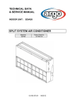
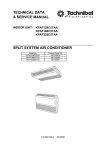
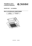
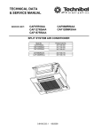
1
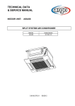
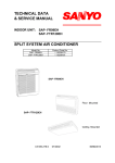
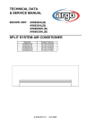
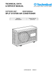
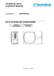
TECHNICAL DATA
& SERVICE MANUAL
INDOOR UNIT:
CWX3B5XAB
CWX5B5XAB
CWX6B5XAB
CWX8B5XAB
CWX10B5XAB
SPLIT SYSTEM AIR CONDITIONER
Model No.
CWX3B5XAB
CWX5B5XAB
CWX6B5XAB
CWX8B5XAB
CWX10B5XAB
Product Code No.
38.7106.000
38.7106.001
38.7106.002
38.7106.003
38.7106.004
0.8180.572.1
April 2011
Table of Contents
Page
1. SPECIFICATIONS
1-1 Unit specifications
1-2 Major Component specifications
1-3 Other Component specifications
3
3
8
13
2. DIMENSIONAL DATA
14
3. ELECTRICAL DATA
3-1 Electric Wiring Diagrams
3-2 Jumpers Configuration
3-3 Contacts for Building Automation
3-4 Maintenance
17
17
19
21
22
4. FUNCTION
4-1 Cool Mode Operation
4-2 Heat Mode Operation
4-3 Auto (cool/heat) Mode Operation
4-4 Dry Mode Operation
4-5 Fan Mode Operation
4-6 Auto Fan Speed
4-7 Forced Mode
4-8 Protection Operation in Heat Mode
4-9 I Feel Function
4-10 Night Function
4-11 Drain Pump Mode
4-12 Diagnostic
23
23
24
25
26
26
26
27
27
29
29
29
30
5. CHECKING ELETRICAL COMPONENTS
5-1 Measurement of Insulation Resistance
5-2 Checking Continuity of Fuse on PCB Ass'y
31
31
32
2
1. SPECIFICATIONS
1-1 Unit Specifications
CWX3B5XAB
230 V - 50 Hz
Power source
Performance
Input
Running Amps
Total cooling capacity (1)
Sensible cooling capacity (1)
Heating capacity (2)
Air circulation
High/Med./Low
High/Med./Low
High/Med./Low
High/Med./Low
Features
Controls/Temperature controls
Control unit
Timer
Fan speed
Airflow direction
Water FLOW in cooling
High/Med./Low
Pressure drop on water in cooling (1) High/Med./Low
Pressure drop on water in heating (2)
High
Air Filter
Power noise level
High/Med./Low
Water tubing connections
Air clean filter
3-Way valve + By-pass (1/2 gas male, KVS 1,6, 230 NC)
Dimensions & Weight
Dimensions
Unit
Ceiling panel
Package dimensions
Unit
Ceiling panel
Weight
Unit
Ceiling panel
kW
A
kW
kW
kW
m³/h
0,052
0,24
2,6/2,35/2,15
2,31/2,09/1,91
3,49/3,11/2,83
520/460/400
l/h
kPa
kPa
Microprocessor/ I.C. thermostat
Wireless remote control unit
ON/OFF 24 hours
3 and Auto
Auto (Remote control)
447/395/360
22,0/18,0/15,0
18
Washable, polypropylene, class HB (UL94)
46/43/40
1/2" gas female
Optional
Optional
dB-A
273
mm
575
mm
575
mm
64
mm
730
mm
730
mm
380
mm
744
mm
650
mm
0,18
m3
110
mm
800
mm
800
mm
3
0,07
m
18,2
kg
22,7
kg
2,50
kg
4,70
kg
DATA SUBJECT TO CHANGE WITHOUT NOTICE
Height
Width
Depth
Height
Width
Depth
Height
Width
Depth
Volume
Height
Width
Depth
Volume
Net
Shipping
Net
Shipping
(1) Air inlet 27°C (D.B.) / 19°C (W.B.); Water inlet 7°C; Water outlet 12°C
(2) Air inlet 20°C; Water inlet 50°C (same water capacity as in conditions (1))
OPERATION LIMITS
Min. water inlet temperature 4°C
Max. water inlet temperature 60°C
Max. operating pressure of hydraulic circuit 16 bar
Min. air recirculation temperature 5°C
Max. air recirculation temperature 32°C
3
CWX5B5XAB
230 V - 50 Hz
Power source
Performance
Input
Running Amps
Total cooling capacity (1)
Sensible cooling capacity (1)
Heating capacity (2)
Air circulation
High/Med./Low
High/Med./Low
High/Med./Low
High/Med./Low
Features
Controls/Temperature controls
Control unit
Timer
Fan speed
Airflow direction
Water capacity in cooling
High/Med./Low
Pressure drop on water in cooling (1) High/Med./Low
Pressure drop on water in heating (2)
High
Air Filter
Power noise level
High/Med./Low
Water tubing connections
Air clean filter
3-Way valve + By-pass (1/2 gas male, KVS 1,6, 230 NC)
Dimensions & Weight
Dimensions
Unit
Ceiling panel
Package dimensions
Unit
Ceiling panel
Weight
Unit
Ceiling panel
kW
A
kW
kW
kW
m³/h
0,087
0,41
4,70/4,10/3,60
3,72/3,21/2,80
5,70/4,85/4,35
750/630/530
l/h
kPa
kPa
Microprocessor/ I.C. thermostat
Wireless remote control unit
ON/OFF 24 hours
3 and Auto
Auto (Remote control)
790/690/600
42/32/25
33
Washable, polypropylene, class HB (UL94)
55/51/48
1/2" gas female
Optional
Optional
dB-A
273
mm
575
mm
575
mm
64
mm
730
mm
730
mm
380
mm
744
mm
650
mm
0,18
m3
110
mm
800
mm
800
mm
3
0,07
m
18,2
kg
22,7
kg
2,50
kg
4,70
kg
DATA SUBJECT TO CHANGE WITHOUT NOTICE
Height
Width
Depth
Height
Width
Depth
Height
Width
Depth
Volume
Height
Width
Depth
Volume
Net
Shipping
Net
Shipping
(1) Air inlet 27°C (D.B.) / 19°C (W.B.); Water inlet 7°C; Water outlet 12°C
(2) Air inlet 20°C; Water inlet 50°C (same water capacity as in conditions (1))
OPERATION LIMITS
Min. water inlet temperature 4°C
Max. water inlet temperature 60°C
Max. operating pressure of hydraulic circuit 16 bar
Min. air recirculation temperature 5°C
Max. air recirculation temperature 32°C
4
CWX6B5XAB
230 V - 50 Hz
Power source
Performance
Input
Running Amps
Total cooling capacity (1)
Sensible cooling capacity (1)
Heating capacity (2)
Air circulation
High/Med./Low
High/Med./Low
High/Med./Low
High/Med./Low
Features
Controls/Temperature controls
Control unit
Timer
Fan speed
Airflow direction
Water capacity in cooling
High/Med./Low
Pressure drop on water in cooling (1)
High/Med./Low
Pressure drop on water in heating (2)
High
Air Filter
Power noise level
High/Med./Low
Water tubing connections
Air clean filter
3-Way valve + By-pass (1/2 gas male, KVS 1,6, 230 NC)
Dimensions & Weight
Dimensions (include panel)
Package dimensions
Unit
Ceiling panel
Weight (include panel)
Ceiling panel
kW
A
kW
kW
kW
m³/h
0,115
0,5
6,0/5,0/4,20
4,70/3,80/3,20
7,70/6,40/5,40
1300/1060/850
l/h
kPa
kPa
Microprocessor/ I.C. thermostat
Wireless remote control unit
ON/OFF 24 hours
3 and Auto
Auto (Remote control)
1030/860/720
30/19/14
30,0
Washable, polypropylene, class HB (UL94)
51/44/40
1/2" gas female
Optional
Optional
dB-A
338
mm
860
mm
860
mm
320
mm
880
mm
840
mm
0,238
m3
110
mm
965
mm
965
mm
0,1
m3
22
kg
26
kg
6
kg
8
kg
DATA SUBJECT TO CHANGE WITHOUT NOTICE
Height
Width
Depth
Height
Width
Depth
Volume
Height
Width
Depth
Volume
Net
Shipping
Net
Shipping
(1) Air inlet 27°C (D.B.) / 19°C (W.B.); Water inlet 7°C; Water outlet 12°C
(2) Air inlet 20°C; Water inlet 50°C (same water capacity as in conditions (1))
OPERATION LIMITS
Min. water inlet temperature 4°C
Max. water inlet temperature 60°C
Max. operating pressure of hydraulic circuit 16 bar
Min. air recirculation temperature 5°C
Max. air recirculation temperature 32°C
5
CWX8B5XAB
230 V - 50 Hz
Power source
Performance
Input
Running Amps
Total cooling capacity (1)
Sensible cooling capacity (1)
Heating capacity (2)
Air circulation
High/Med./Low
High/Med./Low
High/Med./Low
High/Med./Low
Features
Controls/Temperature controls
Control unit
Timer
Fan speed
Airflow direction
Water capacity in cooling
High/Med./Low
Pressure drop on water in cooling (1)
High/Med./Low
Pressure drop on water in heating (2)
High
Air Filter
Power noise level
High/Med./Low
Water tubing connections
Air clean filter
3-Way valve + By-pass (1/2 gas male, KVS 1,6, 230 NC)
Dimensions & Weight
Dimensions (include panel)
Package dimensions
Unit
Ceiling panel
Weight (include panel)
Ceiling panel
kW
A
kW
kW
kW
m³/h
0,120
0,5
8,0/6,50/5,50
6,40/5,40/4,10
9,42/8,52/6,28
1270/1090/830
l/h
kPa
kPa
Microprocessor/ I.C. thermostat
Wireless remote control unit
ON/OFF 24 hours
3 and Auto
Auto (Remote control)
1380/1120/950
41/31/23
39,0
Washable, polypropylene, class HB (UL94)
50/46/37
1/2" gas female
Optional
Optional
dB-A
368
mm
1150
mm
860
mm
350
mm
1170
mm
840
mm
0,35
m3
110
mm
1250
mm
965
mm
0,131
m3
27
kg
32
kg
8
kg
10
kg
DATA SUBJECT TO CHANGE WITHOUT NOTICE
Height
Width
Depth
Height
Width
Depth
Volume
Height
Width
Depth
Volume
Net
Shipping
Net
Shipping
(1) Air inlet 27°C (D.B.) / 19°C (W.B.); Water inlet 7°C; Water outlet 12°C
(2) Air inlet 20°C; Water inlet 50°C (same water capacity as in conditions (1))
OPERATION LIMITS
Min. water inlet temperature 4°C
Max. water inlet temperature 60°C
Max. operating pressure of hydraulic circuit 16 bar
Min. air recirculation temperature 5°C
Max. air recirculation temperature 32°C
6
CWX10B5XAB
230 V - 50 Hz
Power source
Performance
Input
Running Amps
Total cooling capacity (1)
Sensible cooling capacity (1)
Heating capacity (2)
Air circulation
High/Med./Low
High/Med./Low
High/Med./Low
High/Med./Low
Features
Controls/Temperature controls
Control unit
Timer
Fan speed
Airflow direction
Water capacity in cooling
High/Med./Low
Pressure drop on water in cooling (1)
High/Med./Low
Pressure drop on water in heating (2)
High
Air Filter
Power noise level
High/Med./Low
Water tubing connections
Air clean filter
3-Way valve + By-pass (1/2 gas male, KVS 1,6, 230 NC)
Dimensions & Weight
Dimensions (include panel)
Package dimensions
Unit
Ceiling panel
Weight (include panel)
Ceiling panel
kW
A
kW
kW
kW
m³/h
0,180
0,8
9,92/8,09/6,23
7,90/6,22/4,62
11,69/9,53/7,34
2300/1700/1200
l/h
kPa
kPa
Microprocessor/ I.C. thermostat
Wireless remote control unit
ON/OFF 24 hours
3 and Auto
Auto (Remote control)
1700/1400/1070
63/42/26
60,0
Washable, polypropylene, class HB (UL94)
57/49/43
1/2" gas female
Optional
Optional
dB-A
368
mm
1150
mm
860
mm
350
mm
1170
mm
840
mm
0,35
m3
110
mm
1250
mm
965
mm
0,131
m3
27
kg
32
kg
8
kg
10
kg
DATA SUBJECT TO CHANGE WITHOUT NOTICE
Height
Width
Depth
Height
Width
Depth
Volume
Height
Width
Depth
Volume
Net
Shipping
Net
Shipping
(1) Air inlet 27°C (D.B.) / 19°C (W.B.); Water inlet 7°C; Water outlet 12°C
(2) Air inlet 20°C; Water inlet 50°C (same water capacity as in conditions (1))
OPERATION LIMITS
Min. water inlet temperature 4°C
Max. water inlet temperature 60°C
Max. operating pressure of hydraulic circuit 16 bar
Min. air recirculation temperature 5°C
Max. air recirculation temperature 32°C
7
1-2 Major Component Specifications
CWX3B5XAB
Controller PCB
Part No.
Controls
Control circuit fuse
Jumper setting JP1..JP5
SAC ON-OFF IDU
Microprocessor
250 V - 3,15 A
2,54mm-5pcs
SAC W-REM
Remote Control Unit
Fan & Fan Motor
Type
Q'ty ……. Dia. and lenght
Fan motor model…Q'ty
No. of poles…rpm (230 V, High / 2nd / 3rd / Low)
Running Amps
Power input
Coil resistance (Ambient temp. 20 °C )
Safety devices
mm
A
W
Ω
Type
Operating temp. Open
Close
°C
Run capacitor
µF
VAC
Flap Motor
Type
Model
Rating
Coil resistance (Ambient temp. 25 °C )
Ω
Heat Exch. Coil
Coil
Rows
Fin pitch
Face area
Quantity of water
Centrifugal fan
1…. Ø 280 / L 175
K35406 M01971 …1
4… 630 / 570 / 510 / 240
0,16
33
BLU-BRN: 57,5÷66,2
BLU-BLK: 795÷914
BLK-GRY: 70,1÷80,7
GRY-RED: 70,1÷80,7
RED-WHT/YEL: 228÷262
Internal thermal protector
150 ± 10
Automatic
1,5
400
Stepping motor
MP24Z2
DC 12 V
400 ± 7%
Aluminium plate fin / Copper tube
1
1,3
mm
0,272
m2
0,43
l
DATA SUBJECT TO CHANGE WITHOUT NOTICE
8
CWX5B5XAB
Controller PCB
Part No.
Controls
Control circuit fuse
Jumper setting JP1..JP5
SAC ON-OFF IDU
Microprocessor
250 V - 3,15 A
2,54mm-5pcs
SAC W-REM
Remote Control Unit
Fan & Fan Motor
Type
Q'ty ……. Dia. and lenght
Fan motor model…Q'ty
No. Of poles…rpm (230 V, High/Med/Low/LowLow)
Running Amps
Power input
Coil resistance (Ambient temp. 20 °C )
Safety devices
mm
A
W
Ω
Type
Operating temp. Open
Close
°C
°C
µF
VAC
Run capacitor
Flap Motor
Type
Model
Rating
Coil resistance (Ambient temp. 25 °C )
Ω
Heat Exch. Coil
Coil
Rows
Fin pitch
Face area
Quantity of water
Centrifugal fan
1…. Ø 280 / L 175
K35407-MO1972 …1
4… 880/740/660/290
0,27
61
BLU-BRN: 33,9 ÷ 39,1
BLU-BLK: 325 ÷ 374
BLK-GRY: 78,7 ÷ 90,5
GRY-RED: 49,7 ÷ 57,2
RED-WHT/YEL: 155 ÷ 178
Internal thermal protector
150 ± 10
Automatic reclosing
2,0
440
Stepping motor
MP24Z2
DC 12 V
400 ± 7%
Aluminium plate fin / Copper tube
1
1,3
mm
0,272
m2
0,86
l
DATA SUBJECT TO CHANGE WITHOUT NOTICE
9
CWX6B5XAB
Controller PCB
Part No.
Controls
Control circuit fuse
Jumper setting JP1..JP5
SAC ON-OFF IDU
Microprocessor
250 V - 3,15 A
2,54mm-5pcs
SAC W-REM
Remote Control Unit
Fan & Fan Motor
Type
Q'ty ……. Dia. and lenght
Fan motor model…Q'ty
No. Of poles…rpm (230 V, High)
Running Amps
Power input
Coil resistance (Ambient temp. 20 °C )
Safety devices
mm
A
W
Ω
Type
Operating temp. Open
Close
°C
°C
µF
VAC
Run capacitor
Flap Motor
Type
Model
Rating
Coil resistance (Ambient temp. 25 °C )
Ω
Heat Exch. Coil
Coil
Rows
Fin pitch
Face area
Quantity of water
Centrifugal fan
1…. Ø 443
SFG6X-41D6P…1
6 … 470
0,611
31,4
BRN-WHT: 170,3
WHT-VLT: 18,1
VLT-ORG: 43,2
ORG-YEL: 43,2
WHT-PNK: 83,5
YEL-BLK: 60,2
Internal thermal protector
130 ± 8
79 ± 15
4,5
450
Stepping motor
MP24Z2
DC 12 V
400 ± 7%
Aluminium plate fin / Copper tube
2
1,5
mm
0,343
m2
1,00
l
DATA SUBJECT TO CHANGE WITHOUT NOTICE
10
CWX8B5XAB
Controller PCB
Part No.
Controls
Control circuit fuse
Jumper setting JP1..JP5
SAC ON-OFF IDU
Microprocessor
250 V - 3,15 A
2,54mm-5pcs
SAC W-REM
Remote Control Unit
Fan & Fan Motor
Type
Q'ty ……. Dia. and lenght
Fan motor model…Q'ty
No. Of poles…rpm (230 V, High)
Running Amps
Power input
Coil resistance (Ambient temp. 20 °C )
Safety devices
mm
A
W
Ω
Type
Operating temp. Open
Close
°C
°C
µF
VAC
Run capacitor
Flap Motor
Type
Model
Rating
Coil resistance (Ambient temp. 25 °C )
Ω
Heat Exch. Coil
Coil
Rows
Fin pitch
Face area
Quantity of water
Centrifugal fan
1…. Ø 443
SFG6X-81A6P…1
6 … 530
0,765
38
BRN-WHT: 75,1
WHT-VLT: 6,7
VLT-ORG: 20,6
ORG-YEL: 27,4
WHT-PNK: 42,7
YEL-BLK: 58
Internal thermal protector
130 ± 8
79 ± 15
4,5
450
Stepping motor
MP24Z2
DC 12 V
400 ± 7%
Aluminium plate fin / Copper tube
2
1,5
mm
0,556
m2
1,50
l
DATA SUBJECT TO CHANGE WITHOUT NOTICE
11
CWX10B5XAB
Controller PCB
Part No.
Controls
Control circuit fuse
Jumper setting JP1..JP5
SAC ON-OFF IDU
Microprocessor
250 V - 3,15 A
2,54mm-5pcs
SAC W-REM
Remote Control Unit
Fan & Fan Motor
Type
Q'ty ……. Dia. and lenght
Fan motor model…Q'ty
No. Of poles…rpm (230 V, High)
Running Amps
Power input
Coil resistance (Ambient temp. 20 °C )
Safety devices
mm
A
W
Ω
Type
Operating temp. Open
Close
°C
°C
µF
VAC
Run capacitor
Flap Motor
Type
Model
Rating
Coil resistance (Ambient temp. 25 °C )
Ω
Heat Exch. Coil
Coil
Rows
Fin pitch
Face area
Quantity of water
Centrifugal fan
1…. Ø 443
SFG6X-81A6P…1
6 … 530
0,765
38
BRN-WHT: 75,1
WHT-VLT: 6,7
VLT-ORG: 20,6
ORG-YEL: 27,4
WHT-PNK: 42,7
YEL-BLK: 58
Internal thermal protector
130 ± 8
79 ± 15
6
450
Stepping motor
MP24Z2
DC 12 V
400 ± 7%
Aluminium plate fin / Copper tube
2
1,5
mm
0,556
m2
1,50
l
DATA SUBJECT TO CHANGE WITHOUT NOTICE
12
1-3 Other Component Specifications
CWX3B5XAB
CWX5B5XAB
Thermistor ( Coil sensor TH1)
Resistance
Drain pump
Model
Rating
ΚΩ
PC 309564003
220/240V - 50Hz
14W
0,4 l/min
Voltage
Input
Total head capacity
Safety float switch
Model
Contact rating
CWX6B5XAB
10 ± 3%
BI 1300 2725
230V AC/DC - 0,5A
CWX8B5XAB
CWX10B5XAB
Thermistor ( Room sensor )
Resistance
kΩ
NTC-THERMISTOR
10 at 25 °C
Thermistor ( Coil sensor )
Resistance
kΩ
NTC-THERMISTOR
10 at 25 °C
Drain pump
Model
Rating
PJV-1434A
230V
12W
500 mm / 400 cc/min.
Voltage
Input
Total head / capacity
Safety float switch
Model
Contact rating
FS-0218-102
DC 5V - 50W
13
2. DIMENSIONAL DATA
CWX3B5XAB
CWX5B5XAB
14
CWX6B5XAB
5
261
221
292
232
X-view
100
339
7
124
59
124
6
157
48
30
2
12
25
860
500
12
100
776
368
124
7
9
12
2
221
Air intake grille
Air outlet
Refrigerant liquid line [D. 9.52 (In case of 25 type,
use the tube connector.)]
Refrigerant gas line
D. 12.7: 9, 12 type
Drain connection
Power supply entry
For discharge duct
For fresh air intake
9 Suspension bolt mounting
15
12
776
225
8
Panel center
377
X
820 (Ceiling opening)
566 (Suspention bolt pitch)
860
500
124
1
4
820 (Ceiling opening)
757 (Suspention bolt pitch)
308
3
182
CWX8B5XAB
CWX10B5XAB
124
291
232
59
6
292
X-view
100
339
7
5
244
157
124
182
30
338
2
12
25
790
2
8
12
1066
1150
513
9
124
249
16
12
8
180
12
244
776
Panel center
522
500
3
757 (Suspention bolt pitch)
X
1110 (Ceiling opening)
856 (Suspention bolt pitch)
860
48
820 (Ceiling opening)
1
4
124
Air intake grille
Air outlet
Refrigerant liquid line (D.9.52)
Refrigerant gas line (D.19.05)
Drain connection
Power supply entry
For discharge duct
For fresh air intake
9 Suspension bolt mounting
3. ELECTRICAL DATA
3-1 Electric Wiring Diagrams
CWX3B5XAB
CWX5B5XAB
CWX6B5XAB
CWX10B5XAB
17
CWX8B5XAB
18
3-2 JUMPERS CONFIGURATION
Jumpers are located on the indoor PCB near the MODE button.
1 -
Setting JUMPERS
C = Closed
O = Open
2 -
Fonction
A = Available
E = Not available
(when selecting, all leds
blinking)
NOTE: settings different from the factory one must be done by special worker
FACTORY SYSTEM CONFIGURATION:COOLING ONLY WITH VALVE
COOLING ONLY
SYSTEM
FUNCTIONS
19
JUMPERS
SYSTEM CONFIGURATION:COOLING OR HEATING WITH VALVE
COOLING ONLY
SYSTEM
FUNCTIONS
JUMPERS
SYSTEM CONFIGURATION:HEATING ONLY WITH VALVE
COOLING ONLY
SYSTEM
FUNCTIONS
JUMPERS
SYSTEM CONFIGURATION:COOLING WITH VALVE OR HEATING WITH VALVE
COOLING ONLY
SYSTEM
FUNCTIONS
20
JUMPERS
3-3 CONTACTS FOR BUILDING AUTOMATION
3-3.1 INPUT CONTACT (J4 - green)
The status of this input affects system operation according to the following:
Contact OPEN : system does not operate (always OFF) – inputs from wireless remote controller are not processed
Contact CLOSED: system operates in the normal way according to the inputs coming from wireless remote controller
3-3.2 OUTPUT CONTACT (J12)
This connector is directly tied to the contact (normally open) of a power relay which activates every time the following alarm
condition occur:
•
•
RAT damaged
ICT damaged
In this case when alarm happens, on poles 1 and 3 of J12 connector, 220 VAC-50Hz are available.
Max electrical load: 1A- 240VAC
21
3-4 MAINTENANCE
Changing the Address of the Air Conditioner
In case of more than one air conditioner operating in the same room, it may be necessary to assign an address to each
unit in order to avoid operation conflicts. Address is set acting on the dip-switches located on the indoor PCB and on the
remote controller. The PCB settings must match the corresponding ones on the wireless remote controller.
How to change address of the air conditioner
Dip switch is located on the indoor PCB near the buzzer.
Set the PCB to the address desidered
unit
remote control
indoor unit
REMOTE CONTROL
PCB
As default switches SW1 and SW2 are in off status (PCB factory state).
How to change address on Remote Control Unit
Dip switch is located on the battery compartment.
1) Pull out the door and remove the batteries.
2) Set the switch SW1 and SW2 according to the indoor PCB settings
(do not act on SW3 and SW4)
3) Insert the batteries and pull on the door
As default switches SW1 and SW2 are in off status (remote controller factory state).
22
4.FUNCTION
4-1 Cool Mode Operation
VALVE
NOTES
1. In this graph, the FMI is operating with the “Auto Fan Speed” setting. If the user has selected the Low,
Medium or High fan speed, the FMI will run at that speed only.
2. The indoor fan can change speed only after it has operated at the same speed for 30 sec if in AUTO and 1
sec for the other settings (High, Med, Low).
23
4-2 Heat Mode Operation
VALVE
The Heating mode operation is similar to the Cooling mode operation. The VALVE and FMI are mainly
controlled by the value of (RAT – SPT). In the graph above, the FMI is operating in AUTO speed mode.
Therefore, the FMI speed changes automatically according to the (RT - SPT).
NOTES
1. After VALVE is switched off, the FMI runs for 30s in order to purge heat from the indoor coil.
2. The FMI will not be turned on until the indoor coil temperature is warm enough to prevent the supply of
cool air (see COLD DRAFT PREVENTION mode for details). The indoor fan can change speed only after it
has operated at the same speed for 30 sec if in AUTO and 1 sec for the other settings (High, Med, Low).
24
4-3 Auto (cool/heat) Mode Operation
VALVE(COOL)
VALVE(HEAT))
In Auto Mode, the unit switches automatically between the Auto Cooling and Auto Heating in order to
maintain the room temperature (RAT) at the prescribed set point (SPT).
The switching between the two modes is according to the above graph.
Refer to the sections 5.1 COOLING MODE and 5.2 HEATING MODE for system operation details.
25
4-4 Dry Mode Operation
Dry operation remove moisture from indoor air running, in cooling mode, at a low level without reducing the
ambient temperature. This is done cycling ON and OFF indoor and outdoor units according to below.
ROOM
TEMP
DRY LEVEL
≥ SPT+2°C
LEVEL 0
< SPT+2°C
≥ SPT-1°C
< SPT-1°C
≥ 15°C
< 15°C
JP4 OPEN
JP4 CLOSED
Operation according to
Operation according to
COOLING mode
COOLING mode
CM off
FMO on
FMI runs at LOW speed
RV off
CM off
LEVEL 2
FMO switches 3 minutes
on and 9 minutes off
FMI switches LL and L
during FMO operation
RV off
CM off
DRY OFF ZONE FMO off
FMI off
RV off
LEVEL 1
CM off
FMO off
FMI runs at LOW speed
RV off
CM off
FMO off
FMI switches LL and L
(3 MIN. on and 9 OFF)
RV off
CM off
FMO off
FMI off
RV off
SPT = Set Point Temperature
4-5 Fan Mode Operation
With this mode, the indoor fan is turned on while cooling and heating valve stay off all the time. The user can
select between 3 speeds: HIGH, MEDIUM and LOW.
4-6 Auto Fan speed
With this option selected, the indoor fan speed changes automatically according to the difference between
the detected air temperature (RAT sensor) and the set point (SPT):
COOLING MODE
2 ≤ (RAT – SPT):
1 ≤ (RAT – SPT) < 2:
(RAT – SPT) < 1:
HIGH speed
MEDIUM speed
LOW speed
HEATING MODE
2 ≤ (SPT - RAT):
(SPT - RAT) < 2:
HIGH speed
MEDIUM speed
NOTE
SPT = Set Point Temperature
26
4-7 Forced Mode
In this mode the system operates (COOLING or HEATING mode – fixed settings) or is switched off by
means of the MODE button of the indoor unit control board. The operation modes can be selected
pressing the button in a cyclic way (OFF Ö COOL Ö HEAT Ö OFF…). The settings are:
COOLING mode
SET POINT temperature = 25°C
FAN SPEED = HIGH
HEATING mode
SET POINT temperature = 21°C
FAN SPEED = HIGH
4-8 Protection operations in Heat Mode
5-8.1 Cold draft
This feature prevents the supply of cold air forcing the indoor fan to a speed which cannot be changed
by the user. As soon as the protection mode is exited speed can be changed manually through the
remote controller. The protection acts in the following
27
4-8.2 Overheat
This feature prevents the build up of high pressure in the indoor heat exchanger during heating
operation
A
B
VALVE (HEAT)
A (°C)
65
B (°C)
55
VALVE (HEAT)
28
4-9 I FEEL Function
As standard configuration the air conditioner operates detecting the room temperature through the sensor
equipped in the wireless remote controller (icon I FEEL shown on the display). This feature provides a
personalised environment since the temperature can be detected where the remote controller is located.
It is possible to de-activate this option pressing the I FEEL button on the remote controller.
In this case the I FEEL icon is no longer displayed and room temperature is detected through the sensor
included in the indoor unit.
4-10 NIGHT Function
When this function is active, room temperature changes automatically to compensate for body temperature
variations while sleeping. After 10 hours of operation system switches automatically to OFF state.
This mode of operation is available both in COOLING and HEATING mode.
4-11 DRAIN PUMP Mode
This unit is equipped with a drain pump
The level detection is done through a float switch connected at the input WS (closed under normal condition,
and opened when water overflow). System operation is according to the following chart:
Open
Overflow when
THERMO is ON
Overflow when
THERMO is OFF
Overflow when
unit is OFF(standby)
Closed
ON
OPERATION
led
OFF
Blink
CM
FMO
ON
OFF
ON
Thermostat
Drain
pump
OFF
ON
OFF
T < 10 min
29
4-12 Diagnostic
With this feature is possible to have a visual signal that a trouble is occurring.
This mode is always active and the signalling is made through the display board LEDS .
In case of no troubles the LEDS status follows its normal function.
NOTES
The troubles are showed according a priority list that is in case of more than one
trouble present, is always showed, at first, the one with the highest priority (1 2 3 etc).
Sensor damaged means a situation where sensor is short-circuited or opened.
In case of damaged sensors, the system (CM, FMO, FMI etc), if in OFF state, does not start.
Priority
2
3
4
5
LEDS status
TROUBLE
RAT damaged
ICT damaged
WRONG MODE
SELECTED
Water level alarm
Effects
LD1(stby)
LD2(opr)
LD3(timer)
F
F
F
O
F
F
O
O
F
System does not operate
O
F
O
See paragraph
4-9 DRAIN PUMP MODE
O = LED off
z = LED on
F = LED blinking
WARNING: Priority 4 only for COOLING
30
System does not operate
5 CHECKING ELECTRICAL COMPONENTS
5-1 Measurement of Insulation Resistance
The insulation is in good condition if the resistance exceeds 1 MOhm
a) Power Supply Wires
Clamp the earthed wire of the power supply wires
with the lead clip of the insulation resistance tester
and measure the resistance by placing a probe on
either of the power wires (fig.1).
Then measure the resistance between the earthed
wire and the other power wires (fig.1).
b) Unit
Clamp an alluminium plate fin or copper tube with
the lead clip of the insulation resistance tester and
measure the resistance by placing a probe on N terminal,
and then on Lterminal the terminal plate (fig.2)
c) Measurement of Insulation Resistance
for Electrical Parts
Disconnect the lead wires of the disired electric
part from terminal plate, PCB assy, capacitor, etc.
Similary disconnect the connector. Then measure
the insulation resistance (fig.1 to 4).
Refer to electric wiring diagram.
NOTE
If the probe cannot enter the poles because the hole is too narrow
then use a probe with a thinner pin.
31
5-2 Checking Continuity of fuse on PCB assy
Remove PCB assy from electrical component box (fig.5)
Then pull out the fuse from PCB assy
Check continuity of fuse by the multimeter (fig.6)
32
R.D. 28 Reyrieux BP 131 - 01601 Trévoux CEDEX France
Tél. 04.74.00.92.92 - Fax 04.74.00.42.00
R.C.S. Bourg-en-Bresse B 759 200 728