1
SERVICE MANUAL
MODEL
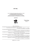
TTM50A-A7
by KANZAKI
Code᧶M2-77623-0020
Service Manual
TTM50A-A7
INTRODUCTION
This manual gives specific instructions for the proper repair on TTM transmissions.
Please follow the procedures carefully to insure quality service.
KANZAKI recommends that you read the manual completely before starting with repairs, as some of the
procedures described are rather complex.
Along with standard tools, KANZAKI recommends the use of special tools, necessary to perform repairs
correctly.
This manual is based on the technical information at the time of printing. The manual has been checked
carefully in order to avoid errors. However KANZAKI is not liable, for any misrepresentations, errors of
description or omissions.
1
Service Manual
TTM50A-A7
CONTENTS
1. To perform Service Safely- - - - - 4
3.4.7. Tapered roller bearings - - - - - 31
1.1. Warning Symbols - - - - - 4
(1) Disassembling the outer races of tapered roller
1.2. Precaution for Safe Servicing - - - - - 5
bearings - - - - - 31
2. General - - - - - 8
(2) Removal of inner races of tapered roller
2.1. Construction - - - - - 8
bearings - - - - - 31
2.2. Specifications - - - - - 8
3.4.8. Clutch pack - - - - - 31
2.3. Power transmission system - - - - - 9
(1) Removal of the clutch disks - - - - - 31
2.4. Hydraulic diagram - - - - - 10
(2) Removal of the clutch pistons - - - - - 32
2.5. Drawing - - - - - 11
3.5. Assembly - - - - - 33
2.6. Sectional View - - - - - 15
Introduction - - - - - 33
3. Overhaul - - - - - 21
3.5.1. Input shaft and support shaft - - - - - 33
3.1. Precautions - - - - - 21
(1) Mount discs into clutch housing - - - - - 33
3.2. Preparing for Overhaul - - - - - 22
(2) Install gears - - - - - 34
3.3. Major components - - - - - 23
(3) Assemble thrust collars - - - - - 34
3.3.1. Transmission set-up - - - - - 23
(4) Re-install tapered roller bearings - - - - - 34
3.3.2. Cleaners and sealants - - - - - 24
(5) Assemble seal rings - - - - - 35
3.3.3. Measuring tools - - - - - 24
3.5.2. Output shaft - - - - - 35
3.3.4. Standard tools and fixture - - - - - 24
(1) If previously removed, re-install tapered roller
3.3.5. Special tools - - - - - 25
bearing - - - - - 35
3.4. Disassembly - - - - - 27
3.5.3. Gear backlash adjustment- - - - - 35
Introduction - - - - - 27
3.5.4. Preassembly of housing - - - - - 36
3.4.1. Oil strainer - - - - - 27
(1) Assembly of outer races - - - - - 36
(1) Draining transmission oil - - - - - 27
(2) Installation of oil suction cover - - - - - 36
(2) Remove oil strainer - - - - - 27
(3) Installation of baffle - - - - - 36
3.4.2. Removal dipstick - - - - - 27
(4) Assemble shaft seal rings - - - - - 37
3.4.3. Output flange - - - - - 23
3.5.5. Measuring the bearing clearance / adjusting the
3.4.4. Oil pump removal - - - - - 23
preload of bearings - - - - - 37
3.4.5. Case plate removal - - - - - 28
(1) General - - - - - 37
3.4.6. Housing - - - - - 29
(2) Bearing clearance adjustment- - - - - 37
(1) Remove the foot - - - - - 29
(3) Inserting gear set into housing - - - - - 38
(2) Remove bell housing - - - - - 29
(4) Re-install outer races of tapered roller bearings
(3) Disassemble the transmission housing
into housing - - - - - 38
halves - - - - - 29
(5) Final assembly of the housing - - - - - 38
(4) Removal of shafts and gears - - - - - 30
3.5.6. Case plate - - - - - 39
(5) Removal of radial shaft seals - - - - - 30
(1) Mounting the case plate - - - - - 39
(6) Removal of baffle and oil suction cover
3.5.7. Oil strainer - - - - - 39
- - - - - 30
(1) Mounting the oil strainer - - - - - 39
2
Service Manual
TTM50A-A7
3.5.8. Output flange - - - - - 39
3.5.9. Making the transmission ready for operation
- - - - - 40
(1) Filling up with SAE30 oil - - - - - 40
(2) Check oil level - - - - - 40
(3) Trial run- - - - - 40
4. Adjustment data - - - - - 41
(1) Shifting pressure - - - - - 41
5. Tightening Torque - - - - - 41
6. Function Test - - - - - 41
7. Recommended Oil - - - - - 43
8. Troubleshooting- - - - -44
3
Service Manual
TTM50A-A7
1. To Perform Service Safely
1.1. Warning Symbols
marked
4
Service Manual
TTM50A-A7
1.2. Precaution for Safe Servicing
5
Service Manual
TTM50A-A7
6
Service Manual
TTM50A-A7
7
Service Manual
TTM50A-A7
2. General
2.1. Construction
This marine gear has a built-in wet type multi-disc clutch and is operated by the oil pressure of the
hydraulic pump. It is composed of the damper, input shaft, reduction gear, clutch, oil pump and the case.
The lube oil for each of the parts is distributed by the oil pump in a forced lubrication system.
When the forward/reverse changing valve lever is moved, oil pressure is applied to move the clutch to the
forward or reverse position.
The clutch for c.w. rotation of O/P is fitted to the input shaft, and the clutch for c.c.w. rotation of O/P is fitted
to the support shaft.
The gear oil(lube oil) is cooled by a multi-pipe seawater cooler.
2.2 Specifications
ITEMS
SPECIFICATION
TYPE
DOWN ANGLE
REMARKS
HYDRAULIC
ANGLE
DEG.
MAX.INPUT TORQUE
8
660
Nᨿm
min-1
INPUT SPEED
700~3800
2.43/2.43
REDUCTION RATIO
2.13/2.13
(F/R)
1.67/1.67
DIRECTION OF ROTATION
I/P
C.C.W
O/P
C.W.
VIEWED FROM STERN
or
C.C.W.
SHIFT
MECHANICAL CABLE
LUBRICATION
FORCED LUBRICATION
OIL QTY.(EFFECTIVE)
DIMENSION
DRY
L
2.0(0.4)
L
mm
250
A
mm
132
W
mm
350
BELL HOUSING SIZE
B/W
CLUTCH SIZE
SAE 111/2”
MARINE GEAR
kg
43
MASS
8
WITH B/W BELL HOUSING
Service Manual
TTM50A-A7
2.3. Power transmission system
ჀPower transmission process at shift lever position A
Damper ൺInput shaft ཱ ൺ Drive gear ི ൺ Input shaft clutch ུ ൺ Input pinion ཱུ
ൺ
Output gear ྲྀ ൺ Output shaft ཷ ൺ Output coupling ླྀ
ჀPower transmission process at shift lever position B
Damper ൺ Input shaft ཱ ൺ Drive gear ི ൺ Driven gear ཱི ൺ Support shaft clutch ཹ
ൺ Support pinion ེ ൺ Output gear ྲྀ ൺ Output shaft ཷ ൺ Output coupling ླྀ
ཱ
ཱུ
ུ
ི
ླྀ
ེ
ྲྀ
ཹ
ཱི
9
ཷ
Service Manual
TTM50A-A7
MECHANICAL SHIFT VERSION
2.4. Hydraulic diagram
ELECTRIC SHIFT VERSION
ዘmark ᧶pressure gauge position (hydraulic/lubrication oil)
10
Service Manual
TTM50A-A7
2.5. Drawing
31
30
29
28
27
26
25
24
23
22
21
20
19
18
17
32
33
37
16
15
39
40
41
42
43
44
45
38
48
14
13
12
11
10
46
9
47
51
52
53
54
55
49
56
57
58
59
60
61
62
63
64
50
8
7
65
66
6
5
67
4
69
68
71
70
3
72
1
2
11
Service Manual
TTM50A-A7
1-Case A
25-Hydraulic Cylinder
49- Cover Suction
2-Oil Seal
26-Drive Gear
50- Baffle Plate
3-Shims(0.3,0.4,0.5,0.8)
27-Input Shaft
51-Seal Ring
4-Bearing
28-Ball
52- Bearing
5-Output Gear
29-Bearing
53- Ball
6-Output Shaft
30-Seal Ring
54- Support Shaft
7-Bearing
31-Shims(0.3,0.4,0.5)
8-Shims(0.2,0.25,0.3,0.35,0.5)
32-Case Plate
56- Hydraulic Cylinder
9-Shims(0.1,0.3,0.5,1.0)
33-Spring Retainer
57- Ring
nd
Relief Seat
10-Bearing
34-2
11-Thrust Collar
35-Spring
12-Ring
58- Ring
59- Spring
36-Spring Pin
nd
55- Driven Gear
60- Spring Retainer
Relief Valve
61- Ring
13-Ring
37-2
14-Friction Disc Retainer
38- Dipstick
62- Thrust Collar
15-Friction Disc
39- Gasket
63- Support Pinion
16-Steel Plate
40- Parallel Pin
64- Bushing
17-Bushimg
41- Bolt
65- Friction Disc
18-Input Pinion
42- Coupling Plate
66- Steel Plate
19-Thrust Collar
43- O-ring
67- Friction Disc
20-Ring
44- Output Coupling
68- Thrust Collar
21-Spring Retainer
45- Oil Seal
69- Ring
22-Return Spring
46- Plug
70- Bearing
23-Ring
47- Case B
71- Ring
24-Ring
48- Name Plate
72- Shims(0.1,0.3,0.5,1.0)
12
Service Manual
TTM50A-A7
8
7
6
5
11
10
4
3
12
2
1
13
9
14
15
30
16
29
28
17
18
27
37
19
20
42
36
35
21
41
40
34
25
39
38
33
26
32
22
23
31
24
13
Service Manual
TTM50A-A7
1-Plug
22-Shifting Lever
2-O-ring
23-Ball Joint
3-Upper Cover
24-Bolt
4-Gasket
25-Switch Support
5-Case Plate
26-Clamp
6-Plug
27-O-ring
7-Gasket
28-Bolt
8-PTO Cover
29-Ball
9-O-ring
30-Seal Ring
10-Hydraulic Pump
31-O-ring
11-Strainer Cover
32-Cover
12-Gasket
33-Modulating Valve
13-Strainer Spring
34-Spring
14-Filter
35-Spring
15-Shifting Valve
36-Shim
16-Pin
37-HO Relief Valve
17-O-ring
38-O-ring
18-Pin
39-Cover
19-Cover
40-Pilot Valve
20-V-ring
41-Throttle Valve
21-Wire Bracket
42-Spring
14
Service Manual
TTM50A-A7
2.6 Sectional View
32
20
27
21
44
26
22
45
18
47
23
46
25
4
19
24
17
34
35
11
10
29
5
28
15 12
11
14
16 25
20
31 30
6
27
26
21
22
38
18
23
40
25
39
19
41
24
17
49
2
7
34
42
33
3
1
37
16
25
30
6
48
13
36
15
8
43
Service Manual
TTM50A-A7
1-Case A
26- Ring
2-Case B
27-Ring
3-Baffle Plate
28-Ring
4-Suction Cover
29-Bearing
5-Shim
30-Bearing
6-Shim
31-Support Shaft
7-Shim
32- Driven Gear
8-Shim
33-Input Pinion
9-Case Plate
34- Bushing
10- Gasket
35-Support Pinion
11- PTO Cover
36-Output Shaft
12-Gasket
37-Output Gear
13- Input Shaft
38-Output Coupling
14- Drive Gear
39-Coupling Plate
15- Ball
40-Bolt
16- Thrust Collar Eng.
41-O-ring
17- Thrust Collar Prop.
42-Bearing
18- Spring Retainer
43-Bearing
19- Friction Disc Retainer
44-Strainer Cover
20- Hydraulic Cylinder
45-Gasket
21- Return Spring
46-Filter
22- Friction Disc
23- Steel Plate
24- Ring
25- Ring
16
Service Manual
TTM50A-A7
(1)
(2)
(4)
(6)
(7)
(3)
(5)
A
(13) (14)
A
Section A-A
(10) (11) (12)
(8) (9)
17
Service Manual
TTM50A-A7
1- Plug
9- Seal Washer
2- Upper Cover
10- Spring Pin
3- Gasket
11- Spring Retainer
4- Plug
12- Spring
5- O-ring
13-2nd Relief Sheet
6- Dipstick with Breather
14-2nd Relief Valve
7- Parallel Pin
8- Magnet Plug
18
Service Manual
TTM50A-A7
(1)
(2)
(3)
(2)
(5)
(4)
(7)
(6)
Mating Surface of Pump
(9) (10) (11)
(13)
(17)
(14)
(8)
(12)
(19)
(16)
Section B-B
C
(18)
(15)
(20)
D
(21)
(29)
Section D-D
B
(30)
(22)
(23)
(24)
(25)
(26)
(27)
(28)
C
Section C-C
D
19
Service Manual
TTM50A-A7
1-Pump
16-O-ring
2-Clamp
17-Cover
3-Wire Bracket
18-O-ring
4-Switch Support
19-Pilot Valve
5-Safety Switch
20-Throttle Valve
6-Ball Joint
21-Spring
7-Shifting Lever
22-Cover
8-Parallel Pin
23-O-ring
9-Spring
24-Modulating Valve
10-Ball
25-Spring
11-Pin
26-Spring
12-O-ring
27-Shim
13-Bolt
28-HO Relief Valve
14-Shifting Valve
29-Cover
15-V-ring
30-Parallel Pin
20
Service Manual
TTM50A-A7
3. Overhaul
3.1. Precautions
21
Service Manual
TTM50A-A7
3.2. Preparing for Overhaul
22
Service Manual
TTM50A-A7
3.3. Major components
3.3.1. transmission set-up
The
main
components
of
the
TTM
Marine
Transmissions are:
Item 1 two-piece aluminum cast
Item 2 gears
1.1 oil strainer
2.1 input shaft with clutch pack assembly for
1.2 oil dipstick & breather
opposite of engine rotation
2.2 support shaft with clutch pack assembly for
same as engine rotation
2.3 output shaft
1.2
2
2.3
2.1
1.1
2.2
Item 3
valves
3.1 rotary valve
3.2 shifting pressure relief valve
3.3 throttle valve
3
3.1
3.2
3.3
1
23
Service Manual
TTM50A-A7
3.3.2. Cleaners and sealants
3.3.4. Standard tools and fixture
For cleaning
Wrench
Cold cleaner such as benzene , trichloroethrane .
For hexagon bolts (8mm, 12mm, 14mm,17mm, 24mm)
Keep detergents away from your skin, do not drink
and do not inhale their vapors! Always wear
protective gloves and safety glasses!
Note accident prevention rules!
Allen wrench (6mm, 8 mm)
For assembly:
ዘ Three bond 1215(or equivalent) for transmission
housing surfaces.
ዘ Grease: Shell Alvania Grease (or equivalent) for
radial shaft seals.
Hexagon socket wrench
3.3.3. Measuring tools
(12mm,13mm,17mm,24mm,30mm)
(6mm, 8mm)
Micrometer
Measuring gauge from 0-25 mm
Accuracy of reading 1/100 mm
Torque wrench
Adjustable up to 450 Nm
Dial indicator gauge with arm-type support
Plastic hammer (1000 g) and sturdy screwdriver
Extractor
Dial gauge increments
Minimum diameter 130 mm
70-80mm
M14-M20
Accuracy of reading:
1/100mm
Dial face can be turned to
zero position
Min ˳130
24
Service Manual
TTM50A-A7
3.3.5. Special tools
SHAFT STAND(Parts No.177524-09240)
BASE (Parts No.177524-09210)
For disassembly of shaft assembly
SPACER B (Parts No.177524-09330)
REPAIR STAND (Parts No.177524-09110)
BEARING EXTRACTOR (Parts No.177523-09350)
For bearing and collar ( eng .side
SPACER A (Parts No.177524-09320)
THRUST COLLAR EXTRACTOR (Parts No.177524-09380)
For collar ( prop .side
SPRING PUSHER (Parts No.177524-09310)
ARM (Parts No.177524-09230)
For disassembly of shaft assembly
25
Service Manual
TTM50A-A7
Wrench (Parts No.177523-09160)
Master-Case B (Output shaft) (Parts No.177524-09550)
for output coupling
for shim adjustment of output shaft assembly
Master-Case A (Parts No.177523-09610)
for shim adjustment of case A
Master-Case A (Input shaft) (Parts No.177523-09510)
for shim adjustment of input shaft and support shaft
assembly
Master-Case A (Output shaft) (Parts No.177524-09520)
Master-Case B (Parts No.177523-09630)
for shim adjustment of output shaft assembly
for shim adjustment of case B
Master-Case B (Input shaft) (Parts No.177523-09560)
for shim adjustment of input shaft assembly
26
Service Manual
TTM50A-A7
3.4. Disassembly
Introduction
Fig.1-2
Clean the transmission thoroughly on the outside before
disassembly.
The repair area should be clean and well lighted.
3.4.1. Oil strainer
(1) Draining transmission oil
Unscrew drain plug (M16) with seal and remove the
oil.(Fig. 1-1 item 1)
2
Drain into clean container for oil inspection.
Check seal for damage. Replace if necessary.
1
(Parts No. 177040-02800)
Fig.1-1
3
3.4.2. Removal dipstick
Extract dipstick (Fig. 2-1, item 1).
Fig.2-1
1
24mm
1
(2) Remove oil strainer
Unscrew three M8x40 bolts (Fig.1-2 item 2) and remove
them together with washers.
Pull cover (Fig.1-2 item 3), seal, strainer element off.
Check seal for damage and strainer for wear. Replace if
necessary.
The oil strainer (Fig.1-2 item 1)must be washed with
clean oil whenever the oil is changed.
27
Service Manual
TTM50A-A7
3.4.3. Output flange
3.4.4. Oil pump removal
Lock output flange in swivel flame.
Unscrew hex head bolts (Fig. 4-1, item1).
Unscrew Hex head bolt (Fig. 3-1, item1)
Remove oil pump (Fig. 4-1, item2)
Remove spacer(Fig.3-2, item1) and O-ring (Fig.3-2
item2)
Fig.4-1
Place extractor on the transmission and pull out the
flange (Fig. 3-3, item1).
Fig.3-1
1
1
2
3.4.5. Case plate removal
Loosen and remove all hex head bolts and lock washers
(Fig. 5-1, item2 and 3).
1
Fig.3-2
Using a plastic hammer lightly tap the split line of the
M1635
case plate surface to break the seal.
2
Pull case plate (Fig. 5-1, item4) and lubricating pressure
relief valve (Fig. 5-1, item5).
Remove locating pins (Fig. 5-1, item 1)
Fig. 5-1
2,3
1
Fig.3-3
4
1
28
5
Service Manual
TTM50A-A7
3.4.6. HOUSING
(1) Remove the foot
Remove the foot (Fig.6-1,item1)
(3) Disassemble the transmission housing
Install the repair stand(Fig.6-1,item2)
halves
Loosen and removal all hex bolts and lock washers (Fig.
6-3, item 2 and 3).
Fig. 6-1
Note the two recessed bolts near input shaft and the four
stainless steel bolts at the housing below(Fig. 6-4).
Lightly tap the housing with plastic hammer. Prying with
1
sharp tools can result in damage to sealing surface,
leakage of oil, and failure of gear.
Remove locating pins (Fig. 6-3, item 1)
Fig. 6-3
2
2,3
(2) Remove bell housing
Remove six M1035 hex head bolts
1
(Figure 4-15,(1))and nuts(Figure 4-15,(2))
with 14mm socket wrench.
2.Remove mounting flange.(Figure4-15,(3))
(The flange is not attached to the model TTM50A -A7)
Fig. 6-4
Fig. 6-2
1
3
2
4 stainless steel bolts
(socket wrench 13mm)
29
Service Manual
TTM50A-A7
(4) Removal of shafts and gears
(5) Removal of radial oil seals
Take the gear set out of the housing.
Input oil seal
ዘ Input shaft (Fig. 6-5, item1).
Discard seal and replace with a new seal (Fig.6-6,
ዘ Support shaft (Fig. 6-5, item2)
item1).
ዘ Output shaft (Fig. 6-5, item3)
1
Fig. 6-6
Check all gears, bearings, piston rings on the input shaft
and support shaft (Fig. 6-5, item 4 and 5) for signs of
wear or failure.
If any of the gears are damaged or showing signs of
excessive wear KANZAKI recommends replacing the
complete gear set.
To check for correct clutch operation, rotate the gears on
the input shaft.
Output oil seal
Inspect clutch for excessive wear, replace clutch as
Discard seal and replace with a new seal(Fig.6-7, item1).
required by feeling of smooth rotating only.
Fig. 6-7
Fig.6-5
1
2
3
1
(6) Removal of baffle and oil suction cover
Take the baffle and the suction cover out of the housing
(Fig.6-8 , item1 and 2).
Keep any dirt out of housing.
1
2
30
Fig. 6-8
Service Manual
TTM50A-A7
3.4.7. Tapered roller bearings
Check for failed bearings or excessive bearing wear.
(1) Disassembling the outer races of tapered
roller bearings
Remove the outer races out of housing halves by
Input shaft and support shaft - propeller side
heating the housing halves in an oven to approx.120ഒ
Do not disassemble the shaft and housing of piston.
If the bearings are damaged, replace the complete
(250 rF):Put the housing in the oven upside down, so
bearing set.
the races will fall out.
3.4.8. Clutch pack
[Notice]
(1) Removal of the clutch disks
ዘHousing can be heated up by using other way ( torch,
Remove retaining ring. ( Fig. 8-1, item1).
heat gun etc)
ዘMake sure to keep the shims with each outer race and
Fig. 8-1
not mix them together.
Use protective gloves when handing the heated
housing and outer races.
Remove Pinion Gear Assembly (Fig. 8-2, item1) .
1
(2) Removal of inner races of tapered roller
bearings
Fig. 8-2
Input shaft and support shaft - engine side
Remove the inner races of tapered roller bearing with
thrust collar by bearing extractor (Fig. 7-1, item1) along
with the arm and threaded rod M16600(Fig.7-1, item2).
Make sure you pull on the thrust collar not on the bearing.
Make sure the direction of thrust collar which is mounted
to the shaft.
Remove retaining ring with pointed object (Fig. 8-3).
Removal pressure plate(Fig. 8-3, item 1).
The discs can now be removed from the housing.
2
Repeat same procedure to remove pressure plate on the
support shaft.
1
Fig. 8-3
1
Fig. 7-1
31
Service Manual
TTM50A-A7
(2) Removal of the clutch pistons
Remove the thrust collar (Fig. 8-4, item1) by the extractor.
Take off retainer ring and spring (Fig. 8-6, item1 and 2).
(Fig. 8-4, item2)
Remove piston(Fig. 8-6 , item3)
Note the direction of thrust collar which is mounted to the
This may require application of low pressure air to
shaft.
opening in end of shaft.
Note the direction of retainer ring which is mounted to the
shaft.
Fig. 8-6
1
(chamfer face up)
Fig. 8-4
2
2
1
3
Compress spring using Spring Pusher, max 5 mm.
compression (Fig 8-5, item 1).
Remove retainer ring.
Fig. 8-5
M16 600
1
32
Service Manual
TTM50A-A7
3.5. Assembly
1
Introduction
2
A well-lighted work area that is free from dirt and debris,
will facilitate the work considerably.
Clean and inspect all parts, install new seals.
Fig. 11-1
Clean housing mating faces.
Cleaners and solvents can be toxic and potentially
harmful without proper ventilation. Use caution
when using such cleaners.
Always wear protective gloves and glasses!
The next assembly procedure requires the following:
ዘ An electric oven or heat gun or heating lamp for
heating the housing halves will be required when
mounting the bearings.
ዘ A hydraulic or mechanical press.
mm(in.)
Stepped wear
3.5.1. Input shaft and support shaft
Fiber disk ᨰ
Standard
Limit
1.65-1.75 (0.065-0.069)
1.55 (0.061)
(1) Mount discs into clutch housing
Install O-rings (2) on piston by lubricating, take care not
Install pressure plate and retainer ring into groove
to stretch O-rings.
making sure ring is seated, chamfer facing up (Fig. 11-2,
Install piston into clutch housing, being careful not to
item 1,2). check for pressure plate alignment and full
damage O-rings. Install return spring and retainer ring,
engagement
pressing down with return spring compression tool.
Locking ring should click into second groove.
Fig. 11-2
Install steel plates and fiber disks(Fig.11-1, item 1,2),
pre-lube all parts, begin and end with steel plate.
Notice : Plate and discs doesn’t have direction ,but the
1
retainer ring should be mounted only one direction that
2
the chamfer surface is up side.
[Notice]
For exact quantity of inner and outer disks, please refer
to the PARTS CATALOG.
33
Service Manual
TTM50A-A7
Repeat same procedure on support shaft.
(2) Install gears
Install clutch gear assembly (Fig. 11-3,item1).
engine side
propeller side
Mount locking ring (Fig. 11-3, item2)
Fig. 11-3
2
1
mm(in.)
Stepped wear
Standard
Limit
engine side ᨰ
4.90-5.00
(0.193-0.197)
4.70
(0.185)
propeller side ᨰ
4.90-5.00
(0.193-0.197)
4.70
(0.185)
Repeat same procedure on support shaft.
(3) Assemble thrust collars
(4) Re-install tapered roller bearings
Heat thrust collars and place onto shaft (120ഒ{250rF})
Heat inner race of tapered bearing (Fig. 11-5, item 1) to
(Fig. 11-4, item1).
approx. 120ഒ(250rF) and push it onto the shaft up
against thrust collar (Fig. 11-5, item 2).
[Notice]
Make sure thrust collars are fully pressed on and have a
clearance of 0.25 to 1.05 mm between thrust collars
Handle heated tapered roller bearing with heat
and top of pinion gear.
resistant gloves!
Thrust collars must not be bent.
[Notice]
Note the direction of thrust collar which is mounted to the
If pressing, be careful not to damage roller cage.
shaft. The thrust collar of engine side must be mounted
Fig. 11-5
lining face-down and the one of propeller side must be
mounted to lining face-up.
1
Lining face
Fig. 11-4
34
Service Manual
TTM50A-A7
(5) Assemble seal rings
Install seal rings (Fig. 11-6, item1) onto input shaft and
3.5.3. Gear backlash adjustment
support shaft.
This procedure is required only when a gear ratio is
Lubricate by grease (common type) for ease installation.
changed.
[Notice]
The shim of propeller side is for adjusting gear backlash.
Fig. 11-6
The shim of engine side is for adjusting bearing side
clearance.
1
A shim here is former one.
Gear backlash must be adjusted as following procedure.
(1) Insert the input shaft assembly in case B with shim
0.9mm behind the outer race of bearing (Fig.13-1,
item1).
(2) Insert the support shaft assembly in case B (Shim is
3.5.2. Output shaft
not needed) (Fig. 13-1, item2)
(1) If previously removed, re-install tapered
(3) Insert the output shaft assembly in case B with shim
roller bearing
0.9mm behind the outer race of bearing (Fig.13-1,
Heat inner race of tapered bearing (Fig. 12-1, item 1 and
item3).
2) to approx. 120ഒ(250rF) and push them onto output
(4)Set the special tool (Fig. 13-2, item1) and insert the
outer race of bearings into individual shafts (Fig.13-2,
shaft up against shaft collar.
item2).
(5)Set the dial gauge on case B and let pick up touch on
input pinion or support pinion. Rotate them lightly and
Handle heated tapered roller bearing with heat
measure the backlash between output gear and input
resistant gloves!
pinion, output gear and support pinion (backlash
standard 0.08-0.16mm) (Fig.13-2).
Fig. 12-1
1
Fig. 13-1
3
2
35
Service Manual
TTM50A-A7
or other way to approx.120ഒ(250rF), or cool outer races
with dry ice or liquid nitrogen.
Insert outer races (Fig. 14-1, item1) into housing.
1
Note: Housing can be heated up by using other way
2
( torch, heat gun etc)
Fig. 13-2
Handle heated tapered roller bearings outer races
only with protective gloves.
Fig. 14-1
1
Dial gauge
If backlash is 0.08-0.16mm, GO TO (6).
ཱ If backlash is under 0.08mm, reduce the shim of the
input shaft.
Whenever reduce the shim by 0.1mm, a backlash
increases by 0.008mm.
(2) Installation of oil suction cover
ི If backlash is over 0.16mm, add the shim of the
Insert suction cover (Fig. 14-2,item 1) into housing.
output shaft
Apply a thin coat of Three bond 1215 (or equivalent) on
Whenever add the shim by 0.1mm, a backlash
housing face.
decreases by 0.008mm
Lock suction cover in place by screwing in bolts (Fig.
Note: the backlash measurement between output gear
14-2 item 2)
and support pinion is only for confirmation because that
Fig. 14-2
value is determined by parts accuracy and can not be
adjusted.
(6) Once take out the output shaft assembly and insert it
again into case B with baffle plate.
3.5.4. Preassembly of housing
(1) Assembly of outer races
(tapered roller bearings)
1
Heat half of the housing (output side of case) in an oven
2
36
Service Manual
TTM50A-A7
assembly is changed.
(3) Installation of baffle
The required preload / play of bearings of the individual
Position baffle plate into housing by aligning tabs.
shafts in the housing is obtained by using shims of
different thickness under the outer races of the roller
bearings.
Shims which have been removed during disassembly
(4) Assemble shaft seal rings
may be reused.
Apply lips of seal rings (Fig. 14-3 and 14-4, item1) with
First adjustment must refer to bearing clearance.
Shell Alvania Grease or equivalent.
Preload/Play (mm)
Grease
0mm
input
support
Output
0.05 preload
ᨺ
0.05 play
0.05 preload
ᨺ
0.05 play
0.20 preload
ᨺ
0.10 preload
(2) Bearing clearance adjustment
Set the special tool (Fig.15-1, item1,2,3 and 4) on case A.
1
Fig. 14-3
ཱMeasure the depth A of individual master (Fig.15-1,
item 5) by dial gauge.
ིSet the special tool (Fig.15-2, item1,2,3 and 4) on case B.
ཱིMeasure the depth B of individual master (Fig.15-2,
Grease
Fig. 14-4
0mm
item 5) by dial gauge.
ུCalculate the thickness T of individual shims by the
following formula. Select and set the thickness of
individual shims based on the below calculation.
1
Input shaft
Tin=Ain+Bins0.05
Support shaft
Tsup=Asup+Bsups0.05
Output shaft
Tout=Aout+Bout+(0-0.1)
1
Fig. 15-1
3 (same as 2)
2
4
3.5.5. Measuring the bearing clearance/
adjusting the preload of bearings
(1) General
This procedure is required when a gear ratio or the shaft
5
37
Service Manual
TTM50A-A7
thickness of shims (Fig. 15-3, item 2).
-
Heat half of the housing (engine side case) in an oven or
A
other way to approx.120ഒ(250rF) or cool outer races with
dry ice or liquid nitrogen.
+
Insert shims and outer races (Fig.15-3, item1) of bearings
into the housing.
When housing has cooled down to ambient temperature,
press outer races carefully down using a copper/brass
punch.
Fig. 15-2
1
1
Fig. 15-3
2
2
4
3 (same as 2)
1
(5) Final assembly of the housing
+
5
ዘ Install baffle (Fig. 15-4, item 1).
ዘ Fill space between seal and dust lips of shaft seal
-
rings with a high quality bearing grease (Shell
-
Alvania Grease or equivalent).
B
ዘ Apply a thin coat of Three bond 1215 (or
B
equivalent)on mating face of housing half (Fig. 15-4,
+
item 2).
ዘ Install locating pins (large chamfer needs to be up)
into housing to align housing halves, before
tightening (Fig. 15-4, item 3).
(3) Inserting gear set into housing
Fig. 15-4
Install the baffle.
4 stainless steel bolts
(socket wrench 13mm)
Clean housing mating face halves with an oilstone.
3
Make sure to keep any dirt out of housing.
(4) Re-install outer races of tapered roller
bearings into housing
2
The bearing clearance measured the preload / play
required in step 3.5.5.(1) will determine the required
1
38
Service Manual
TTM50A-A7
3.5.6. Case plate
3.5.8. Output flange
Remove O-ring before heating flange.
(1) Mounting the case plate
New seal rings have already been assembled according
Heat output flange to 120ഒ (250rF) (Fig.18-1,item1).
to section 3.5.1(5).
Drive flange onto shaft without O-ring using bolt (Fig.18-1,
Remove repair stand, install the foot.
item 4)
Install locating pins (large chamfer needs to be up) (Fig.
Lubricate O-ring (Fig.18-1, item2) with grease and insert
16-1,item 1) into the case plate.
into output flange.
Place lubricating pressure relief (Fig. 16-1,item2) valve
Tighten output flange down on output shaft with bolt (Fig.
on housing.
17-1,item4) and spacer (Fig. 18-1,item3).
Replace gasket (Fig. 16-1 item3) on housing.
Add anti-seize compound to bolt and tighten to torque:
Slide case plate carefully on two shafts.
235-215 Nm
Attach bolts and torque to specifications outlined in
Chapter 5: Tightening Torques.
Fig.18-1
4
Fig. 16-1
1
3
3
2
1
2
1
3.5.7. Oil strainer
(1) Mounting the oil strainer
Check seal for damage and strainer for wear. Replace if
necessary.
The oil strainer(Fig.17-1, item 1)must be washed with
clean oil whenever the oil is changed.
Install strainer, spring, gasket, and cover plate with bolts.
Fig. 17-1
1
(Parts No. 177040-02800)
39
Service Manual
TTM50A-A7
3.5.9. Making the transmission ready for
operation
Fig.19-3
Fig.19-1
OIL
MAX.
(1) Filling up with SAE 30 oil
Filling with SAE 30 oil into the dipstick opening.(Fig.19-1)
Capacity : 2,0 liters. (effective)
MIN.
Type of oil: see chapter 7.
(2) Check oil level
Extract dipstick (Fig. 19-2, item 1).
(1) Wipe dipstick with a dust-free cloth.
(2) Insert dipstick.
(3) Trial run
(3) Remove dipstick and check oil level (Fig. 19-3) : Oil
Carry out a trial run after the oil filling.
level has to be between minimum and maximum
Set shifting lever to neutral position(N). Start engine and
marks.
let it run idle for a short time to fill the cooler and pipelines
with SAE 30 oil.
Fig.19-2
Stop the engine and check oil level again. If necessary,
replenish with oil. Excessive oil should be removed.
1
The oil level on the dipstick (Fig.19-3) should be between
the min. and max. marks .
The oil level should be checked again after a short
running period.
See chapter 6. regarding function test with measuring
instruments required and Tests to be carried out:
40
Service Manual
TTM50A-A7
4. Adjustment data
(1) Shifting pressure
Shifting pressure is hydraulic pressure. Shifting pressure must be between min. and max. line in the below
performance graph at any time. If not so, see troubleshooting in chapter 8.
6KLIWLQJ 3UHVVXUH >0SD
MAX.
MIN.
,QSXW6SHHG>PLQ@
5. Tightening torques
Item
size
Tightening torques
Transmission assembly bolts
M8
18.6-22.6 Nm
M10
37.2-41.2 Nm
M12
65.7-75.5 Nm
M20
215 –235 Nm
Output flange bolt
Dipstick
Hand tight
Breather
Hand tight
6. Function test
When the transmission has been completely assembled and filled up with oil, it would be convenient to make
a function test.
This test can be carried out on a bench test rig, or in a boat.
If no oil cooler can be connected, a hydraulic hose must be connected between the inlet and outlet of the
hydraulic pump.
Measuring instruments required:
ዘ Pressure gauge 0-5 MPa (0 - 750 psi), with connecting thread M10x1.25.
ዘ Temperature gauge 0-120ഒ(0 – 250rF), connecting thread 3/8”-18NPTF.
The position to be mounted the pressure gauge(hydraulic/lubrication oil): see chapter 2.4.(Hydraulic
diagram)
41
Service Manual
TTM50A-A7
Tests to be carried out:
1. Fluid leaks
2. Noise emission
3. Direction of rotation, LH/RH
4. Lube oil temperature
5. Shifting pressure
6. Neutral performance
7. Shifting performance
The function test should be carried out follows:
No.
Motor speed min-1
Shift lever position
Durat.
A: Lever is raised
Test
minutes
B: Lever is lowered
1
800 - 1000
neutral
5
1,2
2
600 - 800 (idling speed)
A<->B position repeatedly
-
1,2,3,6,7
3
1500 - 2500
B position
*
1,2,4
4
600 - 800 (idling speed)
A<->B position repeatedly
-
1,2,3,6,7
5
idling – max. speed
A position
-
1,2,5**
6
600 - 800 (idling speed)
A->B position
-
1,2
7
Idling – max. speed
B position
-
1,2,5**
*Until oil temperature of 75-80ഒ has been reached.
**At different speeds.
Note: see chapter 4(1) Shifting pressure and the below standard value.
Standard value of performance
ITEMS
SPECIFICATION
NEUTRAL PERFORMANCE
(TIME UNTILL SELF-STOPPING)
ᨯ
ู20
REMARKS
Oil temp. 30ഒ
Idling speed
SHIFTING
TIME TO ENGAGE.
ᨯ
ู1.0
Oil temp. 30ഒ
Idling speed
OIL TEMPERATURE
OIL
HO
ഒ
MAX.
MPa
SETTING
MPa
ู90
PRESS.
42
ู4.09
Oil temp. 30ഒ , 3300min-1
3.72s0.05
Oil temp. 60ഒ , 3300min-1
Service Manual
LO
MIN.
MPa
MAX.
MPa
SETTING
MPa
MIN.
MPa
TTM50A-A7
ฺ1.86
Oil temp. 60ഒ , 700min-1
ู0.30
Oil temp. 30ഒ , 3300min-1
0.25s0.05
Oil temp. 60ഒ , 3300min-1
ฺ0.01
Oil temp. 60ഒ , 700min-1
7. Recommended oil
(1) Type of oil
API (American Petroleum Institute) service grade: class CC or CF.
Viscosity: SAE 30
[Notice]
Do not use multi-grade oil and the mixed oils. The single-grade oil must be used.
43
Service Manual
TTM50A-A7
8. Troubleshooting
In case of trouble, check first whether all items of the mounting and operating instructions have been
completed with.
The subsequent tables will assist you troubleshooting.
No. Problem
1
Possible cause
Countermeasure
Transmission cannot be Shifting lever is loose.
Tighten clamping bolt on shifting lever.
shifted.
Remote control does not
Lift remote control off, if gears can be
permit lever travel required for shifted by hand, correct remote
2
Delayed shift time
testing.
control.
Remote control faulty
Repair remote control.
No shifting pressure available
Refer to No.7.
Shift linkage misadjusted; not
Lift remote control off, if gear can be
allowing full engagement.
shifted by hand, correct remote
control.
If the transmission cannot be shifted
correctly by hand, replace the control
block.
3
Clutch is slipping, i.e. Inadmissible oil used.
Drain oil, refill with prescribed oil, flush
propeller speed too low
transmission while engine runs in
as compared to engine
neutral position, drain oil, refill
speed.
transmission.
Oil contains water.
Refer to No.9.
Shifting pressure too low.
Refer to No.6.
Wear on clutch disks.
Disassemble transmission, replace
clutch disks.
4
Piston rings in clutch are
Disassemble transmission, replace
damaged.
clutch.
Transmission locked in Seal ring on input shaft or
Remove case plate, replace seal ring, if
gear
case plate is worn, replace likewise.
support shaft in case plate is
faulty.
Warped disks due to
Refer to No.3.
overheating of slipping
clutch.
Plain bearings on input or
Disassembly transmission, repair if
support shaft are worn out.
possible or use substitute
transmission.
44
Service Manual
No.
5
Problem
Output
shaft
turns
TTM50A-A7
Possible cause
in Rotary valve in casing is
neutral position.
Countermeasure
Replace rotary valve.
worn.
Faulty plain bearing on input
Disassembly transmission and input or
or support shaft.
support shaft, replace bearing
concerned and other damaged parts.
Warped disks due to
Refer to No.3.
overheating of slipping
clutch.
6
Shifting pressure too low
Oil strainer clogged.
Wash strainer or replace fine one.
Oil level in transmission.
Top-up with oil; In case of oil loss check
transmission, cooler and pipelines for
leakage and remedy same; also refer
to No.10 through No.13.
Oil pump is worn out
Replace oil pump.
Spring in shifting pressure
Replace spring.
relief valve is broken.
Seal rings on input shaft or
Remove case plate, replace seal ring, if
support shaft are faulty.
case plate is worn, replace likewise.
Throttle valve for shifting
Replace throttle valve.
pressure is broken.
Piston rings in clutch are
Disassemble transmission , replace
faulty.
clutch.
choke port at modulator valve
Wash the modulator valve.
obstructed by contamination.
7
No
shifting
available
pressure Direction of engine rotation
does not agree with arrow on
Replace with engine of correct of
rotation.
transmission.
No oil in the transmission.
Refill with oil.
Strainer is dirty.
Replace fine strainer.
Oil level in transmission is too Top-up with oil; In case of oil loss check
low.
transmission, cooler and pipelines for
leakage and remedy same; also refer
to No.10 through No.13.
Oil pump is worn out
Replace oil pump.
Spring in shifting pressure
Replace spring.
relief valve is broken.
Throttle valve for shifting
pressure is broken.
45
Replace throttle valve.
Service Manual
TTM50A-A7
No.
Problem
Possible cause
Countermeasure
8
Excessive oil temperature
Excessive oil in transmission
Remove excessive oil with commercial
suction pump.
Oil cooler is dirty on water Clean oil cooler on water side.
side.
Worn oil pump.
Replace oil pump.
Seal rings on input shaft or Remove case plate, replace seal ring, if
support shaft are faulty.
case plate is worn, replace likewise.
Clutch is slipping.
Refer to No.3.
Clutch
does
not
open Dismount transmission and coupling,
completely due to worn disc replace inner disc support and / or
support.
9
clutch.
Water in the oil, oil looks Oil cooler faulty.
Repair leakage at cooler or replace
milky.
cooler.
High water level in engine Remedy cause for water level in engine
compartment, water entering compartment change transmission.
through output shaft seal.
10
Oil
leakage
at
output Breather clogged with paint or Remove paint or dirt from breather.
shaft.
dirt.
Shaft seal faulty.
Disassemble transmission, replace
seal.
If seal location on output shaft is
worn-seal lip should be mounted
offset.
11
Oil leakage at breather.
Excessive oil in transmission
Pump excessive oil out.
12
Oil leakage at joints.
Bolts are not tight.
Tighten bolts with prescribed torque.
Seals on bolts have been
Replace seals, tighten bolts used
several times with prescribed torque.
Mating faces are
Unscrew housing half, finish mating
contaminated, no surface
faces with oilstone or finishing file,
seal applied.
apply surface seal.
Assemble transmission, tighten bolts
with prescribed torque.
46
Service Manual
No.
13
Problem
TTM50A-A7
Possible cause
Transmission
Countermeasure
noise Oil level too low so that pump Top up with oil to marking on dipstick.
becomes louder.
sucks in air.
Damage starting on flexible Replace flexible coupling.
coupling due to misalignment Check alignment between engine and
between engine and
transmission.
transmission.
Beginning damage of
Disassemble transmission, replace
bearings in transmission,
bearings concerned and other faulty
e.g. due to torsional
parts.
vibrations, running without
Find causes and remedy.
oil, overload, wrong
alignment of transmission
excessive engine output.
Beginning damage of
Disassemble transmission, remove
gearings, e.g. due to
faulty parts.
torsional vibrations, running
without oil, overload.
Oil suction cover in
Disassemble transmission, fix oil
transmission has come
suction cover.
loose.
14
Chattering
noise
transmission The engine or propeller
mainly
engine speed.
at
low generate torsional vibrations
in the drive unit which
produce a <<chattering>>
noise in the transmission.
Mount a specified damper between
engine and transmission
(recommended damper᧶Type CF-R136-011-61106-S2 by CENTA. Parts
No.177524-03911).
Otherwise analyze the torsional
vibrations to find out the proper
propeller shaft and propeller (refer to
recommended propeller shaft and
propeller in operation manual).
Misaligned jack shafts on
Mount and align jack shaft strictly
input or output.
according to instructions issued by
jack shaft manufacturer.
47
Service Manual
TTM50A-A7
YANMAR MARINE INTERNATIONAL B.V.
BRUGPLEIN 11 1332 BS ALMERE-DE VAART
THE NETHERLANDS
Tel. 31-36-5493200
Fax 31-36-5493209
48