1
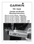
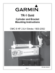
TR-1 Gold
Cylinder and Bracket
Mounting Instructions
Honda 8 HP
1987-2000
906-1060-00
Cylinder Mounting Kit PN 120-1060-00
ITEM
1
2
3
6
7
8
9
10
PART NUMBER
130-0055-00
130-1062-00
130-1064-00
310-0076-25
310-0037-06
310-0200-75
310-0067-02
310-2500-79
QTY
1
1
1
2
2
2
2
1
DESCRIPTION
Carrier, Eye Mounting Bkt.
Bracket, Rod Eye Mounting
Assy., Cylinder Mtg. Angle
Washer Lock
Washer, Ext. Star Lock 5/16 D
Hex Cap 1/4 - 20 X 5/8 (Or 3/4)
Hair Pin Cotter Med.
Clevis Pin 1/4 D X .79
3
9
7
1
2
6
8
10
Cylinder Kit PN 120-0900-00
ITEM
31
33
34
35
36
37
38
40
PART NO.
330-1002-00
310-0042-09
340-0900-00
321-0001-00
330-1101-00
310-0040-26
328-0901-00
328-0902-00
QTY
1
1
1
2
1
1
2
1
NAME
Rod Eye, 5/16-24
Hex Jam Nut 5/16-24
Cylinder
Fitting, Straight 1/8 NPT X 1/4
Zinc Anode (Replace)
Washer, Flat, Nylon 1/4 ID X .03
Bushing 1/4 ID X 5/16 OD X 1/4”L
Cylinder Tail Bushing
35
38
40
34
Tools:
One; Hex Key
(Allen Wrench) 3/32
One; 12mm wrenches
Preferably a socket with
extensions
One; 7/16 In. Wrench
Thread Locker
(Loctite or similar)
Hang Carrier
Tip the motor all the way up. Slide the
Carrier for the Eye Mounting Bracket
(item 1) up between the latch brackets
and over the cross tube that joins them
as shown in figure 4.
Figure 4
Bracket Install
Place the Rod Eye Mounting Bracket
(item 2) as shown in figure 5 against
the face of the Carrier (item 1). Install
the Hex Cap Screws (item 8) and split
Lock Washers (item 6) with some
thread lock through the bracket and
into the carrier and tighten the them.
Figure 5
Tighten Set Screws
Using your 3/32 hex key tighten first the
upper starboard set screw (in the Carrier)
then the lower one.
Figure 6
Remove Shock Cover
Use the 12 MM wrench to remove
the two screws that hold the
lower vibration isolator shroud in
place and remove the shroud. (Be
careful not to loose the rubber
liner.)
Figure 7
Remove Vertical Screws.
Next, use the 12mm wrench to
remove the two port side screws
shown in figure 8.
Figure 8
Mounting The Angle
Replace the washers on the last two screws removed with the star Lock washers (item 7).
Put a little thread lock on the ends of them and install them through the cylinder mounting angle assembly
(item3) and back into the motor as shown in figure 9. (Angle with the label facing you right side up.)
Tighten the screws. Replace the lower vibration isolator shroud removed at figure 7.
A little thread lock should be used on these screws also.
Figure 9
Cylinder Rod Eye
Place the Rod Eye (item 31) over the
vertical pin in the Rod Eye Mounting
Bracket (item 2) as shown. (Leave
the cylinder attached.) Put the plastic
Washer (item 14) on the pin against
the Rod Eye and install the Medium
Hair Pin Cotter (item 9) through the
hole in the vertical pin. Turn the
Cylinder (item 34) Fittings (item 35)
up. The cylinder back end cap mount
should freely align against the top
surface of the mounting ear of the
Cylinder Mounting Angle Assembly
(item 3). If it does not, adjust the set
screws in the Carrier for the Rod Eye
Mounting Bracket (item 1) so that they
do. Be sure the set screws are tight
when you are done.
Figure 11
Cylinder End Cap
Line the hole in rear end cap of
the Cylinder with the hole in the
top of the Cylinder Mounting
Angle Assembly. Slide the Clevis
Pin (item 10) through both hole
from the top. Put the second Hair
Pin Cotter (item 12) through the
cross holes in clevis.
Figure 12
Full Port & Starboard.
Tilt the motor down. Turn the motor hard over to port. That will retract the Cylinder rod into the Cylinder.
Check that the Cylinder rod is still free to retract at least a little more. Next turn the motor hard over to
starboard. That will extend the Cylinder rod out of the Cylinder. Check that the Cylinder rod is still free
to extend at least a little more. It should have additional travel in both directions. If it does not adjust the
position of the Rod Eye (item 31) on the Cylinder shaft. The Cylinder shaft should turn with your fingers if
the Hex Jam Nut (item 32) is loose. (If the shaft does not turn freely enough, use a thin 1/4 Inch open end
wrench at the shaft’s wrench flats.) Do not use any tool on the cylindrical part of the Cylinder shaft.
If the shaft gets scratched, bent, or damaged the seal will fail. With the cylinder properly adjusted, secure
it by tightening the Hex Jam Nut against the Rod Eye. It is ready for plumbing. We suggest you put the
original parts in a container and, carefully, store them. (You may eventually want to sell or trade in your
motor, but we know you will want to keep your TR-1 autopilot.)