1
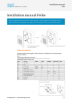
MADE IN SWEDEN
Friction Transporter
Installation & Service Manual
2013-04-12
TPE 30/19 Installation & operation
Oil-change every 5000 hour
250 ml. W75/GLS
Installation instructions
TPE 30 must be mounted horizontally, may not
be mounted on the side or pitched.
A custom tray or chute must be designed. We
recommend aluminum or any light gauge material
to reduce tray weight.
Maximum weight, tray only: 5 kg
Transportation capacity: 30 kg
Using metric screws, fasten tray or chute to the
TPE 30 using all holes. Tray or chute must be
supported at both ends to minimize vibration &
deflection.
Important
TPE 30 must be mounted so no danger is
provided for working personnel.
Operating the TPE 30
Connect the Controller power cable to a power
outlet (110-240 Volt AC, 50/60 Hz).
Do not change or replace the cable between the
transporter and the controller.
Make sure that the tray can move freely in both
directions.
Push the power button on the Controller, the
TPE 30 will start after a few seconds.
If you want to restart the TPE 30 you must wait 5
seconds for the controller to be ready.
CRUSHING HAZARD!
(See arrows in picture)
TPE 30/19 Service
Please note that some parts may not be available
because they are not field replaceable. If this is the
case, a subassembly must be used. Some parts are
only available as a subassembly and cannot be
purchased individually. Check the spare parts
reference lists for details.
Disassembly.
1.
2.
3.
4.
5.
6.
Disconnect the electrical connections.
Drain the oil.
Remove the dome nut 30-276.
Remove the threaded washer 30-157 while holding a screwdriver in the slot on the truss rod 30-147.
Remove the rulers and yoke.
Remove cover 30-111 and disconnect the operation guard and the stator.
Remove the plastic plug to the stator (requires special tools)
7. Loosen the upper screw 30-230.
8. Remove the screws 30-202 (5 pcs).
9. Three of the holes in the motor bracket are threaded M8, use three flat set screws to remove the
motor bracket while the mechanism remains in the lower part.
10. Loosen the lower screw 30-230.
11. Remove the truss rod 30-147.
12. Remove gear 30-143 with a slide hammer and remove the rocker mechanism 30-601.
13. Clean the TPE 30 and remove all silicon residue.
14. To remove the engine cover 30-121: blow compressed air into the hole
where the cables are located.
15. Remove circlip 30-282 to remove the rotor.
N.B. The flywheel 15-139 has a left-handed thread.
Reassembly.
1.
2.
3.
4.
5.
6.
7.
8.
9.
Install the link 30-602 on the rocker mechanism.
Install the connecting rod with bearings on the gear.
Install the connecting rod and gear on the rocker mechanism.
Attach the gear with the connecting rod and rocker mechanism
simultaneously into the machine body.
Turn the rocker mechanism so the distance between the screw head
15-256 and the left indentation edge becomes 43 mm.
Tighten the lower screw 30-230.
Install the truss rod 30-147 on the link 30-602 and glue with Loctite 243.
Place the O-ring 30-351 in the indentation of the cable fitting.
Apply silicon around the indentation edge.
N.B. inside the screw holes location.
10. Mount the motor bracket and fit the motor shaft teeth with the gear,
then tighten the screws.
11. Fit the cover, stand, yoke and rulers.
12. Let the silicon dry overnight.
13. Fill 250 ml. of Oil W 80/90 GL5.
TPE 30/19 Dimensional drawing
TPE 30/19 Spare parts
Part No.
3-325
10-106
10-210
15-139
30-111
30-112
30-121
30-143
30-145
30-146
30-147
30-150
30-155
30-156
30-157
30-158
30-160
30-161
30-162
30-170
30-202
30-221
30-222
Description
O-ring
Bearing
Screw
Fly wheel
Cover
Attachment plate
Motor cover
Gear
Bushing
Sleeve
Truss rod
Guide column
Sleeve
Nut
Threaded washer
Urethane washer
Tray holder
Rear holder
Front holder
Sensor attachment
Screw
Screw
Screw
Qty
2
4
8
1
1
2
1
1
1
1
1
2
1
1
1
2
2
1
1
1
5
7
2
Part No.
30-230
30-245
30-271
30-274
30-276
30-282
30-301
30-307
30-308
30-336
30-351
30-352
30-353
30-361
30-362
30-370
30-420
70-410
100-410
100-411
100-413
100-440
Description
Screw
Screw
Washer
Washer
Dome nut
Snap ring
Bearing
Bearing
Bearing
Bushing
O-ring
O-ring
O-ring
Radial shaft seal
Radial shaft seal
Plug
Socket
Screw
Speed monitor
Socket
Connector
Plint
Qty
2
1
2
3
1
1
1
1
1
1
1
1
1
1
1
1
1
4
1
1
1
1
TPE 30/19 Spare parts
TPE 30/19 Spare parts
30-601 Rocker mechanism
Part No.
10-133
10-407
10-420
15-256
30-124
30-125
30-126
30-127
Description
Ball *
O-ring *
Rivet *
Screw *
Spring *
Eccentric upper *
Eccentric lower *
Eccentric shaft
* Not sold separately
Qty
1
1
1
1
1
1
1
1
Part No.
30-130
30-133
30-235
30-274
30-321
30-322
30-353
40-055
Description
Rocker *
Shaft *
Screw *
Washer
Bushing *
Bushing *
O-ring
Screw
Qty
1
1
1
1
2
1
1
1
30-602 Link
Part No.
30-135
30-136
30-221
Description
Link *
Link shaft *
Screw
* Not sold separately
Qty
1
1
1
Part No. Description
30-271 Washer
30-274 Washer
Qty
1
2
30-603 Connecting rod
Part No. Description
30-132
Connecting rod *
30-306
Bearing *
* Not sold separately
Qty
1
1
Part No. Description
30-336 Bushing
Qty
1
30-604 Retaining pin
Part No. Description
3-325
O-ring
* Not sold separately
Qty
1
Part No. Description
30-128 Retaining pin *
Qty
1
30-610 Motor
Part No.
15-139
30-120
30-121
30-139
30-282
30-308
Description
Fly wheel
Motor house *
Motor cover
Motor shaft *
Snap ring
Bearing
* Not sold separately
Qty
1
1
1
1
1
1
Part No.
30-351
30-362
30-401
30-402
30-604
Description
O-ring
Radial shaft seal
Rotor
Stator
Retaining pin
Qty
1
1
1
1
1
30-611 Motor controller unit
Main cable
1.5 meter
Motor cable
1.5 meter
Technical data
TPE 15/19
Max load capacity
Max tray weight
Stroke length
Feed rate
Sound level
Motor effect
Electrical connection
15 kg
3 kg
19 mm
4-8 m/min
55 dB (A)
0,1 kw
110-240 V
TPE 30/19
Max load capacity
Max tray weight
Stroke length
Feed rate
Sound level
Motor effect
Electrical connection
30 kg
5 kg
19 mm
4-8 m/min
60 dB (A)
0,1 kw
110-240 V
TPE 100
Max load capacity
Max tray weight
Stroke length
Feed rate
Sound level
Motor effect
Electrical connection
100 kg
35 kg
16 mm
8-10 m/min
62 dB (A)
0,5 kw
380-415 V 50-60 Hz.
alternatively 110-120 V
Contact information
Factory repair service.
If your Transporter requires repair, return it prepaid to our Service
Center.
Repairs include fault tracing and repair or replacement of failed
components, as well as final testing to ensure your Transporter
is functioning according to specifications.
All items within the warranty period are evaluated by technicians to verify
warranty eligibility.
All Transporters repaired through Mectool receive a new three
month manufacturer's warranty (wear parts excluded).
Mectool Sweden AB
PJ Rösiös Väg 121-3
293 40 Olofström
Sweden
Phone:
Fax:
Email:
Web:
+46 454 30 90 40
+46 454 416 56
[email protected]
www.mectool.se