1
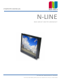
OWNERS MANUAL (Ref. 1013M01V1.4) N-LINE PANEL MOUNT, DESKTOP, REARMOUNT NOTTROT BV, Raamsdonksveer, Nederland For more information please visit www.nottrot.nl or call +31-162-515458 N-LINE OWNERS MANUAL Contents 1 Revision history .......................................................................................................................................................................... 4 2 About this manual ...................................................................................................................................................................... 4 3 Disclaimer ................................................................................................................................................................................... 4 5 Box contents............................................................................................................................................................................... 5 6 Description ................................................................................................................................................................................. 6 7 Product identification................................................................................................................................................................. 6 8 Safety precautions...................................................................................................................................................................... 6 9 Installation.................................................................................................................................................................................. 8 9.1 Mounting the monitor ....................................................................................................................................................... 8 9.1.1 Panel mount .................................................................................................................................................................. 8 9.1.2 VESA mount .................................................................................................................................................................. 9 9.1.3 Rearmount .................................................................................................................................................................... 9 9.2 Connecting the monitor to power and video source ...................................................................................................... 10 9.3 Front controls .................................................................................................................................................................. 10 9.4 Setup for Operation (OSD-menu) .................................................................................................................................... 10 9.5 OSD menu ........................................................................................................................................................................ 12 9.6 Engineering OSD .............................................................................................................................................................. 14 9.7 Projected capacitive touch screen .................................................................................................................................. 15 10 Maintenance ............................................................................................................................................................................ 15 11 Trouble shooting ...................................................................................................................................................................... 16 12 11.1 Power .............................................................................................................................................................................. 16 11.2 Image ............................................................................................................................................................................... 16 11.3 Touch screen ................................................................................................................................................................... 16 Specifications ........................................................................................................................................................................... 17 12.1 Video ............................................................................................................................................................................... 17 12.1.1 Compatibility and video standards ......................................................................................................................... 17 12.1.2 Applicable Graphic Mode ....................................................................................................................................... 17 12.2 Dimensions K, KE, KG and KGE models ............................................................................................................................ 18 12.3 Dimensions D and DE models .......................................................................................................................................... 19 12.4 Dimensions R models ...................................................................................................................................................... 19 12.5 Electrical and environmental ........................................................................................................................................... 20 12.6 Model related specifications ........................................................................................................................................... 21 12.7 Pin assignments ............................................................................................................................................................... 22 13 Pixel policy (ISO 13406-2 Scan Guidelines ) ............................................................................................................................. 24 14 Sticking image .......................................................................................................................................................................... 25 15 Regulatory information ............................................................................................................................................................ 27 16 15.1 CE ..................................................................................................................................................................................... 27 15.2 IEC 60945 ......................................................................................................................................................................... 28 Warranty .................................................................................................................................................................................. 29 16.1 Coverage of the Warranty ............................................................................................................................................... 29 P 2/30 N-LINE OWNERS MANUAL 16.2 Warranty Exclusions and Disclaimer ............................................................................................................................... 29 16.3 Obtaining Warranty Service ............................................................................................................................................ 30 P 3/30 N-LINE OWNERS MANUAL 1 Revision history Before installation or using the monitor make sure you have the latest version of this owners manual. Version Remark 0413M01V1.0 Initial manual 0413M01V1.1 IEC certificate added 0413M01V1.2 Pinning AUX connector modified 0413M01V1.3 Warranty, Viewing angle UD remark 0413M01V1.4 Engineering OSD control added 0143M01V1.5 Pinning external encoder 0143M01V1.6 Pinning external OSD on AUX connector added 2 About this manual The N-Line consists of several models. Since all models are built using the same concept (similar components), all data has been collected to create one manual that describes the entire series. As an option, the N-Line glass version (NxxxKGE) available with IEC60945 certificate. Details are shown as follows: IEC Take special attention when using option IEC60945 certification on your monitor This document contains technical and users information about your monitor. Please make sure you are using the latest version of this manual when installing a new product. Although we strive to be as complete as possible, there will always be additions made. All updates of this document are subject to change without notice. The revision history is shown in chapter 1. 3 Disclaimer Nottrot BV makes no representations or warranties, either expressed or implied, with respect to the contents hereof and specifically disclaims any warranties, merchantability or fitness for any particular purpose. Further, Nottrot BV reserves the right to revise this publication and to make changes from time to time in the contents hereof without obligation of Nottrot BV to notify any person of such revision or changes. Please follow these safety instructions for best performance, and long life for your monitor Copyright © 2013 by Nottrot BV. All rights reserved. No part of this publication may be reproduced, transmitted, transcribed, stored in a retrieval system or translated into any language or computer language, in any form or by any means, electronic, mechanical, magnetic, optical, chemical, manual or otherwise, without the prior written permission of Nottrot BV. P 4/30 N-LINE OWNERS MANUAL 5 Box contents Please check the box contents right after receiving the equipment. The contents depend on the options ordered. Image Description Remark Monitor na External power adapter (230VAC<>12VDC) N.a. with 9~36VDC input option Mains cord (Euro style) Only with external power adapter VGA cable (15p HD-Sub) M/M DVI Cable Optional RS-232 cable Optional touch M/F USB cable Optional touch A/B Touch driver software Optional touch Mounting brackets with M5x50 screws and M5 nuts Panel mount model only Mounting brackets with M4 screw Rear mount model only Optional cables External (central) dimming), AUX P 5/30 N-LINE OWNERS MANUAL 6 Description N-Line monitors are designed for industrial and marine environments. Special attention has been taken in account regarding robustness, easy installation and stylish appearance. This product is meant to be used indoor only, unless otherwise specified. With the right installation, proper operation and sufficient maintenance you will enjoy the monitor for years to come. Please read this manual carefully before installation and usage. All sizes from the N-Line can be configured in several models (see table below) such as panel mount, desktop and rearmount all with metal bezel or full glass front. Each model can be supplied with options for brightness, mounting, touch and others. This manual includes all models and options within the N-Line. If you have any questions please contact us. Model (xxx = display diagonal) NxxxK NxxxKE NxxxKG NxxxKGE *1 NxxxD NxxxDE NxxxDG NxxxDGE NxxxR IEC Description Panel mount, metal bezel Panel mount, metal bezel, extended bezel at bottom side for controls or dim-knob Panel mount, full glass front Panel mount, full glass front, extended bezel at bottom side for controls or dimknob VESA mount, metal bezel VESA mount, metal bezel, extended bezel at bottom side for controls or dim-knob VESA mount, full glass front VESA mount, full glass front, extended bezel at bottom side for controls or dimknob Rear mount, no front, optional touch or glass *1 This model is available with IEC60945 certification. (N104KGE, N121KGE, N150KGE, N170KGE, N190KGE, N230KGE and N240KGE) The N-Line is configured from a basic (universal) display chassis. The I/O section and controls (like OSD and dim knob) are identical for each model. 7 Product identification On the sticker at the backside of the monitor you will find information for product identification. IEC The ‘Compass safe distance’ is only mentioned on models with IEC60945. The mentioned distance in this picture is just an example. 8 Safety precautions • • Remove power if the monitor is not used for a longer period. This will also result in a longer lifetime of the backlight lamps. The cover glass or touch sensor is made of regular (or hardened) glass. This can be scratched or even broken in pieces by hitting it P 6/30 N-LINE OWNERS MANUAL • • • • • • • • • • • • Remove power before servicing the monitor In case of trouble contact your supplier. Service should only be done by qualified personal Never open the chassis. There are no user-serviceable parts inside. Never place the display or power supply near warm objects like heaters. Never place the display of power supply in direct sunlight. Make sure there is enough space for airflow at the backside of the display. Keep the ventilation gaps free from obstacles which can obstruct airflow. Keep the display and power supply dry to avoid short circuit. Make sure no fluids can enter the units through the ventilation gaps. Wait for at least 6 seconds after switching power off before removing the cables. Make sure the temperatures do not exceed max values when storing or using the display. When an image is displayed over a long period (this can be from 1 week up to 1 month), the image can stick’ to the surface of the TFT front. This can be avoided using screen saver or change colors now and then. Another option is to turn off the display for a few days. Never expose the unit to strong vibrations during transport and use. The front of the panel is protected by anti glare glass. This glass has a metal coating which can easily be scratched. Never point at this surface with a sharp object. P 7/30 N-LINE OWNERS MANUAL 9 Installation The N-Line consists of 3 models: Panel mount, Vesa Mount and Rear Mount. The first part of this chapter describes the universal installation of all models. Please refer to the corresponding paragraphs below for more detailed mounting description per model. Before installation check the power source to be compatible with the power input of your monitor. 9.1 Mounting the monitor When installing the monitor first make sure to determine the right place. There should be sufficient airflow at the back of the monitor when using the panel mount version. For any model always make sure that there is no direct sunlight on the monitor. This might heat-up the unit too much. IEC Determine location in compliance with the minimum radar distance mentioned on the back side of the monitor Viewing angle is an theretical value measured with standard colors and contrast. In real life the monitor should be installed with angle: 120 < α < 90. This means that viewing from bottom side should be avoided. For viewing convenience install the monitor below eyelevel (max height). 9.1.1 Panel mount The monitor is supplied with mounting brackets for all mounting positions. All brackets need to be installed as shown in figure below to ensure safe and rigid mounting. Please follow these steps for successful installation of the panel mount monitor Locate the right position for the monitor and take following in account: o Leave space around the monitor to ensure sufficient airflow for cooling to meet the temperature specifications mentioned in this manual o Mount the monitor in an angled position (≥ 35° from horizontal) to ensure airflow through the monitor o Make sure that there is enough airflow (cooling) in the desk. Install a cooling fan if necessary. P 8/30 N-LINE OWNERS MANUAL IEC Make a cutout in the desk using the corresponding dimensional drawing Gently slide the monitor in the cutout. Do not mechanically force any part of the monitor during installation. Install all mounting brackets at the back side using a PH2 screw driver. To avoid damaging the housing, do not force the screws. To avoid the M5 screws to come loose, use M5 nuts to lock the screw to the bracket. The VESA-mount option is not part of certification. 9.1.2 VESA mount The desktop models can be mounted on any mounting bracket or pedestal corresponding with the right VESA mounting interface standard. Please refer to the dimensional drawings in this manual. Use M4 screws, max insert in the monitor is 8mm. 9.1.3 Rearmount The rearmount monitor is supplied with sufficient brackets (incl screws) for mounting. The application dependent screws for mount to the desk or frame are not included. The maximum diameter of the screw is 4mm. Please refer to the dimensional drawings for details. P 9/30 N-LINE OWNERS MANUAL 9.2 Connecting the monitor to power and video source The picture above shows all connection on the I/O Bracket. For display-units with diagonal up to 12.1” the external DC-power connector counts only 2 pins, + and – : Make sure all connects are firmly fixed to the unit before powering up. For details regarding pin layouts, please refer to the chapter “Pinning”. Connect the unit to ground using the M4 screw in the I/O section marked with the grounding symbol: IEC 9.3 Front controls Depending on the model you have chosen, the following controls can be found at the front side of the unit: OSD MENU Description OSD MENU Description Dim knob Dimming knob 1. Potentiometer for backlight brightness: rotate CW to increase and CCW to decrease 2. Multifunction knob: o rotate CW to increase and CCW to decrease o Push for standby-modus (power ON/OFF) Capacitive switch for ‘Source select’ Touching the glass at the symbol will select the next video-input. In the OSD menu you can switch unused sources to OFF to avoid scrolling through unused sources. The status-LED next to the source select symbol shows: Green: source is available Red: no valid source at selected input The status-LED is dimmed simultaneously with the backlight. 9.4 Setup for Operation (OSD-menu) The OSD (On Screen Display) provides certain functions to have clear image and others. This monitor supports 5 buttons OSD Menu operation as a standard. The status-LED gives information about the signal status: Green P 10/30 N-LINE OWNERS MANUAL OSD item Function Hotkey function Menu Enter, Exit Function select, Enter Source select Sleep mode (ON/OFF) O Left, Decrease Auto adjust. This function sets the image parameters (Phase and clock) Right, Increase Backlight adjustment. Use < and > to adjust Status LED: Red: No signal Green: Correct input signal on selected source The control functions defined on OSD operation are as below. OSD MENU Description OSD MENU Description Picture Mode Picture preset mode. (Standard, Dynamic, Soft, Personal) Contrast Adjust the contrast of the screen. Brightness Adjust the brightness of the screen. Backlight Adjust the backlight of the screen. Sharpness Adjust the sharpness of the screen’s image. Tint Adjust the tint of the screen’s image. Color Adjust the color of the screen’s image. Color Mode Adjust color temperature of the screen’s image. H-Pos Adjust the horizontal position of the screen’s image V-Pos Adjust the vertical position of the screen's image Clock Adjust the horizontal size of the screen's image Phase Adjust the focus of the screen's image Auto Automatically adjust the Horizontal position, Vertical position, Window's background or characters should be displayed on your full screen prior to precede this function. 3D NR Select NR mode. (Standard, Strong, Auto, Off, Weak) Menu Language Select the OSD language. (English,Française,Deutsch,Italiano,Español,Nederlands) Transparency Adjust the OSD transparency level. (0 ~ 100%) OSD Time Out Define OSD time out. (5Sec ~ 60Sec) Restore Default Initializing that memory by factory presetting except OSD language. Sleep Timer Adjust the sleep timer. (0 ~ 240Min) Zoom Mode Select the zoom mode. (Normal, Wide, Zoom) Image Flip Image is reversed by vertical. (On, Off) Image Mirror Image is reversed by horizontal. (On, Off) Auto Source Detect the valid input source automatically. (On, Off) XGA Mode Select the resolution of RGB input (1024x768, 1280x768,,1360x768, 1366x768) HDMI Mode Select the HDMI image setting. (PC, Video, No Overscan) Source Select video input source using OSD or direct key in Remocon. P 11/30 N-LINE OWNERS MANUAL 9.5 OSD menu Symbol Main menu Sub Menu Menu Language English / Française / Deutsch / Italiano / Español / Nederlands / 日本語 Transparency 0 ~ 100 % OSD Time Out 5, 15, 30, 45, 60, OFF ( SEC ) Source Setting CVBS / HDMI / DVI / RGB : “ ON ” or “ OFF ” respectively Restore Default YES / NO Signal source RGB/DVI: Picture Mode Standard / Dynamic / Soft / Personal Contrast 0 ~ 100 Brightness 0 ~ 100 Backlight 0 ~ 100 Sharpness 0 ~ 100 Color Mode Normal / Warm / Cool / User (R/G/B) Auto Color Advanced H-Pos, V-Pos, Clock, Phase, Auto Signal source CVBS/HDMI: Picture Mode Standard / Dynamic / Soft / Personal Contrast 0 ~ 100 Brightness 0 ~ 100 Backlight 0 ~ 100 Sharpness 0 ~ 100 Tint -50 ~ +50 Color 0 ~ 100 Color Mode Normal / Warm / Cool / User (R/G/B) 3D NR Standard / Strong / Auto / Off / Weak ... continued on next page… P 12/30 N-LINE OWNERS MANUAL Symbol Main menu Sub Menu Sleep Timer OFF ~ 240 MIN Zoom Mode Normal / Wide / Zoom ( for CVBS & HDMI ) Normal / Wide or RGB & DVI ) Image Flip ON / OFF Image Mirror ON / OFF Auto Source ON / OFF XGA Mode 1024x768 / 1280x768 / 1360x768 / 1366x768 HDMI Mode PC / Video / No Overscan P 13/30 N-LINE OWNERS MANUAL 9.6 Engineering OSD Optional N-Line monitors can be featured with engineering OSD function controlled by the dimming knob (encoder) or 3 external buttons (+ - and power). The functionality is limited to one-way OSD control. Please refere to the flow chart below for instructions: (Note: if the monitor is switched off and on during this operation it could be that the knob is still in the OSD-modus. In that case wait for 10 seconds before using the knop again.) Symbol Encoder External Buttons ● Switch function of encoder (press knob to activate) Middle button → Increase, rotate CW Right button ← Decrease, rotate CCW Left button Press ● for ≥10 sec to enter OSD Press → or ← to adjust parameter Press → or ← to scroll through the menu items Desired item? Yes Press ● to select menu item Wait for OSD menu to disappear No Repeat until desired parameter is active Adjust another parameter? Yes No Dimming function is active again P 14/30 N-LINE OWNERS MANUAL 9.7 Projected capacitive touch screen When using projected capacitive touch screen with USB connection you will not need to install any drivers. There is no further calibration needed, it is all factory set. The surface of the touch screen is pure glass. Scratches will not effect proper operation. The touch screen can be used with bare finger and even with gloves. Avoid heavy rain (flow of water) on the surface. This might result in false touches along the edges of the touch screen. 10 Maintenance There are no user serviceable parts inside the monitor. When the monitor is used in its intended environment there is not much maintenance needed. Please follow these directions: • • • • • • • Turn off the product and disconnect from the power source before cleaning or maintenance. To reduce the risk of electric shock, follow all safety notices and never open the touch monitor case Avoid dust and water to enter the monitor and never open the monitor for cleaning. This might damage the components inside. Clean the chassis and glass with a soft, slightly moistened cloth. Do not use any abrasive or volatile cleaners. Always thoroughly dry off any moisture on the monitor and glass before storing. Check all mounting screws if these are still sufficient secured Never use compressed air to clean the monitor. P 15/30 N-LINE OWNERS MANUAL 11 Trouble shooting 11.1 Power Symptom No status LED indication (with internal DC/DC converter) No status LED indication (with internal DC/DC converter) Problem No power to the video board No power to the video board Action Check proper pinning of power connections Check proper fitting of the wires in the screw connector Check proper fitting of the power connector in the socket Measure voltage on power connector. Should be 9~34VDC Check right dimensioning of the power cables Check proper fitting of the DC-plug in the socket Check the LED on the power adapter Check fitting of connectors on the mains power cord 11.2 Image Symptom A message appears on the screen: “No signal” Status-LED lights up red and there is no image on the screen Image colors are not shown right Image is not positioned correctly, not centered or to small/big Problem Video-source cable not connected (securely) Wrong source-mode Missing color in the video source Pixel settings might have been changed Video source has changed Zoom mode is not set correctly Action Check proper fitting of the video cables Check the video source (PC, monitor etc.) to be powered and connected correctly Is the Video-source set to ON in the “Source Setting” OSD-menu? Check proper fitting of the VGA connector Did you select the right video-mode on the source (PC)? Push the > button. This is a hot-key for auto adjustment Set the right parameter throught the OSD menu-function-zoon mode 11.3 Touch screen Symptom When you touch the screen no touch is detected Problem Touch screen cable is not connected (securely) Touch drivers are not installed (resistive touch screen) Action Check proper fitting of the touch screen cables Install the drivers from the CD-Rom P 16/30 N-LINE OWNERS MANUAL Symptom A false touch is generated along the edge of the glass Problem There is a flow of water on the surface of the glass Action Place the touch screen in a different edge Avoid excessive water to flow over the front surface 12 Specifications For detailed dimensional drawings for each model, please refer to the related spec sheets which can be found on our website 12.1 Video 12.1.1 Compatibility and video standards Analog RGB / DVI / HDMI / CVBS Full CRT multi-sync monitor compatibility Multi-sync capability up to WUXGA resolution @ 60Hz,compatible standard DOS, VGA, SVGA, XGA and SXGA / WUXGA VESA timing Expand DOS, VGA and SVGA to full screen display True color(16.7 M) data processing and display driving Single control operated On-Screen-Display (hereafter “OSD”) user interface Full control of all relevant display and interface parameters via OSD Multi language support(5 Language and more(Optional)) VESA DDC 1/2B compliant Compatible with VESA DPMS power saving modes Multi-standard color system at CVBS (PAL / NTSC) Image Flip / Mirror supportable by AD board Serial Control (RS232C) ready / Customized protocol setting (optional contract basis) 12.1.2 Applicable Graphic Mode The microprocessor measures the H-sync, V-sync and V-sync/H-sync polarity for RGB inputs, and uses this timing information to control all of the display operation to get the proper image on a screen. The monitor can detect all VESA standard and MAC Graphic modes shown on the table below and provide more clear and stable image on a screen. Table 1 RGB Input format Pixel Freq. Spec. Mode 640x350@70Hz 720x400@70Hz 640x480@60Hz 640x480@60Hz 640x480@67Hz 640x480@72Hz 640x480@75Hz 832x624@75Hz 800x600@56Hz 800x600@60Hz 800x600@72Hz MHz 25.144 28.287 25.175 25.175 30.240 31.500 31.500 57.284 36.000 40.000 50.000 VESA VESA MAC VESA MAC VESA VESA MAC VESA VESA VESA Horizontal Timing Sync Freq. Polar KHz P 31.430 N 31.430 N 31.469 N 31.469 N 35.000 N 37.861 N 37.500 N 49.726 P 35.156 P 37.879 P 48.077 Total Active Pixel 800 900 800 800 864 832 840 1152 1024 1056 1040 Pixel 640 720 640 640 640 640 640 832 800 800 800 Vertical Timing Polar Freq. Sync Hz N 70.000 P 70.000 N 59.940 N 59.940 N 66.667 N 72.809 N 75.000 N 74.551 P 56.250 P 60.317 P 72.188 Total Active Line 449 449 525 525 525 520 500 667 625 628 666 Line 350 400 480 480 480 480 480 624 600 600 600 P 17/30 N-LINE OWNERS MANUAL 800x600@75Hz 1024x768@60Hz 1024x768@60Hz 1024x768@70Hz 1024x768@75Hz 1024x768@75Hz 1280x768@60Hz 1280x1024@60Hz 1280x1024@75Hz 1360X768@60Hz 1600x1200@60Hz 1680x1050@60Hz 1920x1080@60Hz 1920X1200@60Hz 49.500 65.000 64.000 75.000 80.000 78.750 79,500 108.000 135.000 85.00 160.875 147.000 172.750 193.125 VESA VESA MAC VESA MAC VESA VESA VESA VESA VESA VESA VESA VESA VESA P N N N N P P P P P N N N N 46.875 48.363 48.780 56.476 60.241 60.023 47,780 63.981 79.976 47.712 74.479 65.160 67.061 74.508 1056 1344 1312 1328 1328 1312 1664 1688 1688 1792 2160 2256 2576 1292 800 1024 1024 1024 1024 1024 1280 1280 1280 1360 1600 1680 1920 1920 P N N N N P P P P P P P P P 75.000 60.005 60.001 70.070 74.927 75.030 59,870 60.020 75.025 60.015 59.967 59.944 59.983 59,990 625 806 813 806 804 800 798 1066 1066 795 1242 1087 1118 1242 600 768 768 768 768 768 768 1024 1024 768 1200 1050 1080 1200 12.2 Dimensions K, KE, KG and KGE models Model A (K, KG) N104 211.4 N106 195.6 N150 289.1 N170 X N190 359.2 N213 X N230 X N240 X X=Not available (yet) A (KE, KGE) 227.4 X 305.1 342.0 377.2 402.6 363.6 404.2 B 262.4 288.2 363.1 396.9 432.6 496.6 569.8 587.0 C (K, KE) 5 5 5 5 5 5 5 5 C (KG, KGE) 5.8 5.8 5.8 x 5.8 X 5.8 5.8 D E 61 61 61 61 61 61 61 61 244.4 270.2 345.1 378.9 414.6 478.6 551.8 569.0 F (K, KG) 193.4 177.6 271.1 X 341.2 X X X F (KE, KGE) 209.4 X 287.1 324 359.2 384.6 345.6 386.2 P 18/30 N-LINE OWNERS MANUAL 12.3 Dimensions D and DE models Model N104 N150 N170 N190 N230 N240 N420 A (D) X X X X X X 569.9 A (DE) 207.47 285.1 322.0 357.5 343.6 384.2 X B 242.4 343.1 376.9 412.6 549.8 567.0 977.2 C (D, DE) 32 32 32 32 32 32 5 C (DG, DGE) X X X X X X X D E VESA 34 34 34 34 34 34 61 86.2 122.3 140.9 159.6 151.8 173.3 207.5 75 100 100 100 100 MIS-E 100 MIS-E 600x200 M6 X= Not available (yet) 12.4 Dimensions R models Model A B N104 188.8 239.8 N106 173 265.6 N150 266.5 340.5 N154 243.0 366.0 N170 302.9 374.3 N190 336.6 410.0 N230 324.6 547.2 N240 362.6 564.4 N420 567.1 974.2 X=Not available (yet) *=dimensions without protective glass or touch screen sensor C* 59.0 59.0 59.0 59.0 59.0 59.0 59.0 59.0 86.5 D 292.8 318.6 393.5 419.0 427.3 463.0 600.2 617.4 1027.2 P 19/30 N-LINE OWNERS MANUAL 12.5 Electrical and environmental In this manual all basic specifications are summarized. If you need more detailed info please contact us. Item Power DC Input Desktop PSU Item Min Max Unit 12VDC -plug Ext. DC Power 11.0 9.0 13.0 35.0 VDC VDC Input voltage Input Current Frequency Output voltage Output current 100 240 1,8A@230VAC 50 12 5 VAC A Hz VDC A IP-rating NxxxK, NxxxKE (Front only) NxxxKG, NxxxKGE (Front only) NxxxD, NxxxDE, NxxxDG, NxxxDGE Storage tempereature IP55 IP65 Na -20 60 °C P 20/30 N-LINE OWNERS MANUAL 12.6 Model related specifications Parameter Active area (mm) Aspect ratio Resolution (pixels) Vector Video Standard Pixel pitch (mm) Viewing angle LR/UD (° from normal)*4 Max colors Contrast ratio Native Brightness (Cd) Max. power (W) *3 Enhanced Brightness (Cd) Max. power (W) *3 Ultra high brightness Max. power (W) Storage temperature Operating temperature limits*2 Weight *1 N104 211x158 4:3 1024x 768 XGA 0.264 178/178 N106 231x138 5:3 1280x 768 WXGA 0.180 170/170 N121 246x148 4:3 800x 600 SVGA 0.307 178/178 N150 304x228 4:3 1024x 768 XGA 0.297 160/140 N154 331x207 16:10 (8:5) 1280x 800 WXGA 0.259 160/140 N170 337.9x270.3 5:4 1280x1024 SXGA 0.264 178x178 N190 376.3x301.1 5:4 1280x 1024 SXGA 0.294 178x178 N230 509.2x286.4 16:9 1920x 1080 HD 1080 0.265 178x178 N240 518.4x324.0 16:10 (8:5) 1920x 1200 WUXGA 0.270 178x178 N420 930x523 16:9 1920x 1080 HD 1080 0.484 178x178 16.7M 1200 450 tbd 1000 16.7M 1000 1000 25 na 16.2M 1500 500 tbd 800 16.2M 700 400 tbd 800 16.2M 760 400 tbd 800 16.7M 1500 280 tbd 800 16.7M 1500 330 tbd 800 16.7M 1000 300 tbd 800 16.7M 1000 300 tbd 1000 1073 4000 500 tbd - tbd na tbd 30 1500 tbd tbd tbd tbd tbd tbd -20/65 -20/70 -20/65 -30/80 -20/65 -30/85 -20/65 -30/85 -20/65 -30/80 -20/65 0/50 -20/65 0/50 -20/65 0/50 -20/65 0/50 -20/65 0/50 / / / / / / / / / / *1 NxxxK(GE)/NxxxD(GE) *2 If a sunlight readable configuration has been selected, make sure the temperature is regulated by cooling from the back side to meet temperature specifications. *3 Maximum power without options. *4 Viewing angle is an theretical value measured with standard colors and contrast. In real life the monitor should be installed with angle: 120 < α < 90. This means that viewing from bottom side should be avoided. For viewing convenience install the monitor below eye-level (max height). P 21/30 N-LINE OWNERS MANUAL 12.7 Pin assignments DVI Input (DVI D-Type) Pin Function 1 TX22 TX2+ 3 Data2/4 shield 4 NC 5 NC HDMI Input Pin 1 2 3 4 (U/D zig-zag) Function Data2 + Data2 Shield Data2 Data1 + (L-R row-wise) Pin Function 6 DDC CLK 7 DDC data 8 NC 9 TX110 TX1+ Pin 11 12 13 14 15 Function TX 1/3 Shield NC NC DC +5V Ground Pin 16 17 18 19 20 Function H/P Detect TX0 TX0 + TX0/5 Shield NC Pin 21 22 23 24 Function NC TXClk Shield TXCLK+ TXCLK- Pin 5 6 7 8 Function Data1 Shield Data1 Data0 + Data0 Shield Pin 9 10 11 12 Function Data0 CLK + CLK Shield CLK - Pin 13 14 15 16 Function CEC NC DDC SCL DDC SDA Pin 17 18 19 Function DDC/CEC GND DC +5V HP Detect (R-L row-wise) Function Pin Red 4 Green 5 Blue 6 Function NC Check Signal GND Pin 7 8 9 Function GND GND NC Pin 10 11 12 Function GND NC DDC_SDA Pin 13 14 15 Function HSYNC VSYNC DDC_SCL Function Detect Pin 3 Function GND Pin Function Pin Function Pin 4 Function GND Pin 5 Function AUX* (Buzzer) Pin Function Pin Function VGA Input (D-SUB 15Pin) Pin 1 2 3 12 VDC input plug Pin 1 IEC Function +12VDC Pin 2 This option is not part of certification 9~36 VDC input connector, max wire 2,5mm2 (N150 – N240 models) Pin Function Pin Function 1 +9~36VDC 2 +9~36VDC *Buzzer only available on IEC60945 models. Pin 3 Function GND 9~36 VDC input connector, max wire 2,5mm2 (N84 – N121 models) Pin 1 Function +9~36VDC Pin 2 Function GND Pin Function P 22/30 N-LINE OWNERS MANUAL AUX connector, optional (26 way SCSI connector) Pin 1 2 3 4 5 6 IEC Function LAN TD + LAN TD LAN RD + LAN RD Audio in L GND (R-L row-wise) Pin Function 7 GND 8 Audio in R 9 Dim key + 10 Dim key 11 Dim key 5V 12 Switch Pwr/S Pin 13 14 15 16 17 18 Function BD RX (RS-232) TX (RS-232) OSD Inc > OSD Dec < OSD Power Pin 19 20 21 22 23 24 Function OSD Select OSD Menu OSD GND TBD Audio out L GND Pin 25 26 Function GND Audio out R Pin Function Pin Function Pin Function Pin 3 Function -V Pin Function Pin Function Function B Pin 4 Function Switch Pin 5 Function Switch return This option is not part of certification Light sensor (LDR) (HRS xxxx series) Pin 1 IEC (L-R) Function Wire 1 Pin 2 Function Wire 2 This option is not part of certification Potentiometer external dimming (HRS XXXXX) Pin 1 IEC (CCW) Function +V Pin 2 Function Vbr This option is not part of certification Incremental Encoder external dimming (HRS XXXXX) Pin 1 6 IEC (CCW) Function A Screen Pin 2 Function C Pin 3 This option is not part of certification P 23/30 N-LINE OWNERS MANUAL 13 Pixel policy (ISO 13406-2 Scan Guidelines ) TFT monitors are precise units made up of a set number of pixels. Unfortunately this can be seen as a weakness. Pixels are made up the three sub-pixels being red, green and blue each consisting of their own transistors that controls whether or not it lights up. Due to the way in which panels are made, defects can unfortunately appear resulting in ‘dead pixels’ which cannot be repaired neither can it be predicted when the failure may occur. The monitor can be working at 100% however can consist of pixels or sub-pixels which are either: a) Permanently dark or light which is not always evident OR b) A constant flash which is more noticeable. Fortunately there is an ISO 13406-2 (Class II) standard which covers the maximum number pixels on any given panel. There are 4 classes. Class I monitors are guaranteed products which do not have any defects at all . Class II specification consists of the following faults permissible: 2 x Type 1, 2 x Type 2, 5 x Type 3 and 2 x Type 4. Class III and IV are not being explained, for they have more defect pixels and are used in office environments. The pixel faults are defined in the following way: Type 1) constant bright pixel Type 2) constant dark pixel Type 3) defect pixel, either constantly bright (red, green, blue or constantly dark) P 24/30 N-LINE OWNERS MANUAL Type 4) fault cluster, the number of defective pixels in a 5 x 5 pixel square. Class I monitors are guaranteed products which do not have any defects at all . Class II specification consists of the following faults permissible: 2 x Type 1, 2 x Type 2, 5 x Type 3 and 2 x Type 4. Nottrot BV delivers TFT Monitors in accordance to ISO 13406-2 Class II. Special arrangements can be made. The number of permissible pixel faults can be calculated with the following function: (number of errors = number of pixels of the physical resolution x number of errors in the pixel fault category / 1.000.000) with rounding up upward (there it no half errors gives). The following table defines the maximum permissible number of pixel faults for the respective resolution types validly for the pixel error class II. Panel type Physical Resolution Number of pixel Maximally permissible number of errors for the pixel error classII in accordance with ISO 13406-2 Type 1 Type 2 Type 3 Cluster fault (all types) Cluster fault Typ 1 & Typ2 15" XGA 1024 x 768 768 432 2 2 4 2 2 17"-19" SXGA 1280 x 1024 UXGA 1600 x 1200 1 310 720 3 3 7 3 3 1 920 000 4 4 10 4 4 20.1" 14 Sticking image Image-sticking on LCD monitors LCD technology has always been known to suffer from certain image retention – Image Sticking, as it has been named. This is caused by ions polluting the material Liquid Crystal Displays are made of, and thus will occur on all LCD’s. TFT is the name for the most common used technology in LCD’s. Image Sticking is a slow build up of energy (ions) in pixels that are statically turned on in a LCD. This energy will eventually keep the pixel slightly on, and so cause Image Sticking on the display. Image Sticking and the special forms of it “Ghost Image” and “Boundary Image Retention” is a reversible process, but will in rare cases, where an image has been on a LCD long enough to physically alter the crystals inside the LCD, be permanent. ISIC has been one of the forerunners in attempts to reduce Image Sticking through active and passive measures. Research has shown that keeping the energy-build up from happening is not possible. Removing all DC components within the driving signal has removed “Ghost Images”, but any bright color displayed on a dark background will still cause “Boundary Image Retention”. Caused by ions, being moved around by voltage-levels, Image Sticking will only disappear by switching the LCD off. A simple rule says that Image Sticking takes approximately as long time to disappear as it takes to be created. Tests at ISIC have shown that Image Sticking is accelerated by temperature (greater moving activity in the ions). Freezing the LCD may reduce Image Sticking, as may impose an alternating electrical field across the display. Both these ways of removing Sticking Image have been deemed unusable in working installations. P 25/30 N-LINE OWNERS MANUAL The only action against Image Sticking on LCD’s is to follow the guidelines below. 1) Avoid displaying static images for longer periods (weeks). Use screen savers or auto LCD switch off procedures in times where the system is not active. 2) Run LCD’s at maximum 80% brightness and contrast – the reduction will only be seen as an 8% reduction in light-level to the human eye. 3) Create “panning” images to prevent static lines and text building up Boundary Image Retention. 4) Use soft colors – light grey – dark grey – light yellow - a.s.o. 5) Check displays for Boundary Image Retention using a 50% grey, and imply on of guidelines 1 to 4 when Boundary Image Retention is starting to form. P 26/30 N-LINE OWNERS MANUAL 15 Regulatory information 15.1 CE We, the manufacturer, NOTTROT BV herewith declares that the product: Industrial monitor: N-Line Product identification (brand and catalogue number/part number): NxxxK, NxxxKE, NxxxKG, NxxxKGE NxxxD, NxxxDE, NxxxDG, NxxxDGE NxxxR, NxxxRM Where xxx corresponds with the display-diagonal are in conformity with the provisions of the following EC Directive(s) when installed in accordance with the installation instructions contained in the product documentation: 73/23/EEC Low Voltage Directive as amended by 93/68/EEC 89/336/EEC EMC Directive as amended by 92/31/EEC and 93/68/EEC and that the standards and/or technical specifications referenced below have been applied: EN 55022: 2006 + Amd. A1: 2007, Information technology equipment – Radio disturbance characteristics - Limits and methods of measurement. EN 55024: 1998 + Amd. A1: 2001, Amd. A2: 2003, Information Technology Equipment – Immunity Characteristics Limits and methods of measurements. EN 61000-3-2: 2006 Electromagnetic compatibility (EMC) - Part 3-2: Limits - Limits for harmonic current emissions (equipment input current ≤ 16 A per phase) EN 61000-3-3: 1995, Amd. A1: 2001 and Amd. A2: 2005 Electromagnetic compatibility (EMC) – Part 3-3: Limits – Limitation of voltage changes, voltage fluctuations and flicker in public low-voltage supply systems, for equipment with rated current ≤16 A per phase and not subject to conditional connection Year of CE Marking 2009 NOTTROT BV Signature Name: R. Nottrot Position: Technical director Date: 25-april-2013 NOTTROT BV Postbus 55 4940 AB Raamsdonksveer Brasem 47 4941SE Raamsdonksveer (NL) Tel. +31 (0) 162 515458 Fax.: +31 (0) 162 524510 Website: www.nottrot.nl E-mail: [email protected] P 27/30 N-LINE OWNERS MANUAL 15.2 IEC 60945 P 28/30 N-LINE OWNERS MANUAL 16 Warranty Warranty notification: Due to the extraordinary conditions for ‘outdoor’ use sunlight readable models (included options LED, Transflective and Optical bonding) have limited warranty of 1 year (12 months). 16.1 Coverage of the Warranty Nottrot warrants any Nottrot monitor first sold to an enduser to be free from defects in components and workmanship under normal use for the duration of the warranty period which is two (2) years (Warranty Period). The warranty period commences on the date of purchase. Your original purchase invoice (sales receipt), showing the date of purchase, model number and serial number of the monitor, is your proof of the date of purchase. This Warranty represents a Carry-In warranty to Nottrot or any representative in the country where the monitor has been purchased. The defective monitor should be returned to the original Point of sales (POS)/reseller for repair. This Warranty covers the costs of service parts and labour required to restore your monitor to full working order. Nottrot will, at its option, repair or replace any defective monitors or parts thereof covered by this Warranty with new or factory-refurbished parts or monitors that are equal to new products in performance. A monitor or part that is repaired or replaced under this Warranty shall be covered for the remainder of the original warranty period applying to the monitor or part. For batteries the warranty period is limited to one (1) year due to the nature of item. This Warranty does not affect your statutory rights. 16.2 Warranty Exclusions and Disclaimer The Warranty with respect to your monitor is subject to the following exclusions and limitations: a) Exclusions This Warranty does not extend to: 1. any monitor not manufactured by or for Nottrot, or sold to an end-user in a country not covered under this Warranty. 2. any monitor that has been damaged or rendered defective (a) as a result of use of the monitor other than for its normal intended use, failure to use the monitor in accordance with the User’s Manual that accompanies the monitor, or other misuse, abuse or negligence to the monitor; (b) by the use of parts not manufactured or sold by Nottrot; (c) by modification of the monitor; (d) as a result of service by anyone other than Nottrot; (e) by improper transportation or packing when returning the monitor to the Point of Sales (POS)/reseller; or (f) by improper installation of third party products (e.g. objectives). 3. any monitor or parts thereof from which labels or serial numbers have been modified or made illegible. 4. loss of any, or damage to data. You are responsible for saving (backing up) any data or removable storage media. Nottrot may opt to replace the monitor submitted for warranty services ith a manufactured monitor of equal quality, and, thus, any data stored by you on your original monitor may become permanently inaccessible to you. 5. fair wear and tear of consumable parts, i.e., parts that require periodic replacement during the normal course of the monitors usage, including without limitations, batteries, AC Adaptaters, AC/USB/AV cable, remote control or appearance parts. 6. cosmetic damages such as scratches and dents, scratched, faded or discoloured covers and plastics. Nottrot is not liable for any transport/delivery/ insurance costs, import duties, taxes, licensing fees and any charges from telephone/fax communication as consequence of the failure of the monitor. 7. Nottrot supplies no warranty, either expressed or implied, for any bundled software, its quality, performance, merchantability, or fitness for a particular purpose. Nor does Nottrot warrant that the functions contained in the software will meet your requirements or that the operation of the software will be uninterrupted or error-free. As a result, unless otherwise stated in writing, the software is sold “as is”. b) Disc laimer of Warranty Except for the express warranty provided and to the extent permitted by applicable law, Nottrot, its Authorised Resellers or Authorised Service Providers do not issue any warranty or guarantee for your monitor. Nottrot expressly excludes any other liability, whether express or implied, to the fullest extent allowed by the law. In particular, but without limit to the generality of the exclusion, any implied terms as to merchantability, satisfactory quality, fitness for a particular purpose and/or nonP 29/30 N-LINE OWNERS MANUAL infringement of third party rights are excluded whether in contract or tort. Any implied warranties that may be imposed by law are limited in duration to the term of the express warranty given by Nottrot to the extent permitted by applicable law. To the maximum extent permitted by applicable law, in no event shall Nottrot or its supplier be liable for (1) damage to, or loss or corruption of data or removable storage media, or (2) any damages whatsoever (including direct or indirect damages, loss of business profits, lost savings or other special, incidental, exemplary or consequential damages whether for breach of warranty, contract, strict liability, tort or otherwise) arising out of or resulting from the use of or inability to use the products and/or the enclosed written materials, even if Nottrot, its supplier, an authorised Nottrot representative, service provider or dealer have been advised of the possibility of such damages or of any claim by any third party. Any liability of Nottrot or its supplier which is not excluded shall be limited to the purchase price of the monitor. 16.3 Obtaining Warranty Service Your Nottrot Warranty includes a Carry-In warranty service. The warranty service will be subject to the following terms and conditions: 1. Consult the User’s Manual accompanying your monitor for important tips on how to operate and troubleshoot your monitor; - Note down monitor name, model number, serial number and a description of the problem (e.g. error messages that appear on the screen); 2. U nder the terms of Carry-in warranty service, you will be required to deliver your Nottrot monitor including battery, power cord and AC adapter to the Point of sales (POS)/reseller. For further information on the Nottrot range of options and accessories contact your reseller or visit the Nottrot web site www.nottrot.nl P 30/30