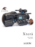
1
Xterà
User’s Guide
January 2007
AATON Xterà User Guide
AATON
2 rue de la Paix
BP 3002
38000 Grenoble
FRANCE
+33 4 7642 9550
+33 4 7651 3491 fax
E-mail: [email protected]
Web: http://www.aaton.com
Limitation of Liability
The information contained in this manual is distributed without warranty of any kind, express or implied. To the maximum extent permitted by law, Aaton and its licensors disclaim any and all warranties, express or implied, by statute or
otherwise, regarding this manual, including the fitness for a particular purpose, quality, or merchantability. Under no circumstances shall Aaton or its licensors be liable to the user of this manual or any other person for any incidental, special,
or consequential damages resulting from the use of this manual or the operation of the equipment described therein,
whether arising out of breach of warranty, breach of contract, or otherwise. Under no circumstances shall Aaton or
its licensors be liable for any damages arising out of the operation of the equipment described in this manual, whether
operated in a manner which is consistent with or contrary to the instructions contained therein, for physical abuse or
misuse of the equipment. No oral or written information or advice given by Aaton or its licensors, their respective employees, distributors, dealers, or agents, shall create any warranty. Aaton and its licensors further disclaim any and all warranties, express or implied, by statute or otherwise, regarding this manual, including the fitness for a particular purpose,
quality, or merchantability, regarding the equipment described in this manual, and in no event shall Aaton or its licensors
be liable for any damages, including but not limited to incidental, special, or consequential damages, arising out of the
use of the equipment, or any exposure of motion picture film used in the equipment.
2
TABLE OF CONTENTS
1
SYSTEM FEATURES AND CONTROLS
Front View
Rear View
Battery Side
Motor Side
LCD Control Panel - Quick Reference
2
1 0
1 1
1 2
1 3
14
THE CAMERA BODY
2.1 Lenses
ArriPL Lens Port
Installing the Lens
Aaton Lens Port
2.2 Viewing System
Viewfinder Options
Attaching the Extension Finder
Viewfinder Tension Adjustments
Adjusting the Diopter
The Eyepiece Shutter
Adjusting the Viewing Horizon
Viewing Screen
Changing the Viewing Screen
Adujsting the Viewing Screen
Aatonite Illumination
2.3 Mirror Shutter
Concept
Adjusting the Shutter
2.4 Film Gate and Pulldown Claw
2.5 Flange Focal Distance Adjustment
Concept
Polishing a Spacer
Changing the Spacer
Adjusting the Viewing Screen
Flange Focal Distances
2.6 Magazine
Installing the Magazine
Removing the Magazine
2.7 Power
1 8
1 8
1 8
1 9
1 9
1 9
20
20
2 1
2 1
22
2 2
23
24
2 4
2 5
2 5
2 5
27
28
2 8
2 8
2 8
29
2 9
2 9
2 9
3 0
3 1
3
Installing the Battery on the Camera
Battery Charging
Other Power Options
2.8 Motor
Camera Speeds
Using External Speed Devices
Electronic Inching
2.9 Lightmeter
Display
Operation
Using the Lightmeter without Running Film
Testing and Adjusting the Meter
Turning the Lightmeter Off
2.10 LCD Control Panel and Jog
The Aaton Jog
Understanding the Control Panel
Aatonite
AatonCode
ASA Setting
Battery Voltage
Camera Preset Speed
Camera Specific Speed
Speed Phasing
Feet or Meters
Footage Remaining
Footage Elapsed
Mag ID
New Magazine’s Footage
Camera Software Version Number
2.11 LED Indicators
Position and Meaning of the Diodes
Camera Test Indicator
Camera Run Indicator
Low Battery Indicator
End-of-Film Warning Sequence
8-hours Warning Sequence
2.12 VHR Assists
Installing the Control Unit
The Internal Beamsplitter
Positioning the Beamsplitter
The Beamsplitter Axis Adjustment
4
31
3 1
32
3 2
3 2
33
33
3 4
3 4
3 4
35
35
36
36
3 6
36
3 7
3 7
3 8
3 8
38
38
3 9
3 9
39
3 9
4 0
40
40
40
41
41
41
41
41
42
4 2
43
43
43
44
TABLE OF CONTENTS
The Manual Iris
Battery Life with VHR Assists
Installing the VHR Heads
The VHR Color VHR Assist
Menu Operation
3
THE MAGAZINE
3.1 Concept
3.2 Compatibility
DX Magazines
Super16 Safe
3.3 Pressure Plate System
The Picture Plate
The Claw Plate
3.4 Mag Identification System
Mag ID
Changing the ID of a Magazine
3.5 Loading
Feed Side - In the Changing Bag
Take-up Side - In Daylight
3.6 The GX 800 ft mag
Feed side, loading
Take-up side, loading
Mag ID
Footage
4
4 4
44
45
45
4 5
4 8
4 8
4 8
4 8
49
4 9
5 0
50
5 0
50
5 1
51
52
54
54
55
55
THE AATON SYSTEM
4.1 Camera Configurations
15mm Front Rods
Sliding Bridgeplate
4.2 Handgrip
Mounting the Handgrip
Handgrip On/Off Functions
Handgrip Adjustments
4.3 Tripod Use
4.4 Shoulder Operation
4.5 Carrying Handle
58
58
58
5 8
59
59
59
6 0
60
60
5
3/8 Accessory Screw
Mounting from the Carrying Handle
Tape Measure Stud
4.6 Transport
4.7 Extreme Conditions
Cold Weather
Warm Weather
5
CLEANING
5.1 Lens
Lens Elements
Lens Exterior
Mounting Surface
5.2 Body
Exterior
Mounting Surfaces
Camera Gate
5.3 Viewing System
Viewing Screen
Eyepiece
Viewfinder
5.4 Magazine
Exterior
Pressure Plates
Interior / Film Path
6
6
6
6
6
6
6
6
6
6
6
6
6
6
6
6
6
6
6
6
6
7
7
7
7
7
8
8
9
9
9
9
9
AATONCODE
6.1 Concept
6.2 The Internal Clock
6.3 OriginCplus
6.4 Initializing AatonCode in the Camera
Using the OriginCplus - Recommended Method
Using an External SMPTE Device
6.5 Monitoring and Maintaining AatonCode
Monitoring AatonCode with OriginCplus
Maintaining AatonCode without OriginCplus
6.6 The camera assistant duties
6
60
61
61
6 1
62
6 2
6 3
7 2
72
7 3
73
74
75
75
76
76
76
TABLE OF CONTENTS
Checking the Diodes
Setting the ASA
Checking for Running Time
7
77
7 7
77
TECHNICAL SPECIFICATIONS
List of Specifications
Connector - Pin Attributions
Available Viewing Screens
80
81
82
7
8
1
SYSTEM FEATURES AND CONTROLS
9
2
3
1
9
4
8
5
10
6
7
1.1 FRONT VIEW
1
2
3
4
5
6
7
8
9
10
10
Friction Adjusting Ring
Tape Measure Stud
Lateral Lock Knob
Beamsplitter Access Cap
VHR Cover
PL Lens Port
Wooden Handgrip
Eyepiece Lock Ring
Eyepiece Shutter
Body Run/Test Switch
adjusts the tension of the eyepiece swivel.
holds tape measure at film plane.
locks the lateral position of the viewfinder.
covers the port which accesses the beamsplitter adjustment screw.
accesses the VHR head.
standard mounting system for Xterà.Xterà.
allows for comfortable handheld operation.
fastens interchangeable standard and extension finders.
blocks light when operator's eye is away from the finder.
provides camera run and half frame inching.
GENERAL OVERVIEW
13
14
15
11
16
12
17
18
19
20
1.2 BACK VIEW
11
12
13
14
15
16
17
18
19
20
Magnetic Drive
Mag Release Lever
Amph9
Manual Iris Lever
Lemo14
Battery Lock Screw
Camera Fuse
XLR4
Lemo8
Lemo6
provides magnetic magazine coupling.
releases the magazine for removal.
accessory input provides +/-, Hz, and camera run functions.
controls CCD iris operation.
connects CCD head to the CCD control unit.
fastens the on-board battery to the camera body.
protects the body from excessive current and reverse polarity.
main power input for on-board battery
accessory input provides +/-, Hz, TVsync, and camera run
accessory input provides +/- and camera run functions.
11
22
27
26
21
23
28
24
29
25
30
1.3 BATTERY SIDE
21
22
23
24
25
26
27
28
29
30
12
VHR Control Unit
VHR On/Off
Carrying handle
Viewfinder Locking Ring
Run/Test Switch
Take-up Latch
On-board Batteries
LED Indicators
Lemo2
Adjusting Screw
fastens to the body for video operation.
powers the VHR assist (see VHR user's guide).
includes 3/8-16 accessory hole and adjusting tools.
locks left/right orientation
provides camera run and full frame inching from the handgrip.
locks the magazine take-up door.
2 x 12V NiMh for handheld operation.
LED side indicators for camera run, camera test and low battery.
input provides camera run functions.
adjusts the rotation of the handgrip.
GENERAL OVERVIEW
41
31
32
33
34
35
36
37 38
39
40
1.4 MOTOR SIDE
31
32
33
34
35
LCD Control Panel
Diopter Set Ring
Lemo5
Lightmeter On/Off
On/Off Rotating Switch
36
37
38
39
40
41
Motor
Aaton Jog
AatonCode Led
Feed Latch
Mag Footage Counter
Eyepiece Friction Ring
displays AatonCode, ASA, speed, voltage, remaining footage.
adjusts the diopter setting to the operator's eye.
AatonCode and SMPTE timecode communication.
activates the lightmeter display in the viewfinder.
for Run/Stop/Test fonctions. Includes LED Indicators motor side
indicators for camera run, camera test and low battery.
triphase salarium, low power consumption. 3-75 fps operation.
provides quick adjustment of Aatonite, ASA, speed, phasing, footage.
flashes each second if the timecode has been initialized in the camera.
locks the magazine feed door.
displays the footage remaining in the magazine feed side.
allows friction adjustments for short / Long eyepiece.
13
1.5 LCD CONTROL PANEL - QUICK REFERENCE
IN SHOW MODE
24’ - 080
ISO = 100
Batt = 10’4
Ela = 042
22=32=54
95-03-25
123456
2321
Camera speed and Remaining footage
Film ASA
Battery voltage
Elapsed footage during last take
Hours=minutes=seconds in AatonCode
Year-Month-Day in AatonCode
Production ID in AatonCode
Equipment number in AatonCode
(default mode)
(1 x Batt/Iso)
(2 x Batt/Iso)
(2 x Speed)
(1 x Time)
(2 x Time)
(3 x Time)
(4 x Time)
IN SET MODE
Sp =2 4’
Sp = 27’454
Et
Phase
ISO = 100
MAG = 400
MAG = 140
Adjusting a preset speed
(SET, 1 x SYNC, toggle SYNC or use Jog)
Adjusting a specific speed
(SET, 1 x VAR, use Jog)
Speed controled by external speed device
(SET, 2 x VAR)
Phase Adjusting
(Camera running,SET, 2 x VAR, use Jog)
ASA Setting
(SET, 1 x ISO, toggle ISO or use Jog)
Indicating that the new magazine is fully loaded
(SET, 2 x MAG)
Indicating the new magazine's footage
(SET, 1 x MAG, use Jog)
WARNINGS
Lo Spd
Lo Batt
Empty
Unadjust
No Code
14
Camera has not yet reached the selected speed
Battery is too low (below 10V)
No more film in the magazine
Please check page 39
Blinking "No Code" means no timecode in the camera (press one button to
remove this message).
GENERAL OVERVIEW
15
2
THE CAMERA BODY
17
2.1 LENSES
The Xterà's flexible lens mounting system allows for the use of a
wide variety of 16mm, 35mm and still-photographic lenses.
Flange focal distance
Refers to the critical distance
from the lens seat to the film
plane. The precise FFD of the
Xterà is 52mm -8 to -17µm as
measured with a depth gauge
in the lens port. It is recommended that these tolerances
be checked and maintained
by a qualified technician. The
combination of FFD and back
focus distance of a lens directly
affects precise focus and overall
image sharpness. Make sure
these critical measurements are
strictly upheld. When using
an unfamiliar lens for the first
time, check that the eye focus
matches the tape-measured
focus marks of the lens, and /
or shoot a focus test.
2.1.1 ArriPL Lens Port
The ArriPL lens port is the standard mounting system delivered
with the Xterà and allows the use of all 16 and 35mm ArriPL
mounted motion picture lenses. PL lens adaptors are available for
Arri standard and Arri bayonet mounted lenses. This mount is ideal
for rental facilities, where a mounting system compatible with other
manufacturer’s 16 and 35mm cameras is often desired. The specific
flange focal distance (FFD) of the Xterà with PL port is 52mm -8
to -17µm.
2.1.2 Installing the Lens
To install the lens on the camera body, turn the outer locking ring
counter-clockwise until it reaches its stop. If the port cap is on,
remove it. Align the four protruding flanges on the lens with the
four corresponding cutaways in the locking ring and insert the lens
into the camera port so that its flanges rest evenly against the lens
seat. Tighten the locking ring by turning clockwise until the lens is
18
THE CAMERA BODY
secured in place and the lock ring is firmly set. Make sure the lock
ring is tight enough so that it cannot be inadvertantly unlocked.
2.1.3 Aaton Lens Port
The Xterà can also be equipped with an Aaton lens port. In order
to install the Aaton port, the ArriPL lens seat and locking ring must
first be removed.
Because the FFD of the Aaton lens port is shorter than most professional cameras (40mm), the Xterà, equipped with this mount, can
accommodate most motion picture and still camera lens mounts.
Lenses can be used equipped with an Aaton mount or by adapting
another manufacturer’s lens mount. Aaton lens adaptors are available for Arri standard, Arri bayonet, as well as Nikon and Leica-R
photographic mounts.
2.2 VIEWING SYSTEM
2.1 Viewfinder Options
The viewfinder is designed to be fully orientable, providing left or
right side viewing and an upright image in any position.
The viewfinder is equipped with a standard short eyepiece that can
be used for handheld and tripod-mounted operation. For more
comfortable tripod and studio applications, the standard extension
The Pechan prism
In order to provide a fully
orientable upright image, the
Aaton viewfinder incorporates
a pechan prism assembly,
which is actually comprised
of two triangular prisms sandwiched together. On some
viewfinders, depending on the
construction of this prism,
rotation of the eyepiece a full
360° will cause the image in
the finder to shift slightly left
or right.
After attaching an extension
finder, if the image in the
finder appears to have shifted
slightly, rotate the finder 360°
and choose the preferred centered image.
19
finder can be fitted in place of the short eyepiece. With an Elemak
or Mitchell type dolly, or in situations requiring additional reach, the
hyperlong finder can be used.
Note that standard short eyepiece can be equipped with a heating
system, as well as 250mm eyepiece extension in order to avoid any
condensation on the eyepiece lens. Aaton can provide you a heating
lens (neutral, + 3 or - 3 diopters) and the corresponding cable.
2.2.2 Attaching the Extension Finder
In order to use an extension finder on the Xterà, the standard eyepiece must first be removed. To remove the eyepiece, locate the
eyepiece lock ring, marked A in the photo below. Rotate counterclockwise and gently pull off the eyepiece. To install the extension
finder, locate the protruding guide pin on the seat of the viewfinder
and align the pin with the hole in the flange of the finder. Mate the
flange to the seat of the viewfinder and tighten the lock ring until it
is set firmly in place. During this procedure, you will notice that the
extension finder needs to face 180° away from the operator’s eye to
be installed onto the viewfinder. Because of its optical construction,
this is completely normal. After installation, rotate the finder 180°
to regular viewing position.
2.2.3 Viewfinder Tension Adjustments
The large knurled knob at the base of the left/right lateral movement point (b) locks the lateral positioning.
The friction adjusting ring, located behind the eyepiece lock ring,
can be used to adjust the tension of the eyepiece swivel, depending
on the operator’s preference and the viewfinder being used. When
using the standard eyepiece, tension should be relatively light to
allow for movement with a moderate amount of pressure. When
using the standard extension finder, tension should be increased to
hold the additional weight of this finder in place.
To adjust the tension of the swivel, loosen the friction adjusting ring
20
THE CAMERA BODY
d
c
b
a
(c). Hold the eyepiece in place, rotate the adjusting ring slightly.
To increase tension of the eyepiece swivel, rotate the adjusting ring
clockwise; to decrease the tension, rotate the adjusting ring counterclockwise.
2.2.4 Adjusting the Diopter
Before shooting, the diopter setting of the viewfinder should be adjusted to the operator’s eye. To set the diopter (d) look through the
viewfinder, rotate the diopter set ring until the edge of the crosshair is at its sharpest point. It is recommended that, for easiest setting, this adjustment be performed with the port cover off and no
lens on the camera.
Notice that the diopter set ring is engraved with numbers and dots use this reference to quickly recall your particular setting when more
than one person will be looking through the view-finder.
The range of the diopter setting is + or - 3. If the range does not
reach your particular diopter setting, the viewfinder optics can
quickly be adjusted by a qualified technician and the diopter range
reset to meet your needs.
2.2.5 The Eyepiece Shutter
In order to avoid unwanted light seepage through the viewfinder,
the eyepiece shutter must be closed any time the camera is running
film and the operator’s eye is away from the viewfinder.
21
To close the eyepiece shutter on the standard bellows eyepiece and
250mm extension, grasp the ring at the base of the eyecup and rotate 1/8 of a turn counterclockwise.On the hyperlong finder, rotate
the knurled ring closest to the eyecup counter-clockwise to close the
shutter.
Checking your Viewing
Horizon
here is a simple means of
determining whether adjustment of the horizon needs to
be made. Mount a zoom lens
onto the camera and rest the
camera on your shoulder in a
standard handheld position.
Look through the viewfinder
with your right eye while also
keeping your left eye open.
Compose a frame that includes
vertical or horizontal lines (a
window frame, for example)
and adjust the zoom of the lens
so that the focal length of the
lens generally matches what
you see with your left eye.
Ignore the viewing screen
markings for the time being
and determine whether the
rotation of the image you see
through the viewfinder matches what you see with your left
eye. If it does not, then a fine
adjustment may be necessary
22
2.2.6 Adjusting the Viewing Horizon
If the rotation of the image seen through the cameras viewfinder
does not exactly match what is seen through the naked eye, there is
a fine adjustment that can be made to the image’s relative horizon.
Locate the small slotted screw located on the underside of the
viewfinder just inside the eyepiece lock ring. Notice that the screw
travels in an elongated cutout. Loosen the screw one turn and, while
looking through the viewfinder, move the screw within its cutout
in order to adjust the horizontal rotation. When the images seen
through your left and right eyes coincide, lock the screw.
2.2.7 Viewing Screen
The unique concave design of the Aaton fiber optic viewing screen
gives it its superior sharpness and lucid quality. If your viewing
screen possesses a dark blemish or two, don’t be alarmed; these
spots are actually fractured fibers and are inherent in the manufacturing of fiber screens. Such blemishes, although occasional, are the
trade-off for the brilliant screens which result from the use of this
technology.
The Xterà utilizes an interchangeable viewing screen system which
allows the cinematographer to install the screen which best suits
his particular application(s). Aaton offers ten viewing screens as
standard. (see the Technical Specifications chapter) Specially marked
screens can also be manufactured to order. Contact you local Aaton
representative for details.
Unlike the XTRplus, which uses a universal screen that shifts between std 16 and Super16 operation, the Xterà requires separate
screens for std 16 and Super16 formats.
THE CAMERA BODY
2.2.8 Changing the Viewing Screen
The viewing screen is designed to be easily removed by the user
for the purposes of interchanging or for cleaning. To remove the
screen, unscrew the black tool marked Vw located in the hollow at
the rear of the camera’s carrying handle. Remove the port cap. Clear
the mirror shutter so that it is rotated safely inside the body by rotating at the base of the shutter with your finger or by setting the
camera to test position, then removing the battery. Look into the
port and locate the threaded hole directly above the aperture opening and screw in the tool until it is snug. Carefully pull the screen
straight out.
To reinstall the screen, screw the Vw tool into the threaded hole
of the screen until it is snug. Look into the port and locate the left
and right lip of the viewing screen holder. With its flat side facing
down, gently push the screen straight into the holder above the lip
until it seats firmly in place. Unscrew the Vw tool and store back in
the hollow of the carrying handle. Reaffirm that the screen is seated
properly by carefully pressing against the threaded hole with your
thumb.
23
Warning !
Each time you're touching the
mirror, the viewing screen, or
anything inside the lens port,
disconnect the battery. You
will therefore avoid any risk
of seriously damaging your
camera.
2.2.9 Adjusting the Viewing Screen
The image on the viewing screen should be sharp, and its focus
should match to that of the film. This can be best determined with
the use of a collimator, or by looking through the viewfinder and
checking that the sharp focus of a lens matches the measured distance on its barrel. If it does not, then you need to make an adjustment of the viewing screen focus.
To proceed, you must first unscrew and remove the circular cap located on behind the camera body Run/Test switch.Inside the access
hole, inser a 2mm Allen wrench and screw or unscrew it. Replace
the circular cap. Use a collimator to check that you have reached the
sharpest focus of the viewing screen image. If the image is not yet
sharp ennough, proceed again.
2.2.10 Aatonite Illumination
The Xterà features illuminated viewing screen markings referred
to as Aatonite. The level of illumination is adjustable by the user
via the Jog wheel, which is located to the right of the motor. To
24
THE CAMERA BODY
operate Aatonite, power the body and switch the run/test switch to
test position and off again to turn on the camera electronics. Look
through the viewfinder and rotate the jog to set the desired level
of illumination. The markings will remain illuminated for a full 2
minutes after the camera is set in the off position. The illumination
level set in test position will be memorized and recalled once the
camera is run. The illumination level can also be readjusted while
the camera is running.
The configuration of illuminated markings will differ slightly between screen types. Refer to the screen illustration on page 21 for a
specific description of each screen type along with its corresponding Aatonite markings.
2.3 MIRROR SHUTTER
2.3.1 Concept
The reflex mirror shutter is designed to provide an optical path to
the viewfinder while the claw movement advances the film to the
next frame.
The shutter features a four-position user-adjustable opening:
• Standard 180° for filming
under standard 60 Hz HMI lighting at 24 fps _or_
under standard 50 Hz HMI lighting at 25 fps without
flicker • 172.8° for filming
at 24 fps under 50 Hz HMI lighting without flicker.
• 150° for filming
at 25 fps under 60 Hz HMI lighting without flicker.
• 144° for filming
to minimize the roll bar while filming an NTSC broadcast
monitor at 24 fps.
2.3.2 Adjusting the Shutter
To adjust the shutter opening, unscrew the blue shutter tool marked
Sh located in the hollow at the rear of the camera’s carrying handle.
25
Make certain that the battery is off the camera and remove the port
cap. Locate the tool guiding hole to the lower right of the inside of
the lens holder (see diagram). Gently rotate the shutter at its base
with your finger until the brass driving gear is centered underneath
the tool guiding hole. Insert the shutter tool through the guiding
hole and into the brass gear. Rotate the tool until the appropriate
notched shutter setting is reached; turning counterclockwise will reduce the shutter opening, turning clockwise will increase the opening.
Sh
When setting the opening to 172.8° or 144°, a shutter blade indicating these settings will be visible from behind the left edge of
the mirror. Make sure the white line to the immediate right of the
172.8° and 144° markings meet the left edge of mirror. When the
adjustment is complete, remove the tool and store back in the hollow of the carrying handle.
26
THE CAMERA BODY
2.4 FILM GATE AND PULLDOWN CLAW
2.4.1 Co-planar Movement
All Aaton cameras incorporate a patented means of advancing the
film called a co-planar claw movement. By utilizing this technique,
Aaton is able to achieve an ultra-precise pulldown with a minimal
number of moving parts. The co-planar concept is the key to the
camera’s low-noise operation.
The film gate also features a side pressure bar which is recessed into
the claw-side rail at the point of image exposure to assure maximum
lateral stability.
This unique, straight forward mechanism design results in horizontal
and lateral film registration that is superior to all other 16mm camera movements with an accuracy of 1/2000 of the image dimensions.
4.2 The Hair-Free Gate
In most 16mm camera designs, there is a certain amount of film
dust (also referred to as fluff or hair) that is generated as film rolls
through the magazine and enters the camera gate. Because the gate
and pulldown are the areas where the film must be held most rigidly,
these are also the areas where most of the accumulating film dust
tends to be deposited. The result could be a visible hair in the picture area and an unuseable shot.
Aaton has taken steps in the design of their magazines and gate assembly to ensure hair and dust-free images. The Aaton magazine
features a twistless film path with little sprocket contact, which
minimizes the amount of film dust that builds up before entry into
the aperture area.
4.3 Cleaning the Gate
In order to avoid film dust buildup in the recessed channels of the
gate, the gate should be inspected during magazine changes and
27
cleaned every three to four mags if the shooting schedule permits.
Refer to the Cleaning chapter for more detailed information.
2.5 FLANGE FOCAL DISTANCE ADJUSTMENT
2.5.1 Concept
For a few years now, Aaton has inserted a spacer between the lens
port and the camera body. This thin (0.3mm) metallic ring is responsible for the precise distance between the lens port seat and the
film plane called the flange focal distance (FFD), and therefore it is
also mainly responsible for the sharpness of the images.
Anyone who would like to change the FFD of his own camera
should now do so by simply changing the spacer, and only with the
spacer. He has not to polish any other surface, ot to insert anything
else between the lens port and the film plane. For that purpose, you
can order some aluminium spacers (0.35mm) to Aaton, and then
safely change the FFD of your camera.
2.5.2 Polishing a Spacer
In order to fine-adjust the thickness of a specific spacer, Aaton
carries a specific tool (ref 09 202 92) designed to hold the spacer
firmly and evenly against Emery paper. When polishing a spacer,
always work on a perfectly flat worktable or stone, and be sure to
hold the tool firmly.
2.5.3 Changing the Spacer
The spacer is placed between the lens port and the camera body’s
titanium lens holder. If you’re camera is equipped with a PL lens
port, you first need to remove the lens locking ring: screw two or
three turns its stop (placed on the bottom, inside the PL port), and
turn the ring counterclockwise.
Remove the lens port by unscrewing its screws. Then remove the
aluminium spacer gently.
Once you have placed a new spacer, replace the lens port, then the
28
THE CAMERA BODY
lenses locking ring. Do not forget to unscrew two or three turns the
locking ring stop, if you have a PL lens port.
2.5.4 Adjusting the Viewing Screen
Because you have changed the distance separating the base of the
lens and the camera body, the image on your viewing screen might
now appear to be less sharp than usual. Most likely, you may need to
readjust the precise focus of the viewing screen. Refer to the 2.2.9
section of this chapter to proceed.
2.5.5 Flange Focal Distances
Here are the flange focal distances for all the lens port available for
the Xterà.
Mont
Aaton (AA)
Arriflex (PL)
Panavision (PV)
Reference
01 112 35
01 113 20
01 113 25
FFD
40.00 mm
52.00 mm
57.15 mm
Diametre
50.00 mm
54.00 mm
49.50 mm
Adjustment
-8 / -17 microns
-8 / -17 microns
-8 / -17 microns
2.6 THE MAGAZINE
The Aaton magazine holds 400 ft (122m) of standard 16mm or
Super16 film. Shooting at 24 fps, a 400 ft roll will run for 10.5
minutes; shooting 30 fps, the same roll will run for approximately
9 minutes. The coaxial design of the magazine allows for complete
self-contained threading, quick mag changes and a minimal amount
of loading to be performed in the changing bag. Loading the magazine is a simple operation that, with practice can be performed in a
little over a minute. Refer to the Magazine chapter of this manual
for complete details on loading and caring for magazines.
2.6.1 Installing the Magazine
The instant mag design allows for instantaneous switching between
mags on the set. To install the magazine on the camera, situate
29
yourself towards the rear motor side of the camera body. If the
aperture cover plate is on, remove it. Place your left hand around
the front of the camera just underneath the lens area. Grasp the
magazine firmly with your right hand below the midway point of its
rear. While holding the camera body with your left hand, guide the
magazine along the base of the camera into the aperture area. Make
sure that the top edge of the throat of the magazine is parallel to
the carrying handle of the camera as you guide the mag in place.
Push firmly and evenly until you feel and hear the magazine snap
into place.
2.6.2 Removing the Magazine
To remove the magazine, situate yourself as before, towards the
rear motor side of the camera. Grasp the magazine anywhere which
is comfortable at its rear. Place your hand above the motor of the
camera and push the mag release lever towards the front of the
camera with your thumb. Pull the magazine straight off the camera
with your right hand.
30
THE CAMERA BODY
2.7 POWER
Xterà body requires only 12 volts for all aspects of operation. One
standard Aaton on-board (12V 3,5 Ah rechargeable Nimh) will
power the camera, video and any accessories which are connected to
the body’s accessory inputs (such as zoom controls, speed controls
etc.) through a standard 4 pin XLR connector. Two 3,5 Ah onboard batteries can be installed on the Xterà.
2.7.1 Installing the Battery on the Camera
In order to install, loosen the blue knurled screw approximately four
or five turns. Push the battery evenly onto the XLR4 connection on
the body. When snug, tighten the knurled screw onto the battery tab
to hold it in place.
When running AatonCode, get into the practice of having a fresh
battery on hand before removing one from the camera. Even a low
battery that no longer runs the body (below 10V) will have enough
voltage to keep accurate time counting.
Thanks to a super capacitor built into the camera base, you will have
a full minute to change the battery before time is lost. After replacing the battery, confirm that time is still counting by looking for
the yellow blinking diode to the right of the motor or checking the
control panel.
2.7.2 Battery Charging
The Aaton on-board can be recharged with an appropriate 12V
Nimh battery charger.
For the best results, use a microprocessor-controlled charger or a
standard trickle charger with a charging output of at least 200ma,
both of which prevent the overheating and mistreatment of your
Nimh cells. Always follow the specific guidelines of the charger
manufacturer. You can use the Aaton ChA-3, designed to charge
31
Nimh Batteries Tips
Follow a few simple rules to
insure the long life of your
Nimh cells:
• Allow batteries to run
through their normal cycle
of charging and use. Avoid
topping off partially full batteries. Once every few months,
discharge cells to 8-10V using
a standard discharger to minimize their memory.
• Do not rapid-charge your
cells more than necessary, as
the added heat will eventually shorten their life span.
Instead, recharge batteries at
a normal charging rate when
your schedule allows.
• If your batteries will not be
used for long periods of time,
always store them in a cool, dry
environment fully charged.
two standard batteries in 5 hours, without any risk.
Beware of older, timed chargers manufactured when 1.2 and 1.4ah
batteries were the norm; these chargers were most likely rated for
the lower amperage batteries of that time and will consistently undercharge the higher rated Nimh cells of today.
2.7.3 Other Power Options
Since the Xterà power input is a standard 4pin XLR type, a great
variety of 12-14 volt sources can be used to power the camera. This
includes AC power supplies, battery blocks, lithium cells and car
batteries.
Get into the habit of carrying a standard XLR4 powercable in your
package in case an alternative power source is needed. Regarding
AC power supplies, it is recommended that the unit you use be at
least 4 amps and 25 watts. Before connecting any non-standard
source, always make sure that the pin configuration of the unit is
correct. See the Technical Specifications chapter of this manual for
details for proper wiring.
2.8 MOTOR
The tri-phase samarium motor design of the Xterà provides low
power consumption and improved stability at high speeds. The body
is capable of speeds between 3 and 75 fps with a standard 12V battery.
2.8.1 Camera Speeds
The Xterà provides boths preset crystal speeds (in sync mode) and
specific crystal speeds (in variable mode) in .001 increments, all accessible from the LCD control panel. Available preset speeds consist
of 6, 12, 18, 20, 23.98, 24, 25, 29.97, 30, 36, 40, 48, 60 and 75 fps.
The preset speed selector (SYNC) allows for quick access to these
frequently used speeds. If any other speed is desired, or if the camera speed must match the frequency of a monitor to eliminate a roll
bar, the specific speed selector (EX/VAR) should be employed. The
32
THE CAMERA BODY
specific speed selector enables the body to run at any speed between
3 and 75 in .001 frame increments. A phase adjustment of the variable speed is accessible from the EX/VAR selector.
The camera speed can also be adjusted while the camera is running
in either sync or variable mode. For more information on these
speed functions, refer to section LCD Control Panel and Jog of this
chapter.
2.8.2 Using External Speed Devices
The Xterà can be driven externally from devices such as film/video
synchronizers, speed aperture computers and external speed controls. In these situations, the camera EX/VAR selector must be set
to Et. If such a device is connected and the selector is not set to Et,
the camera will run at the speed indicated on the display.
Keep in mind that, with certain manufacturer’s speed controls, it
may be possible to run the camera at speeds higher than the 75
fps factory limitation. Overcranking in such a way, however, will
increase mechanism wear, increase noise and compromise image
registration. Aaton urges to avoid such usage at all cost and will not
be responsible for the resulting damage that may occur. This top
speed cap of 75 fps has been designated by Aaton because it is the
level at which the camera can run safely without any adverse effects
on its mechanics.
2.8.3 Electronic Inching
The inching function of the motor is accomplished electronically
and can be accessed in a number of ways.
•From the Body
The large run/test switch on the motor side of the body, not only
runs the camera, but provides half frame inching for gate inspection, lightmeter functions and loop situating when installing a fresh
mag.
•From the Handgrip
The wooden handgrip switch, by way of the Lemo2 connector, provides camera run and full frame inching for single frame operation
33
and loop situating.
•From a Remote Cable
The Lemo2 connector, as well as Lemo6, Lemo8 and Amph9 accessory connectors, provide the capability of using a remote on/off
with either a half-frame or full-frame inching function.
2.9 LIGHTMETER
The Xterà is equipped with an internal lightmeter that is designed
to read the quantity of light reflected off the film itself. For added
accuracy, the meter measures the light by means of two photocells.
The metering system automatically compensates for filters and
changes in camera speed.
2.9.1 Display
Through the viewfinder, the lightmeter display is positioned directly below the viewing screen across the bottom of the frame.
A single darkened diode moves across an array of 13 yellow and
green diodes, indicating proper exposure (see diagrams). Each diode
represents one third of a stop, while normal exposure darkens the
center green diode. Underexposure of -2 stops or more darkens the
green diode on the left end of the row; overexposure of +2 stops
or more darkens the green diode on the furthest right of the display.
To the immediate left of the display is the red diode indicator,
which has the same functions as the red diodes on the left and right
sides of the body. See section LED Indicators for further details.
2.9.2 Operation
Because the lightmeter takes its measurement as a reflection off the
film, you must have film in the gate for the camera to provide an accurate reading.
To use the lightmeter, follow these simple guidelines: Set the ISO
selection on the control panel to the exposure index of the film
stock being used. Set the camera to run or test position and adjust
the lens iris until the center green diode is darkened; this will be
34
THE CAMERA BODY
your proper metered exposure.
Remember, the lightmeter is giving you an average reading of the
entire frame. You may choose to vary the suggested exposure according to subject conditions.
2.9.3 Using the Lightmeter without Running Film
It is also possible to use the lightmeter without actually running the
camera. Set the ISO selection to the exposure index of the film being used. Set the camera to test position using the on/off switch on
the body or the handgrip. If the handgrip is used, the momentary
switch must be held in the test position. The mirror shutter will rotate 180° allowing light from the lens to reach the film and a reading
to be taken by the meter. Adjust the lens iris until the center green
diode is darkened, indicating proper exposure.
2.9.4 Testing and Adjusting the Meter
If you are operating the lightmeter for test purposes, don’t forget to
have film in the gate before taking a reading
The following is the procedure for checking and adjusting the sensitivity reading of the lightmeter:
• 1 - Evenly light a standard 18% grey card.
• 2 - With a loaded magazine and lens on the camera, frame the
chart so that it completely fills the Super16 frame.
• 3 - With a properly calibrated handheld lightmeter, take a reading
of the grey surface and set the T stop of the lens accordingly.
• 4 - Switch the camera to run or test position and check the position of the darkened diode. If the center green diode is darkened,
the camera’s lightmeter is set correctly. If the darkened diode is to
the left or right, it is possible to adjust its reading.
Single Frame Operation
You may use the wooden
handgrip Run/Test switch of
your camera to shoot a single
frame: just press this button to
Test and immediatly release it.
In that case, the film is exposed
during 1/4 second.
But you need to know that
the Xterà chamber is still not
opaque enough so that more
than 10 minutes can separate
two single image shots. To
use an Aaton camera in single
image shooting, you'd better
use an intervalometer and a
lens capping shutter.
35
• 5 - To access the lightmeter potentiometer, remove the complete
viewfinder by means of the four screws which mount it to the front
housing. Locate the hole between the two viewfinder screwholes on
the top motor side of the front housing. The white potentiometer
will be visible within this hole.
• 6 - With a small screwdriver, adjust the potentiometer slightly;
1/8 of a turn will have an effect. Rotating clockwise will correct
an overexposure and move the darkened diode to the left; rotating
counterclockwise will correct an underexposure.
• 7 - In order to check your adjustment, replace the viewfinder,
tighten the four screws and repeat the procedure from step 4. When
the reading through the camera matches your handheld meter, the
adjustment is complete.
2.9.5 Turning the Lightmeter Off
If the lightmeter is not being used, it may be turned off. The on/
off toggle switch is located on the operators side to the left of the
motor. Keep in mind, the red diode indicator and end-of-film warnings will function whether the display is on or off.
2.10 LCD CONTROL PANEL AND JOG
2.10.1 The Aaton Jog
Located to the immediate right of the motor, the Aaton jog is a
small wheel designed to simplify many user functions. When used in
conjunction with the control panel, the jog allows quick adjustment
of some of the otherwise time-consuming parameters (such as the
setting of a precise 5-digit speed or a film short end)
2.10.2 Understanding the Control Panel
The LCD control panel consists of an illuminated display and five
buttons to access information (see diagram). The control panel operates in two modes: Show and SET. To show a parameter without
adjusting, go directly to one of the four function buttons (1 through
36
THE CAMERA BODY
4 in the diagram) to view relative information. To set a parameter,
first press SET, then go to the appropriate button. Information is
changed by either toggling that button or by rotating the jog, depending on the parameter. Pressing SET afterwards (or waiting for 7
seconds) will enter your selection.
Capped text ( SYNC, EX/VAR, ISO, MAG) refers to those functions adjustable while in the SET mode; standard text (Fps/Ft, time,
batt/iso, elapse) refers to those functions accessible directly in the
default Show mode.
Note that, while viewing a Show function on the control panel, any
inactivity longer than 10 seconds will revert the display back to its
default mode (speed and remaining footage). As mentioned previously, any break longer than 7 seconds while in SET mode will automatically enter the last selection.
The following parameters can be accessed from the LCD control
panel in conjunction with the jog. For more concise information,
see the table in the System Features and Controls chapter of this
manual.
2.10.3 Aatonite
In its default mode, the Jog controls the level of Aatonite viewing
screen illumination from zero to full brightness.
Adustment Tips
While adjusting the sensitivity of the lightmeter, you may
wish to use your direct view of
the display through the body's
top cavity for reference. If
so, there are a few points to
remember:
• Because the image is inverted
without the viewfinder in
place, your adjustments will
move in the opposite direction
than what is seen through the
finder.
• Since the cavity is open, light
will enter through this opening, making any reading inaccurate by 1/3 to 2/3 of a stop.
Therefore, only use the direct
view of the display to reference
the number of diodes adjusted.
Always check your final adjustment with the viewfinder in
place.
2.10.4 AatonCode
As a standard feature, the Xterà is equipped with the capability of
recording AatonCode in-camera time. Timecode information is
exposed onto the film by means of seven micro-diodes, which are
relayed, by means of fiber optics, into the gate above the claw to the
right of the aperture opening. These micro-diodes flash rapidly to
form the code as the film rolls through the gate between exposures.
For more elaborate information regarding the uses and functioning
of AatonCode, OriginCplus and other related devices, refer to the
AatonCode chapter of this manual.
If AatonCode has been initialized in the camera, press button Time
to view timecode information. Toggling button Time will display
37
hour/minute/second, then year/month/day, then the six-digit production ID, then the camera’s equipment #, in that order.
2.10.5 ASA Setting
When using the internal lightmeter and/or AatonCode in the Xterà,
the ASA (ISO) setting must be adjusted to the exposure index of
the film stock being used. The ISO selector on the LCD control
panel provides settings between 25 and 1000 ASA.
With regards to the lightmeter, the setting on the ISO selector dictates to the camera what the exposure should be for a particular film
stock. For AatonCode, proper ASA / ISO selection will insure that
the timecode matrix recorded on the edge of the film in the gate
will be exposed at an appropriate and useable level.
Press button Batt/Iso twice to view the ASA selection. To adjust
the ASA setting, press SET, then button Batt/Iso. Make your selection between 25 and 1000 ISO by toggling Batt/Iso or by rotating
the jog wheel.
If the ISO selector is adjusted while the camera is in test or run position, the correction will not take place until the next camera start.
2.10.6 Battery Voltage
Press button 3 to read the voltage of the camera’s power source.
Notice that, if the camera is running and button 3 is pressed, the
control panel will read and display the voltage under load.
2.10.7 Camera Preset Speed
The default mode of the control panel will automatically display
the camera speed selection, whether it be in sync or variable mode,
when the camera is powered but not running. When the camera is
turned on, the actual running speed to the .01 frame is displayed.
To adjust the preset speed, press SET, then button SYNC. Make
your selection of stepped crystal speed between 6 and 75 fps by
toggling SYNC or via the jog wheel.
2.10.8 Camera Specific Speed
38
THE CAMERA BODY
To choose a specific speed press SET, then EX/VAR. Make your
selection of any .001 incremented crystal speed between 3.000 and
75.000 fps via the jog.
To set the camera to be driven from an external source (such as
film/video synchronizer or external speed control), press SET, then
EX/VAR twice. Et will be displayed, indicating that camera is set in
external mode.
2.10.9 Speed Phasing
The phasing of the variable speed can be set to eliminate a roll bar
while filming a monitor. Operate first with no magazine on the
camera, because you first need to synchronise the camera speed to
the monitor frequency. Run the camera. Press SET, then EX/VAR
once, turn the jog, until the roll bar seems stable on the screen.
Press SET to enter. Stop the camera, and then install a magazine.
Run the camera. Press SET, then EX/VAR twice. Look through the
camera at the monitor and press EX/VAR until the roll bar is out
of view. Press SET to enter.
Force Processing and
the
AatonCode matrix
Regardless of the situation,
always set the ASA selector to
the actual exposure index of
the film. If you know beforehand that your footage will be
pushed or pulled, don't worry
about compensating for the
sake of the precise exposure of
your timecode matrix. The
matrix is resistant enough to
handle exposure variances of
one and a half stops or more in
either direction.
2.10.10 Feet or Meters
The control panel can be set to count in either feet or meters in the
following manner. Unplug power from the camera until the display
goes dark. Simultaneously press button MAG while plugging power
back in. Continue to hold button MAG and set camera Run/Test
switch to test position; foot or meter will show on the display. Toggle button MAG to make your selection.
2.10.11 Footage Remaining
The control panel will display the memorized footage remaining any
time the camera is running with a magazine on.
2.10.12 Footage Elapsed
With the camera stopped, press button MAG to view the elapsed
footage of the previous camera run. With the camera running, press
39
MAG to view the elapsed footage of that particular take. The display will revert back to the default mode (speed and remaining footage) after 10 seconds.
Changing Speeds while
Running the Camera
Any camera speed, wether preset or specific, can be changed
when the camera is running.
To do so, run the camera, then
follow these simple steps:
• Operating under a preset
speed (in sync mode), press
SET, then SYNC, then use the
jog wheel to choose a higher
or lower stepped speed.
Under a specific speed (in variable speed), press SET, then
VAR, then use the jog to ramp
the speed higher or lower in
.001 frame increments.
2.10.13 Mag ID
The Xterà will recall the footage according to the mag ID, which
distinguishes seven magazines (A through G). To check the ID of a
particular mag, as read from the control panel, press button MAG
twice; the letter ID on the display should coincide with the letter on
the mag’s feed side door. For more information regarding Mag ID,
refer to the chapter entitled The Magazine.
2.10.14 New Magazine’s Footage
With a fully loaded magazine on board, press SET, then button
MAG twice to reset the control panel to count down a full 400 ft
load. If a short end is being used, press SET, then button MAG,
then reset the desired footage via the jog.
Note that the camera does not take a physical reading of the film
roll to determine the footage reading on its display; it is only a
counter and it must be set by the user. There is, however, a mechanical footage counter on the magazine that automatically measures
the size of the camera roll; use the magazine footage counter to determine the correct short end length to input on the control panel.
2.10.15 Camera Software Version Number
If you need to know the software version number your camera is
equipped with, proceed as follow. Unplug the battery fron the camera. Put the camera on Test mode. Then, while pluging back the
battery, watch carefully the LCD control panel. During one second
it will display the camera software version number.
2.11 LED INDICATORS
40
THE CAMERA BODY
The Xterà utilizes LED indicators in three locations to convey information: in the viewfinder and on both left and right outsides of
the camera body.
2.11.1 Position and Meaning of the Diodes
• Two yellow diodes, placed on both right and left sides of the camera body indicate that the camera is either on Test or on Run mode.
• Two red diodes, placed on both right and left side of the camera
body, and a third one, visible from the viewfinder, display a special
warning.
• One yellow diode, located to the right of the Jog wheel and called
the timecode diode, flashes each second if the timecode has been
initialized in the camrea.
Displaying a 5 Digit
Speed
If the Xterà is set to a variable
(5-digit) speed, the control
panel will only display that
speed to the .01 digit. Keep
in mind, the display will not
rounf off the speed, but simply leave off the last digit. For
example, if the 5 digit speed of
23.976 is entered, the control
panel will display 23.97, not
23.98.
2.11.2 Camera Test Indicator
� Yellow diode is on.
� � � � � Red diode is blinking fast.
2.11.3 Camera Run Indicator
� Yellow diode is on.
� Red diode is off.
2.11.4 Low Battery Indicator
� Yellow diode is on.
� � � � � � � Red diode is flashing slowly.
The LCD control panel displays Lo Batt.
2.11.5 Low Speed Indicator
� Yellow diode is on.
� � � � � Red diode is blinking fast.
The LCD control panel displays Lo Speed.
2.11.6 End-of-Film Warning Sequence
The lightmeter display features pre-end-of-film and end-of-film
Remember…
Variable Speed for Phasing
Keep in mind, the speed phase
function of the control panel
will only operate when a variable speed is initially selected.
When shooting 29.97, for
example, be sure to choose
the specific 29.970 instead of
the preset 29.97 if you plan to
incorporate the phase function
for that particular shot.
41
warnings for the operator.
Under normal operation, the lightmeter display will flash once for
every foot or meter that is counted down. When the footage counter on the LCD control panel counts down to 10 feet remaining, the
display will flash more rapidly, at a frequency of about 2-3 times per
second. Keep in mind, the pre-end-of-film warning will only operate
if the lightmeter display is turned on.
When the counter reaches zero, the left and right sides of the display will alternately flash, indicating the end of a roll. The end-offilm warning will function whether the lightmeter display is on or
off.
2.11.7 8-hours Warning Sequence
The timecode diode flashes slowly, every 4 seconds, to indicates that
8 hours have now been elapsed since the timecode was initialized or
controlled in the camera. You need here to re-initialize or to control
you camera timecode.
2.12 VIDEO ASSIST
42
THE CAMERA BODY
The Aaton VHR color VHR tap is designed to add video assist
capability to the Xterà without compromising the body’s size, flexibility and ease-of-use. Because the VHR head is incorporated into
the Xterà camera body, there are no centering or focus adjustments
necessary (unless, of course, when converting the body between 16
and Super16 formats).
2.12.1 The Internal Beamsplitter
The Aaton VHR assist system employs an internal, user-retractable
beamsplitter that reroutes a portion of the viewfinder's light path to
the VHR target while the video assist is in use. In situations which
do not require the VHR assist, the beamsplitter is designed to be
retracted to allow 100% of the viewfinder's light to reach the eyepiece.
From body # 1928 and on, the beamsplitter delivered as standard
from the factory has a 75/25 reflection ratio. This means that 25%
of the light from the viewfinder is sent to the VHR target when the
beamsplitter is in place. Although not visible from the outside of
the body, the 75/25 beamsplitter is identified by its blue anodized
holder.
Also available is a 50/50 beamsplitter, which sends a greater percentage of light to the VHR target.
2.12.2 Positioning the Beamsplitter
The beamsplitter adjustment screw is located underneath a small,
capped port on the battery side of the camera. To access the beamsplitter, unscrew and remove this silver cap. An allen head adjustment screw will be visible through the opening. With the shutter
tool, gently rotate the adjustment screw approximately 30 turns in
the desired direction to position or retract the beamsplitter.
After 30 or so turns, the adjusting screw will reach its stop and
resistance will be felt. At this point, stop and rotate the adjusting
screw one turn in the opposite direction to complete the adjustment. By backing the beamsplitter off its stop, fine centering of the
43
VHR target is maintained and the beamsplitter itself is less susceptive to residual shocks caused by a drop or sudden jolt.
Positioning the beamsplitter for video use - the adjusting screw
should be rotated counter-clockwise to move the glass in place.
Retracting the beamsplitter for non-video use - the adjusting screw
should be rotated clockwise to move the glass out of viewing area.
2.12.3 The Beamsplitter Axis Adjustment
The beamsplitter axis adjustment is used to recenter the VHR assist
image when switching between 16 and Super16 formats. If, when
you turn on the control unit, the image on your monitor appears
off to one side, the angle of the beamsplitter must be adjusted.
The beamsplitter axis adjustment is located to the above/right of
the aperture and consists of an allen screw within a slot (see diagram on the following page). A red dot to the upper left of the slot
indicates the position of the screw for Super16.
Loosen the allen screw one turn; while looking at the monitor move
the screw within the slot in the appropriate direction until the image
of the screen is centered. Afterwards, if the image is not sharp, follow the directions under 2.12.17 Installing the VHR Head to adjust
focus.
2.12.4 The Manual Iris
The VHR assist features an manual video gain. In certain situations,
however, further light control may be desired (such as high contrast
or strong back-light circumstances). In these instances, it is recommended to employ the manual iris feature, which is located on the
bottom of the VHR head cover (please refer to VHR user's guide).
Under normal operation, this mechanical iris should be wide open.
When further light control is necessary, look at the video monitor
and move the iris lever to the left to the desired degree.
2.12.5 Battery Life with VHR Video Assist.
The VHR assist draws 200 mA when powered. This translates into
44
THE CAMERA BODY
approximately 3 to 4 hours of operation (without the Xterà running) on one 12V 3,2 ah on-board battery. Although battery life will
vary greatly depending on the amount of film run and the number
of accessories powered from one power source, you could estimate
that one 12V on-board could run 10 magazines and the VHR for
2-3 hours.
2.12.6 The VHR Color Video Assist capabilities and Menu
For all operating information, please refer to the VHR user's manual
which can be find at : www.aaton.com
45
3
THE MAGAZINE
47
3.1 CONCEPT
The Aaton DX Magazine incorporates many features which add to
the camera system's ease-of-use, efficiency and reliability. The magazine's coaxial design allows for separate feed and take-up chambers,
which ensures that the bulk of the loading process is performed in
daylight.
The DX Magazine is driven magnetically from an intermediate drive
connected to the camera motor; a magnetic wheel on the inner
side of the camera body couples with a similar wheel on the throat
of the magazine to transport the film. This magnetic drive system
decreases noise and power consumption, and prevents mechanical
stress during mis-loads.
The magazine handles up to 400 ft (122m) loads of double or single
perforated 16mm film stock. 400 feet of film is approximately 10.5
running minutes at 24 fps.
3.2 COMPATIBILITY
3.2.1 DX Magazines
Since the introduction of the XTR in 1984, only DX magazines
have been manufactured by Aaton, all of which can be used on
today's Xterà (approximate ser #3500 and above). The DX code
distinguishes this magazine from earlier designs. D refers to its
emulsion-out Super16-safe coaxial roller (further explained below).
X refers to its magnetic drive system.
3.2.2 Super16 Safe
All DX magazines are designed to safely transport either standard
or Super16 stock. Capped rollers keep the running film from riding up and prevent any contact within the picture area. The mag's
large coaxial roller, which transports the film from the feed into
the take-up chamber, handles the film on its less-sensitive base side
48
THE MAGAZINE
and facilitates a long and twistless film path. (Severe twisting of the
more sensitive high speed stocks, as is the case with the LTR and
some other manufacturers' magazines, has been known to cause
grain fracturing and a resulting abnormal exposure of the film in
that area.)
3.3 PRESSURE PLATE SYSTEM
The DX magazine features two pressure plates which are located at
the front of the nose of the magazine. When the loaded magazine
is attached to the camera, these pressure plates provide the precise
stabilization of the film during exposure and transport.
3.3.1 The Picture Plate
The upper four-striped pressure plate, called the picture plate, is
positioned at the camera's aperture opening and is designed to hold
the film steady at the point of exposure. Proper setting and functioning of the picture plate assures the precise focus of each image.
49
ID of Mags on XTRplus
vs Xterà
As mentioned, the Xterà can
distinguish seven magazines
because its sensors can read all
three receivers. The XTRplus,
however, can only distinguish
three magazines, as its sensors
will only detect the two upper
receivers. Be aware of this
fact when renting additional
magazines. For example, a
mag which is read as a G on
an Xterà will be read as a C
on an XTRplus camera; as
the lower receiver will not be
detected.
A
B
C
D
E
F
G
magnet
no magnet
50
3.3.2 The Claw Plate
The lower plate, called the claw plate, is positioned at the pulldown
claw and functions to stabilize the film as the claw engages the film
perf between exposures. Proper tension and functioning of the claw
plate contribute to reliable transport and quiet operation.
3.4 MAG IDENTIFICATION SYSTEM
3.4.1 Mag ID
Each DX magazine bears its own identification (ID) determined
by the combination of magnets in receivers located above the drive
wheel on the throat of the mag. This identification is used by the
camera to recall the remaining footage of a mag removed from the
body unfinished. The Xterà can differentiate seven magazines (A
through G) via electronic sensors located within the LCD control
panel and recall the memorized footage for each. By comparison,
the less sophisticated display of the XTRplus can identify only three
magazines (A, B, C).
The chart to the right represents the seven IDs which can be read
by the XTRplus and Xterà cameras, with the corresponding magnet
in receiver combination for each.
3.4.2 Changing the ID of a Magazine
The Mag ID of a particular magazine can be easily changed by the
user. Determine the magnetic receiver(s) that need to be changed
according to the chart above. Locate the small silver spanner tool
located on the coaxial roller in the feed side of the mag. Using this
tool, loosen and remove these receiver(s). A spare receiver is located
at the base of the coaxial roller. Install the appropriate receivers as
necessary. Remember to change the letter decal on the outside of
the feed side door to match the new ID. For spare decals, contact
your Aaton representative.
THE MAGAZINE
3.5 LOADING
The straightforward design of the DX magazine allows for quick,
easy loading and an absolute minimum amount of threading in the
dark. The film does not need to be cut in preparation for loading.
3.5.1 Feed Side - In the Changing Bag
• Place the film can and the magazine, feed side up, in the changing
bag and zip closed.
• Disable the mechanical footage counter, located on the feed door,
by rotating counter clockwise until it locks in its recessed position.
• Unfasten the feed door lock by turning downward and open the
feed door.
• Remove the film from its can and bag.
• On the feed core holder, squeeze the core lock mechanism on either side with thumb and forefinger to release core lock.
• Place the film on the feed spindle with its wind clockwise and
press the center of the core lock to lock the core in place.
• Thread 4" of film around the outside of the lower guide roller and
Care for your Changing
Bag
A clean and light-tight changing
bag is the only thing separating
your precious footage from a
veritable washout. Before using
your changing bag each day,
turn it inside out and shake it
clean of dirt and debris. It is
also a good practice to periodically inspect its edges for holes
and tears. Hold it up to a
strong light to check for any pin
hole leaks.
magnets
51
through large coaxial roller emulsion out. Make sure that the length
of film feeds completely through to the take-up side.
• Close and lock the feed door and engage the footage counter by
rotating clockwise.
• Remove the magazine from the changing bag.
3.5.2 Take-up Side - In Daylight
• Unfasten the take-up door lock by rotating downward and open
the door.
•
Release the doors of the upper and lower pinch rollers by pressing
the white buttons and gently pulling open.
• Pull the length of film from the slot of the coaxial roller and pass
below the first idler roller. Bypass the upper sprocket for the time
being and push the film directly through the upper channel slot to
the outside of the nose. Pull through about one foot in length.
• Reintroduce the film into the lower slot, back into the magazine.
• Place a plastic take-up core onto the take-up spindle, check that
the core is seated properly, and press the center of the core lock to
lock the core in place.
• Bypass the lower sprocket for now and pass the film underneath
the lower roller. Fit the film end into a plastic take-up core and wind
on a few turns counter-clockwise and emulsion in.
52
THE MAGAZINE
• Thread the film around the lower sprocket, making sure the film's
perforations engage the sprocket teeth. Close the lower pinch roller
until it locks firmly in position and a noticeable click is heard.
• Hold the lower sprocket with your right thumb and rotate the
take-up core counter-clockwise to remove any slack.
• Thread the film around the upper sprocket and adjust the loop until its taut length is 14 to 15 frames long outside of the nose. When
the proper length is achieved, close the upper pinch roller until it
locks firmly in position.
• Remove any slack, then close and lock the take-up door.
The Two-Finger Rule
When loading the take-up side
of the magazine, the loop size
can quickly be measured by
inserting two fingers within
the loop perpendicular to the
mag's pressure plates.
At first, determine proper loop
size by pulling the looped film
away from the mag, counting
and adjusting for 15 to 16
visible perforations for a length
14 to 15 frames long. Then,
insert two fingers and check
how the spacing relates to the
proper loop length. Of course,
each person's finger-measured
equivalent will be slightly different, but for most people, a
tight two-finger length is approximately a 14 frame loop,
a loose two fingers is about
15 frames. After you become
familiar loading the mag, you
should be able to use the twofinger method to save time
setting your loop.
53
3.6 800 ft magazine
Though the 800 ft design and loading is very close to the 400 ft
magazine, the following points need to be respected.
Warning :
Never use the 800 ft magazine
without both platters.
3.6.1Feed side, loading.
The loading is very similar to the 400 ft. Do not forget to install
the upper platter when the film stock is loaded. This platter allows
the proper driving of the film, reduces the noise level and avoids
scratch problems.This platter and the take-up side platter must always be clean.
3.6.2 Take-up side, loading.
The film path is the same as the 400 ft magazine. The 800 ft film
stock is delivered with a 3 inch core. It is necessary to use this kind
of core to ensure a proper take-up. If you need these cores you can
ask your Kodak dealer. The 2 inch core can be used but Aaton advises against it. The loop has to be adjusted to 14-15 perfs. Do not
forget to install the take-up side platter.
54
THE MAGAZINE
Warning : when you install the
platter, be sure that the edge
of the platter is placed on top
of the driving roller. An incorrect positioning could create
some take-up problems.
• Mag identification system
Determined by the combination of magnets in receivers located
above the drive wheel on the mag throat
( same combinations than the 400 ft magazine ).
• Footage
A sensor coupled to an external display, allows to verify the remain
footage in the magazine.
Note : with XTR and
XTRplus cameras, the LCD
display does not indicate the
remaining footage in the 800
ft magazine. This function is
strictly reserved to the Xterà.
55
4
THE AATON SYSTEM
57
4.1 CAMERA CONFIGURATIONS
4.1.1 15mm Front Rods
The most versatile and popular configuration for accessorizing the
XTRplus camera, the universal 15mm screw-in front rod system can
instantly accept Aaton, Arri, Chrosziel, Petroff and other manufacturers' mattebox and follow focus systems. Utilizing the front rod
system allows for quick conversion from tripod to shoulder operating modes without the need for recon-figuration.
Aaton manufactures 60mm and 120mm length rods that screw directly into the front housing of Xterà underneath the lens port.
The 15mm front rod system is recommended when standard size
lenses and accessories are to be used or when quick conversion between tripod and handheld modes is necessary.
4.1.2 Sliding Bridgeplate
The Xterà can also accept standard 15 and 19mm sliding bridgeplates for building the camera system for high-end studio work.
The bridgeplate configuration can accept Aaton, Arri, Chrosziel and
other manufacturers' mattebox, follow focus and support equipment
that is designed for bridgeplate use.
Standard bridgeplates can be attached to the Xterà by means of the
3/8-16 tripod receptacle on the underside of the camera.
The sliding bridgeplate system is recommended when large 35mm
lenses and accessories are to be used, when using a geared head or
when the highest possible production value is neccessary.
4.2 HANDGRIP
The Xterà body includes a wooden handgrip, short 15mm rods, rod coupler and
Lemo2 cable as standard. The handgrip, which is designed to be used for comfortable handheld operation, can also be used to provide on/off control on the
battery side of the camera while on the tripod.
58
THE AATON SYSTEM
4.2.1 Mounting the Handgrip
Screw in one 15mm short rod into each of the two recepticles on
the front housing of the camera below the lens port. Slide the coupler over the two rods to the desired location and fasten its center
wing nut to secure the rods in position. Attach the handgrip to the
coupler by mating the star plate on the coupler to that on the handgrip, adjusting to the desired position and fastening the T screw of
the handgrip. Connect the Lemo2 cable between the handgrip and
camera body to add on/off capability to the handgrip. The Lemo2
connector is located on the battery side of the camera at the front
of the accessory box.
4.2.2 Handgrip On/Off Functions
Both camera run and test functions are available from the handgrip.
While hand-holding the camera, pressing the rocker switch to the
right provides camera run, pressing the switch to the left provides
test. Unlike the body switch, the camera test position of the handgrip is a momentary switch. Pressing and holding the switch opens
the shutter and advances the mechanism 1/2 frame. Pressing and
immediately releasing this switch advances the mechanism one full
frame at a 1/4 sec exposure time. This function allows the use of
the handgrip as a simple intervalometer.
4.2.3 Handgrip Adjustments
The handgrip rotation should be adjusted for maximum handheld
operating comfort. Loosen the T screw and rotate the handgrip at
the star plate until a more comfortable position is found.
If a more extreme repositioning is required, whether it be for reasons of comfort or clearance in certain studio rig configurations,
this can be achieved with coupler extenders, spacers and intermediate arms which utilize the star plate system for adjustment. Ask your
agent for a configuration that meets your needs.
59
4.3 TRIPOD USE
In order to use the Xterà on a standard tripod, the tripod's quick
release plate must be fastened to the underside of the camera body
with its standard 3/8-16 screw. Make sure to use only a quick release
plate screw provided by the manufacturer; non-standard screws longer than 8mm (1/3") can fracture the base casting and damage the
camera's electronics.
4.4 SHOULDER OPERATION
One of the most attractive features of the Aaton system has always
been its comfort and ease of use in handheld situations.
The Aaton S16 camera line does not require the use of shoulder
braces or additional padding for handheld operation. The contour
of the camera and magazine is designed to fit snugly around the
operator's shoulder. The wooden handgrip is attached to the front
rod coupler at a slight angle to bring the operator's elbow into his
side and increase stability.
The system can be completely built off the 15mm front rods without the use of a bridgeplate to allow for quick changing from shoulder to tripod operating modes.
4.5 CARRYING HANDLE
The carrying handle of the Xterà is reinforced to safely accommodate any carrying, operating or mounting situation.
4.5.1 3/8 Accessory Screw
The handle features a 3/8-16 insert to receive accessories such as
french flags and lightweight monitors. Be sure not to use a 3/8
screw longer than 10mm (7/16"); longer screws can fracture the in60
THE AATON SYSTEM
sert casting and damage the viewfinder's optics.
4.5.2 Mounting from the Carrying Handle
The 3/8 insert, along with a guide hole at the rear of the handle,
can also be used to build a plate to undersling the camera or to
configure the rig for Steadicam low mode use. For this reason, the
handle features a long flat top surface that is parallel to the bottom
of the camera.
4.5.3 Tape Measure Stud
The handle is also equipped with a hideaway tape measure stud,
which is positioned between the rods directly behind the 3/8 insert.
To use this stud, pull it up and fasten the ring of a standard assistant's tape measure around it; the stud holds the tape measure zero
point precisely at the film plane.
4.6 TRANSPORT
One often overlooked, yet vital factor in the proper functioning and longevity of
your camera equipment is your transportation practices. A few good shipping
habits can avert potential damage caused by careless messenger services and airport handling.
When shipping and carrying your equipment, it is always good practice to break down the package to its basic components whenever
possible. Ship the body, mags and batteries unattached and individually padded. Never, under any circumstances, ship the camera with a
lens attached (especially a zoom lens). Shocks transferred from the
outside of a case could have disastrous effects to the ultra-critical
back focus of a lens and flange focal distance of a camera if transported as one.
Make certain there is ample padding between individual components
in a case and from the case's outer edges. Shipping case manufacturers suggest a minimum of 1 1/2" padding between high precision
61
components such as the camera and lenses. 1" of padding is acceptable, however, between some of the more rugged components, such
as magazines and batteries. Manufacturers also suggest to allow 2"
of padding between the component and the outside of the case.
Choose a case design that, not only meets your shipping and travel
requirements, but allows you maximum flexibility and comfort out
in the field. Check with your Aaton agent to determine the case
configuration that best suits your needs.
4.7 EXTREME CONDITIONS
Certain precautions should be taken in order to achieve maximum performance
when operating the Xterà in extreme or adverse conditions.
4.7.1 Cold weathers
The Xterà features a built-in electronic heating element located in its
base which is designed to automatically turn on when needed and
maintain the claw mechanism at a temperature of 15° F.
One of the cold, hard facts of cold weather shooting is the considerable reduction of battery life. Do whatever possible to conserve
62
THE AATON SYSTEM
your batteries and always carry more than usual. Favor many small
batteries, such as on-boards and lithium cells (which are easier to
keep warm), over large block batteries. Use a powercable so that the
on-board battery could be kept in a pocket close to the warmth of
your body.
When filming outdoors, use a standard or heated barney to protect
the camera body from direct contact with the wind and cold. To
avoid condensation inside the mechanism, electronics and lens elements, do not take the equipment indoors or expose it to sudden
temperature changes. If and when the equipment must be moved
inside, do so by first placing it in a sealed container and letting it
thaw for a few hours before opening.
Always keep your raw stock and loaded magazines below freezing
temperatures at all times during a cold weather shoot.
7.2 Warm Weather
To keep the temperature of the camera body down, avoid having
the camera exposed to direct sunlight for long periods of time by
using a barney, all-weather cover, or some form of shading, like an
umbrella.
Most importantly, keep raw stock and magazines in a dry cooler or
in the coolest location available.
63
5
CLEANING
65
5.1 LENS
Lens Cleaning Tips
Avoid handling lens tissue on
the surfaces which will contact
the lens. Oil from your hands
transferred to the lens surface
will make an easy cleaning job
tough. Furthermore, never
clean a lens element without
the aid of cleaning fluid. A
good number of scratches on
lens surfaces are caused by
poor cleaning methods.
5.1.1 Lens Elements
The front and rear surfaces of your lenses should be inspected regularly and always kept clean of dust particles, smudges, fingerprints,
etc. First, blow off any large particles of debris using an air syringe.
Lens elements should then be cleaned using lens cleaning fluid with
lens tissue. Apply a few drops of cleaning fluid to a fresh lens tissue or directly to the lens. Wipe the lens in a circular fashion, starting from the center and working towards the outer edge. Finish with
a fresh dry tissue. If some streaking remains, repeat the procedure
until the surface is sufficiently clean.
5.1.2 Lens Exterior
The exterior of your lenses such be cleaned of dirt and adhesives
as necessary. Use a multi-purpose cleaner or degreaser such as DeSolv-It applied with a Q-tip, lens tissue or cotton cloth.
5.1.3 Mounting Surface
Always inspect and keep the surfaces of your lens mounts clean using alcohol or a multi-purpose cleaner with a Q-tip. Remember, any
debris found on the surface which contacts the lens seat can directly
affect the back focus of your lens. Make sure the Q-tip does not
leave any cotton fibers behind.
5.2 BODY
5.2.1 Exterior
Keep the external body surfaces clean using a cotton cloth with
alcohol or a multi-purpose cleaner. Use a utility brush with soft
bristles to clean dirt from tight crevices.
5.2.2 Mounting Surfaces
Like the lens mount, extra care should be taken to keep the lens
port ring completely free of dirt and debris. Clean this surface, as
66
CLEANING
well as the threads of the lens lock ring using alcohol or a multipurpose cleaner applied to a Q-tip.
5.2.3 Camera Gate
The gate should be cleaned of film particles by means of a pointed
wooden or plastic orange stick. The tool used should be of a soft
and pliable enough material (like wood) to conform to the grooved
side channels of the gate without breaking. Make sure to inspect
and clean the left and right channels, the frame of the aperture
opening, the lateral pressure plate, the tip of the claw and the timecode LEDs.
Afterwards, run your finger across the left and right rails of the
gate, if your hands are clean. The oil from your finger will provide
just enough lubricant for the film to pass these surfaces smoothly.
Inspect the gate; if the rails are still dirty or are carrying any debris
(such as the adhesive from recanned rolls of film), with a Q-tip, use
a cleaning fluid that will do the job. Alcohol and lens cleaner are
safe to use on the surface of the gate. Make sure the Q-tip does not
leave any cotton threads behind.
Warning !
Remember, the camera gate is
a sensitive and high precision
area directly responsible for
the exact focus of the image;
be careful not to use hard,
damaging materials (like metal) on the its surface. Under
no circumstances should you
perform any function within
the aperture opening, lens
port or near the claw with
power attached to the camera.
Accidently running the camera
while performing such tasks
can cause serious damage to
the shutter and mechanism
5.3 VIEWING SYSTEM
The following components of the viewing system should be cleaned
whenever dirt particles are visible through the view- finder. Use lens
fluid applied with a cotton or preferably a foam Q-tip for all areas.
By cleaning the viewing system in the order described below, you
will clean the more dust-prone areas first, which may help you track
down most dirt particles sooner.
5.3.1 Viewing Screen
Look through the lens port at the reflection of the viewing screen
in the mirror and check for visible dust particles. Clear the mirror
shutter so that it is rotated safely inside the body by rotating at the
base of the shutter with your finger or by setting the camera to test
Cleaning the
Mirror Shutter
Do not attempt to clean the
surface of the mirror shutter;
any small dust particles visible from the lens port will
not come into focus in your
viewfinder. If large particles
of dirt must be removed, do so
using an air syringe. Never use
canned air on this surface.
If the mirror is in need of a
deeper cleaning, to remove
smudges or oil, take your camera to a qualified technician to
be cleaned.
67
a
Finding the dirt
There is a simple means of
locating much of the dirt
within your viewing system:
Look through the viewfinder
with no lens on the camera
and adjust the diopter ring.
If the dust particles remain
in focus, they are most likely
located on either side of the
eyepiece. If the dust comes in
and out of focus as the ring is
moved, the dust is probably
located on either surface of
the viewing screen. Furthermore, if the dust appears to
be on the same focus plane as
the cross hairs of the viewing
screen, it is most likely on the
bottom surface of the screen
and easily accessible.
68
b
position, then removing the battery. Remove the viewing screen as
described in section 2.8, Changing the Viewing Screen in the Camera Body chapter of the manual. Clean both upper and lower surfaces of the screen and reinstall.
5.3.2 Eyepiece
Clean the eye lens (A), which is the outermost element closest to your
eye, by first blowing the surface with canned air, then cleaning with
lens fluid and a Q-tip. Remove the eyepiece and clean the field lens (B),
which is located on the inside of the eyepiece, in the same fashion.
CLEANING
5.3.3 Viewfinder
With the eyepiece off, look into the remaining viewfinder and clean
the exposed element of the pechan prism using canned air or an air
syringe. If dirt particles are still present, remove the viewfinder assembly from the camera by removing the four allen screws that hold
the base of the viewfinder to the front housing. Clean the exposed
underside element of the viewfinder.
5.4 MAGAZINE
5.4.1 Exterior
Keep the external surface of the magazines clean by wiping down
with a cotton cloth with alcohol or a multi-purpose cleaner. When
a deeper cleaning is necessary, use De-Solv-It rubbed into the mag's
surface with a cotton cloth. Finish with alcohol applied with a cloth
to restore its original finish.
5.4.2 Pressure Plates
The magazine pressure plates should be cleaned of dirt and film particles by means of a dust-free cotton or chamois cloth. After cleaning, run your finger across their surface for a slight lubrication.
5.4.3 Interior / Film Path
qOpen the doors of the magazine and inspect all surfaces on which
the film rides. If any film dust buildup is apparent in the sprocket or
roller areas, use alcohol and a Q-tip to clean. Use a utility brush with
soft bristles to clean particles from tight crevices.
Afterwards, use canned air and thoroughly blow out any remaining
dust in the throat and main chambers.
69
6
AATONCODE
71
6.1 CONCEPT
AatonCode, Aaton's proprietary in-camera timecode system, is
recorded in the Xterà on the edge of the film between the perforations in both matrix and man-readable form. As recorded in the
camera, AatonCode contains a six digit production ID, a SMPTEcompatible real time address (full date and time), a camera equipment ID and the running speed of the body.
Timecode is exposed onto the film by means of seven micro-diodes, which flash rapidly to form the code as the film rolls through
the gate. The intensity of the diodes is adjusted to the film's sensitivity by means of the camera's ASA selection.
The Xterà can accept timecode information in both ASCII and
SMPTE form, and work with all standard timecode devices.
Because the same time address is running in both the camera and
the sound recorder, a slate is no longer needed for syncing purposes; synchronization becomes fully automatic during the film/tape
transfer or later post-production stages.
An Aaton device called Keylink, which consists of VHR reader
heads and a PC, and which is owned by the telecine house, is designed to read Keycode and Aatoncode off the film during transfer
and correlate this to the continuous video timecode and all other
colorist entries for storage on its hard drive. Keylink can also ingest
scene/take information and notes from the set recorded by means
of Aaton's Script Supervisor software.
The facility can then supply all correlated information in VITC (vertical interval timecode) and/or burn-in windows on the transferred
tape, and also on floppy disk for direct use with non-linear editing
systems, audio workstations and logging programs.
6.2 THE INTERNAL CLOCK
The Xterà contains an internal clock designed to be initialized from
72
AATON CODE
an outside source and keep accurate time (within a half a frame)
for 8 hours. After 8 hours of keeping time, the yellow diode on the
base of the Xterà will flash once every four seconds, indicating that
accurate time is no longer guaranteed.
In order for the internal clock to operate, the camera must be
powered before initialization. The camera is also equipped with
an instantly charged supercapacitor buffer that is designed to keep
time between battery changes. Keep in mind that a battery which is
too low to run the camera has enough energy to drive the internal
clock for hours. Get into the habit of leaving an exhausted battery
on-board the camera until you have a fresh battery close by. The
supercapacitor allows a full minute for battery replacement before
timecode is lost.
6.3 ORIGINCPLUS
For the most efficient and foolproof means of working with AatonCode, it is highly recommended that an Aaton device called OriginCplus is used. OriginCplus can be quickly
programmed with a production ID, full date and time of day, then
initialize timecode devices in either ASCII or SMPTE form. OriginCplus is TCXO-controlled and will run for 150 hours with an
internal 9V lithium cell; it is designed to be left on during the shoot
day and used as a comparator to monitor timecode drift between
devices.
OriginCplus can also be used as a SMPTE generator to supply accurate timecode for slates and inserters, or to record timecode on one
audio channel of a non-timecode audio recorder.
6.4 INITIALIZING AATONCODE IN THE
CAMERA
73
There are two ways in which AatonCode can be initialized in the
Xterà camera. The preferred method is by means of the OriginCplus, which inputs timecode in ASCII form. It is also possible for
the camera to receive information in SMPTE form directly from a
SMPTE timecode device such as an TC audio recorder. Both methods are detailed below.
6.4.1 Using the OriginCplus - Recommended Method• • Program
the OriginCplus by inputting Prod ID, accurate date and time of
day. Press the # key to scroll through each field; after all fields are
set as desired, Press * to start the clock.
• Make sure the camera has a battery attached.
• Plug the Lemo5 cable of the OriginCplus into Lemo5 chassis
mount on the base of the camera. On the Xterà, the Lemo5 connector is located on the motor side to the lower left of the motor.
• Press * on the OriginCplus to send the timecode information. The
OriginCplus will display Good 00.0 after the timecode has been ac-
cepted by the camera. Likewise, the small yellow diode on the camera base will blink to indicate running timecode. Also, the control
74
AATON CODE
panel of the Xterà will display hours/minutes/seconds when the
button marked time is selected. Toggling this button will also display
year/month/day, then the production ID, then the equipment #.
• Make sure to adjust the ASA selection to the exposure index of
the film stock being used.
• Disconnect the OriginCplus from the body and proceed to the
next device.
For further details on the OriginCplus, please refer to the publication entitled OriginCplus - Initializing and Monitoring Aaton Timecode.
6.4.2 Using an External SMPTE Device
• Make sure the Xterà has a battery attached and is not running.
• Choose the SMPTE timecode device that will be supplying the
timecode (such as a Fostex PD2 or a Nagra IVS-TC). Set the time
of day and date, and set its clock to free run mode.
• Connect a cable from the SMPTE output of the timecode device
to the Lemo5 chassis mount on the base of the camera.
• Set the on/off switch on the camera to run or test position, then
off again; this will send the timecode information to the camera
body. The small yellow diode on the camera base will blink to indicate running timecode. Also, the Xterà will display hours/minutes/
seconds when the button marked time is pressed. Toggling this button will also display year/month/day and the camera's equipment #.
No production ID will be recorded.
• Disconnect the cable from the body and proceed to the next device.
6.5 MONITORING AND MAINTAINING
AATONCODE
AAfter initialization, the OriginCplus should be left on during production to act as a visual reference and for quick drift monitoring.
75
Once timecode has been initialized into the camera(s) and sound
recorder, accurate time will be individually maintained in each machine for six hours. It is suggested, however, that new timecode be
re-initialized after four hours or so as a precautionary measure. Get
into the habit of using the OriginCplus to monitor timecode drift in
each device when possible; every 2-3 hours or so is recommended.
6.5.1 Monitoring AatonCode with OriginCplus
Assuming that the OriginCplus has been left on during the production, follow the simple procedure below to monitor drift in the
camera.
• Plug the Lemo5 cable of the OriginCplus into the Lemo5 chassis
mount connector at the base of the camera.
• Press * to monitor AatonCode drift. OriginCplus will compare its
own timecode to that of Xterà. OriginCplus will display Good, fair,
bad or dif-time (different time) followed by the amount of drift in
tenths of a frame.
• Follow the same procedure for each camera or sound recorder on
the set running AatonCode. When initializing or monitoring timecode in a SMPTE device, press *0 on the OriginCplus.
6.5.2 Maintaining AatonCode without OriginCplus
If the OriginCplus has not been used and timecode has been set in
the camera directly from the TC audio recorder, there is no way to
monitor timecode drift between the two devices. In this case, it is
recommended to simply re-jam the camera every two to three hours.
Follow the procedure detailed in section 4.2 Using an External
SMPTE Device
Make sure that the camera on/off is switched to run or test position for it to accept the newly fed code.
6.6 THE CAMERA ASSISTANT'S DUTIES
Although timecode-related practices on the set are very straightforward and uncomplicated, there are a few duties which should be
76
AATON CODE
handled by the camera assistant as part of his / her routine.
6.6.1 Checking the Diodes
In order to inspect and clean the gate between magazine rolls, the
camera must be set to test position. Not only will test position rotate the shutter 180°, but the seven timecode LEDs in the gate will
illuminate in a three/four sequence. Use this pattern to occasionally
check that all diodes are operational and evenly illuminated. As part
of the normal gate cleaning procedure, clean this area with a Q-tip
and lens cleaning fluid to assure that no dust particles cover the
LED array.
The seven diodes will illuminate in test position whether or not
timecode is running in the camera.
6.6.2 Setting the ASA
When changing magazines, make sure the ASA/ISO setting of the
camera matches the film stock being used. To check the current
ASA selection on the LCD control panel, press the button marked
ISO twice . To adjust the ASA setting, press SET, then this button.
Make your selection between 25 and 1000 ISO by toggling the button or by rotating the jog wheel.
6.3.3 Checking for Running Time
The yellow LED located to the right of the motor, will flash once
per second on the second when timecode is running in the camera.
Get into the habit of looking for this flash as an additional peace of
mind check. If more than one camera is counting time on the set,
check that all flashes occur simultaneously.
77
7
TECHNICAL SPECIFICATIONS
79
TECHNICAL SPECIFICATIONS
Weight 6kg / 13 lbs with 400 ft load and 12V on-board battery.
Power 10-14 V, 600 mA, with film à 25°C / 77°F.
Temperature range -20°C / +4°F to +40°C / +104°F.
Noise level 20 dB -1/+2.
Speeds preset speeds of 6, 12, 18, 20, 23.98, 24, 25, 29.97, 30, 36, 40, 48, 60
and 75 fps. Built-in variable crystal control from 3 to 75 fps in 0.001 increments.
Image stability Co-planar claw and lateral pressure. Vertical and lateral
steadyness to 1/2000 of image dimensions.
Viewing screen Interchangeable fiber optical screens available in 1.33, 1.66,
1.78 (16/9)1.85 and 2.35 aspect ratios and combinations thereof. Aatonite
illuminated markings.
Lens port Interchangeable hard fronts: ArriPL as standard. Aaton universal
and Panavision on option.
Variable Shutter Opening sectors : 180°, 172,8°, 160°, 150°, 144°, 120°, 90°,
60°, 45°, 30°, 15°
.
Formats 16 / Super16 operation. Field-convertible quick centering of lens
axis, viewfinder and VHR target between formats.
Time recording AatonCode; in-camera, at-the-gate matrix recording of
man-readable figures and machine readable data. TCXO control for 1/2
frame accuracy over 8 hours internal clock. SMPTE and ASCII-RS232 in.
Accessory inputs, Lemo6 x 3, Lemo8 x 2, Lemo5 (Smpte and RS232 time
input) and Lemo2 x 2 (camera on/off). Outputs : BNC x 2, Fisher 4 x 1
(located on VHR)
Magazine 400 ft and 800ft, coaxial instant DX magazines, quick loading,
magnetic drive, no timecode-related parts.
LCD control panel Illuminated display. Pre-set and variable speed selection,
ASA selection, battery voltage monitoring, remaining footage, short end
reset, elapsed footage, mag ID, full timecode readout.
Warnings Low speed, problem with the magazine, low battery, end of film
coming soon.
80
TECHNICAL SPECIFICATIONS
8.2 CONNECTOR - PIN ATTRIBUTIONS
Type
Fonctions
Lemo2
On/Off/Test
Lemo5
TimeCode
Interface
Lemo6
Diagram
2
1
5
4
1
6
2
Lemo8
Speed
Controllers
1 Ground
2 Smpte In
3 ASCII In/Out
4 et 5l Not used
3
1 -Batt
4 +Batt
6 Start
2, 3 & 5 Not used
5
3
2
4
1
8
3
7
6
4
5
3
4
Pin Attributions
1 Ground
2 Start
2
Power Zoom
Localisation
1 -Batt
2 TV Sync
3 ASCII In/Out
4 +Batt
5 100 PFF Out
6 Start
7 100 PFF In
8 Ground
2
1
*Do not hook accessoires consomming more than 2 amps
81
AVAILABLE VIEWING SCREENS
Aaton 16 mm Ground glass schematic : for Aaton XTerà & Aaton XTR Prod cameras
Markings
Format
Reference #
1,78 Scan + TV Safe
Super 16
01-811-41
Aaton 16 mm Ground glass schematic : for Aaton XTerà & Aaton XTR Prod cameras
Markings
Format
Reference #
1.85 Full + 1.66 Full
Super 16
01-811-44
1.78 Scan
1.85 Full
11,76mm x 6,61mm (0,463 x 0,260)
12,42mm x 6,7mm (0,489 x 0,263)
TV Safe
8,4mm x 6,3mm (0,330 x 0,248)
1.85 Markings
Aaton 16 mm Ground glass schematic : for Aaton XTerà & Aaton XTR Prod cameras
1.66 Full
12,42mm x 7,44mm (0,489 x 0,293)
Aaton 16 mm Ground glass schematic : for Aaton XTerà & Aaton XTR Prod cameras
Markings
Format
Reference #
Markings
Format
Reference #
1.66 Full + 1.66 Proj.
Super 16
01-811-48
1.66 Proj.
Super 16
01-811-92
1.66 Full
12,42mm x 7,44mm (0,489 x 0,293)
1.66 Proj.
11,76mm x 7,05mm (0.463 x 0.277)
1.66 Proj.
11,76mm x 7,05mm (0.463 x 0.277)
Aaton 16 mm Ground glass schematic : for Aaton XTerà & Aaton XTR Prod cameras
Aaton 16 mm Ground glass schematic : for Aaton XTerà & Aaton XTR Prod cameras
Markings
Format
Reference #
1.66 Full + TV Safe
Super 16
01-812-20
Markings
Format
Reference #
1.78 Trans.
Super 16
01-812-21
1.66 Full
12,42mm x 7,44mm (0,489 x 0,293)
TV Safe
8,4mm x 6,3mm (0.330 x 0.248)
82
1.78 Trans.
11,76mm x 6,61mm (0.463 x 0.260)
1.85 Markings
TECHNICAL SPECIFICATIONS
Aaton 16 mm Ground glass schematic : for Aaton XTerà & Aaton XTR Prod cameras
Markings
Format
Reference #
16 Std. + TV Safe
16 Std.
01-812-22
Aaton 16 mm Ground glass schematic : for Aaton XTerà & Aaton XTR Prod cameras
Markings
Format
Reference #
1.78 Proj. + 1.66 Proj.
Super 16
01-812-23
16 Std.
1.78 Proj.
10,2mm x 7,44mm (0.401 x 0.293)
11,96mm x 6,72mm (0.470 x 0.264)
TV Safe
8,4mm x 6,3mm (0.330 x 0.248)
1.66 Proj. Markings
11,76mm x 7,05mm (0.463 x 0.277)
Aaton 16 mm Ground glass schematic : for Aaton XTerà & Aaton XTR Prod cameras
Markings
Format
Reference #
1.66 Full – No Cross Hair
Super 16
01-812-24
Aaton 16 mm Ground glass schematic : for Aaton XTerà & Aaton XTR Prod cameras
Markings
Format
Reference #
1.78 Scan + 14/9 (1.55)
Super 16
01-812-28
1.78 Scan
1.66 Full
11,76mm x 6,61mm (0.463 x 0.260)
12,42mm x 7,44mm (0.489 x 0.293)
14/9 (1.55)
1.85 Proj. Markings
10,97mm x 7,05mm (0.432 x 0.277)
Aaton 16 mm Ground glass schematic : for Aaton XTerà & Aaton XTR Prod cameras
Aaton 16 mm Ground glass schematic : for Aaton XTerà & Aaton XTR Prod cameras
Markings
Format
Reference #
Markings
Format
Reference #
2.35 Full + 1.78 Full
Super 16
01-812-29
1.78 Full
Super 16
01-812-30
2.35 Full
12,42mm x 5,27mm (0.489 x 0.207)
1.78 Full
12,42mm x 6,96mm (0.489 x 0.274)
1.78 Full
12,42mm x 6,96mm (0.489 x 0.274)
83
9
WORLDWIDE SUPPORT
85
Australia
LEMAC FILM
277 Highett Street
Tel
: 61 39 429 8588
Victoria 3121 RICHMOND
Fax
: 61 39 428 3336
Contact: John Bowring - email : [email protected]
Belgium
COLOR BY DEJONGHE
Diskmuidekaai 4
Tel
: 32 5635 0710
B 8500 KORTRIJE
Fax
: 32 5635 0780
Contact: Dirk Dejonghe - email : [email protected]
Brazil
HAGA DE
Rua Tupi 397 s/31
Tel
: 55 11 3661 7752
Cep 01233-001 SAO PAULO
Fax
: 55 11 3661 7006
Contact: Hugo Kovenski - email : [email protected]
France
AATON S.A.
2 rue de la Paix BP 3002
Tel
: 33 (0) 4 7642 9550
38001 Grenoble Cedex
Fax
: 33 (0) 4 7651 3491
Contact: Frank Fischer - email : [email protected]
Germany
Q - FOR FILM & VIDEO Gmbh
Dambachtal 10
Tel
: 49 611 890 500
65193 Wiesbaden
Fax
: 49 611 890 5022
Contact: Thomas Goebel - email : thomas@q4film.de
Great Britain
ICE FILM EQUIPMENT
156 Caledonian Road
Tel
: 44 171 278 0908
N1 9UU London
Fax
: 44 171 278 4552
Contact: Peter Bryant - email : peter@icefilm.com
86
WORLDWIDE SUPPORT
Holland
HOLLAND EQUIPMENT
H.J.E Wenckebachweg 137
Tel
1096 AM Amsterdam
Fax
Contact: Nico Van Den Boogard
email : [email protected]
: 31 20 694 35 75
: 31 20 668 53 81
Japan
SUZUKI ENTERPRISE
Daiichi-Nishiya Bldg 2F
1-7-3, Hatagaya, Shibuya-Ku
Tel
: 81 3 5350 8135
151-0072 Tokyo
Fax
: 81 3 5350 5237
Contact: Sadaaki Suzuki - email : [email protected]
Malaysia
TRANS ASIAN & AMERICAN FILMS & CINEMA
7, Tingkat Taman Ipoh - 10
Tel
: 605 545 7113
31400 Ipoh, Perak
Fax
: 605 547 7873
Contact: Alexander Sange - email : [email protected]
Portugal
ANIMATOGRAFO
Rua da Rosa 252
1250 LISBOA
Contact: Antonio Cunha Telles
Tel
Fax
: 351 1347 4593
: 351 1347 3252
Spain
EPC
Calle Virgilio N° 1
Tel
: 34 91 512 0806
Ciudad de la Imagen
Fax
: 34 91 518 5554
Pozuelo de Alarcon
28223 Madrid
Contact: Oscar Perez - email : [email protected]
87
USA
AbelCine Tech / LA
801 S. Main St
Tel
: 1 (818) 972 9078
Burbank, CA 91506
Fax
: 1 (818) 972 2673
Contact: Ian Mc Causland - email : [email protected]
AbelCine Tech / NY
609 Greenwich Street - 5th Floor Tel
: 1 718 273 8108
NY 10014 New York
Fax
: 1 718 273 8137
Contact: Rich Abel - email : [email protected]
88
WORLDWIDE SUPPORT
89