1
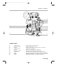
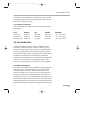
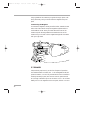
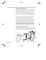
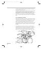
USER 16 US.sept
6/12/97 17:28
Page 1
prod
XTR
User’s Guide
Sept 96
USER 16 US.sept
6/12/97 17:28
Page 2
USER 16 US.sept
6/12/97 17:28
Page 3
INTRODUCTION
This manual contains the handling, care and operating
instructions for the Aaton 16mm XTRprod camera and its
peripherals. Also included are chapters dedicated to the Super16
widescreen format and AatonCode, Aaton’s patented in-camera
timecode system.
Aatonomics
In keeping in line with the budget-conscious nature of 16 and
Super16 production, Aaton offers three camera models - X0plus,
XTRplus and XTRprod.
Each model is equipped with features specifically geared for certain
levels of production in order to help the user balance cost with his
or her particular needs.
All camera models are built of the same mechanical construction
and are identical with regards to size and weight, speed range,
image steadiness, noise level and durability. Keep in mind that the
differences between models is limited strictly to camera features.
The XTRprod is Aaton’s high-end model and is designed to offer
features such as Super16, AatonCode, internal lightmeter and
integrated CCD assist combined with new, state-of-the-art studio
features such as Aatonite illuminated viewing system, built-in
crystal speed control in .001 increments, multi-position shutter, a
full function illuminated LCD control panel and quick setting jog
wheel.
3
USER 16 US.sept
8/5/97 17:14
Page 4
AATON XTRprod User Guide
This manual has first been written by Peter Abel - ABELCINE TECH AATON
2 rue de la Paix
38000 Grenoble
FRANCE
(33) 4 7642 9550
(33) 4 7651 3491 fax
(c) june 1997 Aaton / Grenoble , France.
All rights reserved. No part of this manual may be reproduced or transmitted in any form or by
any means, electronic, mechanical, photocopying, recording, or otherwise, without the prior permission of the publisher. For more information please contact Aaton.
Limitation of Liability
The information contained in this manual is distributed without warranty of any kind, express or implied. To the maximum extent permitted by law, Aaton and its licensors disclaim any and all warranties, express or implied, by statute or
otherwise, regarding this manual, including the fitness for a particular purpose, quality, or merchantability. Under no circumstances shall Aaton or its licensors be liable to the user of this manual or any other person for any incidental, special,
or consequential damages resulting from the use of this manual or the operation of the equipment described therein,
whether arising out of breach of warranty, breach of contract, or otherwise. Under no circumstances shall Aaton or its licensors be liable for any damages arising out of the operation of the equipment described in this manual, whether operated in a manner which is consistent with or contrary to the instructions contained therein, for physical abuse or misuse of
the equipment. No oral or written information or advice given by Aaton or its licensors, their respective employees, distributors, dealers, or agents, shall create any warranty. Aaton and its licensors further disclaim any and all warranties, express
or implied, by statute or otherwise, regarding this manual, including the fitness for a particular purpose, quality, or merchantability, regarding the equipment described in this manual, and in no event shall Aaton or its licensors be liable for
any damages, including but not limited to incidental, special, or consequential damages, arising out of the use of the
equipment, or any exposure of motion picture film used in the equipment.
4
USER 16 US.sept
6/12/97 17:28
Page 5
TABLE OF CONTENTS
1
SYSTEM FEATURES AND CONTROLS
Front View
Rear View
Battery Side
Motor Side
LCD Control Panel - Quick Reference
2
12
13
14
15
16
THE CAMERA BODY
2.1 Lenses
ArriPL Lens Port
Installing the Lens
Aaton Lens Port
2.2 Viewing System
Viewfinder Options
Attaching the Extension Finder
Viewfinder Tension Adjustments
Adjusting the Diopter
The Eyepiece Shutter
Adjusting the Viewing Horizon
Viewing Screen
Changing the Viewing Screen
Adujsting the Viewing Screen
Aatonite Illumination
2.3 Mirror Shutter
Concept
Adjusting the Shutter
2.4 Film Gate and Pulldown Claw
2.5 Flange Focal Distance Adjustment
Concept
Polishing a Spacer
Changing the Spacer
Adjusting the Viewing Screen
Flange Focal Distances
2.6 Magazine
Installing the Magazine
Removing the Magazine
2.7 Power
20
20
20
21
21
21
22
22
23
24
24
24
25
26
27
27
27
28
29
29
29
30
30
30
30
31
31
32
33
5
USER 16 US.sept
6/12/97 17:28
Page 6
Installing the Battery on the Camera
Battery Charging
Other Power Options
2.8 Motor
Camera Speeds
Using External Speed Devices
Electronic Inching
2.9 Lightmeter
Display
Operation
Using the Lightmeter without Running Film
Testing and Adjusting the Meter
Turning the Lightmeter Off
2.10 LCD Control Panel and Jog
The Aaton Jog
Understanding the Control Panel
Aatonite
AatonCode
ASA Setting
Battery Voltage
Camera Preset Speed
Camera Specific Speed
Speed Phasing
Feet or Meters
Footage Remaining
Footage Elapsed
Mag ID
New Magazine’s Footage
Camera Software Version Number
2.11 LED Indicators
Position and Meaning of the Diodes
Camera Test Indicator
Camera Run Indicator
Low Battery Indicator
End-of-Film Warning Sequence
8-hours Warning Sequence
2.12 CCD Assists
Installing the Control Unit
The Internal Beamsplitter
Positioning the Beamsplitter
6
33
33
34
35
35
36
36
37
37
38
38
38
38
39
40
40
41
41
41
42
42
42
42
43
43
43
43
44
44
44
44
45
45
45
45
46
46
46
47
47
USER 16 US.sept
6/12/97 17:28
Page 7
TABLE OF CONTENTS
The Beamsplitter Axis Adjustment
The Manual Iris
Battery Life with CCD Assists
Installing the CCD Heads
The VR46 Color CCD Assist
Menu Operation
3
THE MAGAZINE
3.1 Concept
3.2 Compatibility
DX Magazines
Super16 Safe
3.3 Pressure Plate System
The Picture Plate
The Claw Plate
3.4 Mag Identification System
Mag ID
Changing the ID of a Magazine
3.5 Loading
Feed Side - In the Changing Bag
Take-up Side - In Daylight
4
48
48
49
49
52
53
60
60
60
60
61
61
61
62
62
62
63
63
64
THE AATON SYSTEM
4.1 Camera Configurations
15mm Front Rods
Sliding Bridgeplate
4.2 Handgrip
Mounting the Handgrip
Handgrip On/Off Functions
Handgrip Adjustments
4.3 Tripod Use
4.4 Shoulder Operation
4.5 Carrying Handle
3/8 Accessory Screw
Mounting from the Carrying Handle
Tape Measure Stud
68
68
68
69
69
69
70
70
70
71
71
71
71
7
USER 16 US.sept
6/12/97 17:28
Page 8
4.6 Transport
4.7 Extreme Conditions
Cold Weather
Warm Weather
5
CLEANING
5.1 Lens
Lens Elements
Lens Exterior
Mounting Surface
5.2 Body
Exterior
Mounting Surfaces
Camera Gate
5.3 Viewing System
Viewing Screen
Eyepiece
Viewfinder
5.4 Magazine
Exterior
Pressure Plates
Interior / Film Path
6
78
78
78
78
78
78
79
79
79
79
80
81
81
81
81
81
SUPER16
6.1 Super16
The Format
When to Shoot Super16
6.2 General Concerns
Protecting the Negative
Maintaining High Quality
Film Processing
6.3 Shooting Super16
Selecting a Film Stock
Lenses
Lighting
Exposure
8
72
73
73
74
84
84
84
84
84
85
85
86
86
86
86
86
USER 16 US.sept
6/12/97 17:28
Page 9
TABLE OF CONTENTS
6.4 Super16 Field Conversions
Before You Begin
Procedure
7
AATONCODE
7.1 Concept
7.2 The Internal Clock
7.3 OriginCplus
7.4 Initializing AatonCode in the Camera
Using the OriginCplus - Recommended Method
Using an External SMPTE Device
7.5 Monitoring and Maintaining AatonCode
Monitoring AatonCode with OriginCplus
Maintaining AatonCode without OriginCplus
7.6 GMT1
7.7 The Camera Assistant's Duties
Checking the Diodes
Setting the ASA
Checking for Running Time
8
96
96
97
98
98
99
99
100
100
100
101
101
102
102
TECHNICAL SPECIFICATIONS
List of Specifications
Connector - Pin Attributions
Available Viewing Screens
9
87
87
88
106
107
108
WORLDWIDE SUPPORT
Worldwide support
112
9
USER 16 US.sept
6/12/97 17:28
Page 10
USER 16 US.sept
6/12/97 17:28
Page 11
1
SYSTEM FEATURES AND CONTROLS
11
USER 16 US.sept
6/12/97 17:28
Page 12
1
2
3
8
9
4
10
5
6
7
1.1 FRONT VIEW
1
2
3
4
5
6
7
8
9
10
12
Friction Adjusting Ring
Tape Measure Stud
Lateral Lock Knob
Beamsplitter Access Cap
CCD Cover
PL Lens Port
Wooden Handgrip
Eyepiece Lock Ring
Eyepiece Shutter
Body Run/Test Switch
adjusts the tension of the eyepiece swivel.
holds tape measure at film plane.
locks the lateral position of the viewfinder.
covers the port which accesses the beamsplitter adjustment screw.
accesses the CCD head.
standard mounting system for XTRprod.XTRprod.
allows for comfortable handheld operation.
fastens interchangeable standard and extension finders.
blocks light when operator's eye is away from the finder.
provides camera run and half frame inching.
USER 16 US.sept
6/12/97 17:28
Page 13
GENERAL OVERVIEW
13
14
15
11
16
12
17
18
19
20
1.2 BACK VIEW
11
12
13
14
15
16
17
18
19
20
Magnetic Drive
Mag Release Lever
Amph9
Manual Iris Lever
Lemo14
Battery Lock Screw
Camera Fuse
XLR4
Lemo8
Lemo6
provides magnetic magazine coupling.
releases the magazine for removal.
accessory input provides +/-, Hz, and camera run functions.
controls CCD iris operation.
connects CCD head to the CCD control unit.
fastens the on-board battery to the camera body.
protects the body from excessive current and reverse polarity.
main power input for on-board battery or other 12V power source.
accessory input provides +/-, Hz, TVsync, 100PPF and camera run.
accessory input provides +/- and camera run functions.
13
USER 16 US.sept
6/12/97 17:28
Page 14
21
26
27
22
23
28
24
29
25
30
1.3 BATTERY SIDE
21
22
23
24
25
26
27
28
29
30
14
CCD Control Unit
CCD On/Off
Carrying handle
Diopter Set Ring
Run/Test Switch
Take-up Latch
On-board Battery
LED Indicators
Lemo2
Adjusting Screw
fastens to the body for CCD operation.
powers the CCD assist. Switch off to conserve battery life.
includes tape measure stud, 3/8-16 accessory hole and adjusting tools.
adjusts the diopter setting of the viewfinder to the operator's eye.
provides camera run and full frame inching from the handgrip.
locks the magazine take-up door.
12V nicad for handheld operation.
battery side indicators for camera run, camera test and low battery.
input provides camera run functions.
adjusts the rotation of the handgrip.
USER 16 US.sept
6/12/97 17:28
Page 15
GENERAL OVERVIEW
31
33
34
35
36
37 38
32
39
40
1.4 MOTOR SIDE
31
32
33
34
35
36
37
38
39
40
LCD Control Panel
Carrying Handle
Lemo5
Lightmeter On/Off
LED Indicators
Motor
Aaton Jog
AatonCode Led
Feed Latch
Mag Footage Counter
displays AatonCode, ASA, speed, voltage, remaining footage.
includes tape measure stud, 3/8-16 accessory hole and adjusting tools.
AatonCode and SMPTE timecode communication.
activates the lightmeter display in the viewfinder.
motor side indicators for camera run, camera test and low battery.
triphase salarium, low power consumption. 3-75 fps operation.
provides quick adjustment of Aatonite, ASA, speed, phasing, footage.
flashes each second if the timecode has been initialized in the camera.
locks the magazine feed door.
displays the footage remaining in the magazine feed side.
15
USER 16 US.sept
6/12/97 17:28
Page 16
1.5 LCD CONTROL PANEL - QUICK REFERENCE
SET
Show
SYNC
Fps/Ft
EX/VAR
time
ISO
batt/iso
MAG
Elapse
IN SHOW MODE
24’ - 080
ISO = 100
Batt = 10’4
Ela = 042
22=32=54
95-03-25
123456
2321
Camera speed and Remaining footage
Film ASA
Battery voltage
Elapsed footage during last take
Hours=minutes=seconds in AatonCode
Year-Month-Day in AatonCode
Production ID in AatonCode
Equipment number in AatonCode
(default mode)
(1 x Batt/Iso)
(2 x Batt/Iso)
(2 x Speed)
(1 x Time)
(2 x Time)
(3 x Time)
(4 x Time)
IN SET MODE
Sp =2 4’
Sp = 27’454
Et
Phase
ISO = 100
MAG = 400
MAG = 140
Adjusting a preset speed
(SET, 1 x SYNC, toggle SYNC or use Jog)
Adjusting a specific speed
(SET, 1 x VAR, use Jog)
Speed controled by external speed device
(SET, 2 x VAR)
Phase Adjusting
(Camera running,SET, 2 x VAR, use Jog)
ASA Setting
(SET, 1 x ISO, toggle ISO or use Jog)
Indicating that the new magazine is fully loaded
(SET, 2 x MAG)
Indicating the new magazine's footage
(SET, 1 x MAG, use Jog)
WARNINGS
Lo Spd
Lo Batt
Empty
Unadjust
16
Camera has not yet reached the selected speed
Battery is too low (below 10V)
No more film in the magazine
Please check page 39
USER 16 US.sept
6/12/97 17:28
Page 17
GENERAL OVERVIEW
17
USER 16 US.sept
6/12/97 17:28
Page 18
USER 16 US.sept
6/12/97 17:28
Page 19
2
THE CAMERA BODY
19
USER 16 US.sept
6/12/97 17:28
Page 20
2.1 LENSES
The XTRprod’s flexible lens mounting system allows for the use of a wide
variety of 16mm, 35mm and still-photographic lenses.
Flange focal distance
Refers to the critical distance
from the lens seat to the film
plane. The precise FFD of the
XTRprod is 52mm -6 to 15µm as measured with a
depth gauge in the lens port. It
is recommended that these
tolerances be checked and
maintained by a qualified
technician. The combination
of FFD and back focus
distance of a lens directly
affects precise focus and overall
image sharpness. Make sure
these critical measurements are
strictly upheld. When using an
unfamiliar lens for the first
time, check that the eye focus
matches the tape-measured
focus marks of the lens, and /
or shoot a focus test.
2.1.1 ArriPL Lens Port
The ArriPL lens port is the standard mounting system delivered
with the XTRprod and allows the use of all 16 and 35mm ArriPL
mounted motion picture lenses. PL lens adaptors are available for
Arri standard and Arri bayonet mounted lenses. This mount is ideal
for rental facilities, where a mounting system compatible with other
manufacturer’s 16 and 35mm cameras is often desired. The specific
flange focal distance (FFD) of the XTRprod with PL port is 52mm
-6 to -15µm.
2.1.2 Installing the Lens
To install the lens on the camera body, turn the outer locking ring
counter-clockwise until it reaches its stop. If the port cap is on,
remove it. Align the four protruding flanges on the lens with the
four corresponding cutaways in the locking ring and insert the lens
into the camera port so that its flanges rest evenly against the lens
seat. Tighten the locking ring by turning clockwise until the lens is
secured in place and the lock ring is firmly set. Make sure the lock
20
USER 16 US.sept
6/12/97 17:28
Page 21
THE CAMERA BODY
ring is tight enough so that it cannot be inadvertantly unlocked.
2.1.3 Aaton Lens Port
The XTRprod can also be equipped with an Aaton lens port. In
order to install the Aaton port, the ArriPL lens seat and locking ring
must first be removed.
Because the FFD of the Aaton lens port is shorter than most
professional cameras (40mm), the XTRprod, equipped with this
mount, can accommodate most motion picture and still camera lens
mounts. Lenses can be used equipped with an Aaton mount or by
adapting another manufacturer’s lens mount. Aaton lens adaptors
are available for Arri standard, Arri bayonet and Eclair CA-1, as well
as Nikon and Leica-R photographic mounts.
2.2 VIEWING SYSTEM
2.1 Viewfinder Options
The viewfinder is designed to be fully orientable, providing left or
right side viewing and an upright image in any position.
The viewfinder is equipped with a standard short eyepiece that can
be used for handheld and tripod-mounted operation. For more
comfortable tripod and studio applications, the standard extension
finder can be fitted in place of the short eyepiece. With an Elemak
or Mitchell type dolly, or in situations requiring additional reach,
The Pechan prism
In order to provide a fully
orientable upright image, the
Aaton viewfinder incorporates
a pechan prism assembly,
which is actually comprised of
two triangular prisms
sandwiched together. On some
viewfinders, depending on the
construction of this prism,
rotation of the eyepiece a full
360° will cause the image in
the finder to shift slightly left
or right.
After attaching an extension
finder, if the image in the
finder appears to have shifted
slightly, rotate the finder 360°
and choose the preferred
centered image.
21
USER 16 US.sept
6/12/97 17:28
Page 22
the hyperlong finder, which is twice as long as the standard
extension finder, can be used.
Note that standard short eyepiece can now be equipped with a
heating system; in order to avoid any condensation on the eyepiece
lens. Aaton can provide you a heating lens and the corresponding
Amph9 cable.
2.2.2 Attaching the Extension Finder
In order to use an extension finder on the XTRprod, the standard
eyepiece must first be removed. To remove the eyepiece, locate the
eyepiece lock ring, marked A in the photo below. Rotate counterclockwise and gently pull off the eyepiece. To install the extension
finder, locate the protruding guide pin on the seat of the viewfinder
and align the pin with the hole in the flange of the finder. Mate the
flange to the seat of the viewfinder and tighten the lock ring until it
is set firmly in place. During this procedure, you will notice that the
extension finder needs to face 180° away from the operator’s eye to
be installed onto the viewfinder. Because of its optical construction,
this is completely normal. After installation, rotate the finder 180°
to regular viewing position.
2.2.3 Viewfinder Tension Adjustments
The large knurled knob at the base of the left/right lateral
movement point (b) locks the lateral positioning.
The friction adjusting ring, located behind the eyepiece lock ring,
can be used to adjust the tension of the eyepiece swivel, depending
on the operator’s preference and the viewfinder being used. When
using the standard eyepiece, tension should be relatively light to
allow for movement with a moderate amount of pressure. When
using the standard extension finder, tension should be increased to
hold the additional weight of this finder in place.
To adjust the tension of the swivel, loosen the steel knurled screw (c)
located on the friction adjusting ring. Hold the eyepiece in place,
22
USER 16 US.sept
6/12/97 17:28
Page 23
THE CAMERA BODY
d
c
b
a
rotate the adjusting ring slightly and retighten the screw; 1/8 of a
turn, at first, will have an effect. To increase tension of the eyepiece
swivel, rotate the adjusting ring clockwise; to decrease the tension,
rotate the adjusting ring counter-clockwise.
2.2.4 Adjusting the Diopter
Before shooting, the diopter setting of the viewfinder should be
adjusted to the operator’s eye. To set the diopter, locate the diopter
set ring (d) in front of the carrying handle at the top of the
viewfinder, and loosen the small knurled knob. Look through the
viewfinder, rotate the diopter set ring until the edge of the cross-hair
is at its sharpest point and retighten the knob. It is recommended
that, for easiest setting, this adjustment be performed with the port
cover off and no lens on the camera.
Notice that the diopter set ring is engraved with numbers and dots use this reference to quickly recall your particular setting when more
than one person will be looking through the view-finder.
The range of the diopter setting is + or - 3. If the range does not
reach your particular diopter setting, the viewfinder optics can
quickly be adjusted by a qualified technician and the diopter range
reset to meet your needs.
2.2.5 The Eyepiece Shutter
In order to avoid unwanted light seepage through the viewfinder,
23
USER 16 US.sept
6/12/97 17:28
Page 24
the eyepiece shutter must be closed any time the camera is running
film and the operator’s eye is away from the viewfinder.
To close the eyepiece shutter on the standard bellows eyepiece, grasp
the rubber ring at the base of the eyecup and rotate 1/8 of a turn
counterclockwise. On the extension finder and the old style standard
eyepiece, locate the small tab at the base of the rubber eyecup and
slide it until the shutter completely covers the eyepiece opening. On
the hyperlong finder, rotate the knurled ring closest to the eyecup
counter-clockwise to close the shutter.
Checking your Viewing
Horizon
here is a simple means of
determining whether
adjustment of the horizon
needs to be made. Mount a
zoom lens onto the camera and
rest the camera on your
shoulder in a standard
handheld position. Look
through the viewfinder with
your right eye while also
keeping your left eye open.
Compose a frame that includes
vertical or horizontal lines (a
window frame, for example)
and adjust the zoom of the lens
so that the focal length of the
lens generally matches what
you see with your left eye.
Ignore the viewing screen
markings for the time being
and determine whether the
rotation of the image you see
through the viewfinder
matches what you see with
your left eye. If it does not,
then a fine adjustment may be
necessary
24
.2.2.6 Adjusting the Viewing Horizon
If the rotation of the image seen through the cameras viewfinder
does not exactly match what is seen through the naked eye, there is
a fine adjustment that can be made to the image’s relative horizon.
Locate the small slotted screw located on the underside of the
viewfinder just inside the eyepiece lock ring. Notice that the screw
travels in an elongated cutout. Loosen the screw one turn and, while
looking through the viewfinder, move the screw within its cutout in
order to adjust the horizontal rotation. When the images seen
through your left and right eyes coincide, lock the screw.
2.2.7 Viewing Screen
The unique concave design of the Aaton fiber optic viewing screen
gives it its superior sharpness and lucid quality. If your viewing
screen possesses a dark blemish or two, don’t be alarmed; these spots
are actually fractured fibers and are inherent in the manufacturing of
fiber screens. Such blemishes, although occasional, are the trade-off
for the brilliant screens which result from the use of this technology.
The XTRprod utilizes an interchangeable viewing screen system
which allows the cinematographer to install the screen which best
suits his particular application(s). Aaton offers eleven viewing
screens as standard. (see the Technical Specifications chapter)
Specially marked screens can also be manufactured to order. Contact
you local Aaton representative for details.
Unlike the XTRplus, which uses a universal screen that shifts
USER 16 US.sept
6/12/97 17:28
Page 25
THE CAMERA BODY
between std 16 and Super16 operation, the XTRprod requires
separate screens for std 16 and Super16 formats.
2.2.8 Changing the Viewing Screen
The viewing screen is designed to be easily removed by the user for
the purposes of interchanging or for cleaning. To remove the screen,
unscrew the black tool marked Vw located in the hollow at the rear
of the camera’s carrying handle. Remove the port cap. Clear the
mirror shutter so that it is rotated safely inside the body by rotating
at the base of the shutter with your finger or by setting the camera
to test position, then removing the battery. Look into the port and
locate the threaded hole directly above the aperture opening and
screw in the tool until it is snug. Carefully pull the screen straight
out.
To reinstall the screen, screw the Vw tool into the threaded hole of
the screen until it is snug. Look into the port and locate the left and
right lip of the viewing screen holder. With its flat side facing down,
gently push the screen straight into the holder above the lip until it
seats firmly in place. Unscrew the Vw tool and store back in the
hollow of the carrying handle. Reaffirm that the screen is seated
properly by carefully pressing against the threaded hole with your
thumb.
25
USER 16 US.sept
6/12/97 17:28
Page 26
Attention !
Each time you're touching the
mirror, the viewing screen, or
anything inside the lens port,
disconnect the battery. You
will therefore avoid any risk of
seriously damaging your
camera.
2.2.9 Adjusting the Viewing Screen
The image on the viewing screen should be sharp, and its focus
should match to that of the film. This can be best determined with
the use of a collimator, or by looking through the viewfinder and
checking that the sharp focus of a lens matches the measured
distance on its barrel. If it does not, then you need to make an
adjustment of the viewing screen focus.
To proceed, you must first unscrew and remove the circular cap
located on behind the camera boy Run/Test switch.Inside the access
hole, inser a 2mm Allen wrench and screw or unscrew it. Replace
the circular cap. Use a collimator to check that you have reached the
sharpest focus of the viewing screen image. If the image is not yet
sharp ennough, proceed again.
2.10 Aatonite Illumination
The XTRprod features illuminated viewing screen markings referred
to as Aatonite. The level of illumination is adjustable by the user via
the Jog wheel, which is located to the right of the motor. To operate
Aatonite, power the body and switch the run/test switch to test
position and off again to turn on the camera electronics. Look
26
USER 16 US.sept
6/12/97 17:28
Page 27
THE CAMERA BODY
through the viewfinder and rotate the jog to set the desired level of
illumination. The markings will remain illuminated for a full 2
minutes after the camera is set in the off position. The illumination
level set in test position will be memorized and recalled once the
camera is run. The illumination level can also be readjusted while
the camera is running.
The configuration of illuminated markings will differ slightly
between screen types. Refer to the screen illustration on page 21 for
a specific description of each screen type along with its
corresponding Aatonite markings.
2.3 MIRROR SHUTTER
2.3.1 Concept
The reflex mirror shutter is designed to provide an optical path to
the viewfinder while the claw movement advances the film to the
next frame.
The shutter features a four-position user-adjustable opening:
• Standard 180° for filming
under standard 60 Hz HMI lighting at 24 fps _or_
under standard 50 Hz HMI lighting at 25 fps without flicker
• 172.8° for filming
at 24 fps under 50 Hz HMI lighting without flicker.
• 150° for filming
at 25 fps under 60 Hz HMI lighting without flicker.
• 144° for filming
to minimize the roll bar while filming an NTSC broadcast
monitor at 24 fps.
2.3.2 Adjusting the Shutter
To adjust the shutter opening, unscrew the blue shutter tool marked
Sh located in the hollow at the rear of the camera’s carrying handle.
Make certain that the battery is off the camera and remove the port
cap. Locate the tool guiding hole to the lower right of the inside of
27
USER 16 US.sept
6/12/97 17:28
Page 28
the lens holder (see diagram). Gently rotate the shutter at its base
with your finger until the brass driving gear is centered underneath
the tool guiding hole. Insert the shutter tool through the guiding
hole and into the brass gear. Rotate the tool until the appropriate
notched shutter setting is reached; turning counterclockwise will
reduce the shutter opening, turning clockwise will increase the
opening.
When setting the opening to 172.8° or 144°, a shutter blade
indicating these settings will be visible from behind the left edge of
the mirror. Make sure the white line to the immediate right of the
172.8° and 144° markings meet the left edge of mirror.
When the adjustment is complete, remove the tool and store back in
the hollow of the carrying handle.
Sh
2.4 FILM GATE AND PULLDOWN CLAW
2.4.1 Co-planar Movement
All Aaton cameras incorporate a patented means of advancing the
film called a co-planar claw movement. By utilizing this technique,
28
USER 16 US.sept
6/12/97 17:28
Page 29
THE CAMERA BODY
Aaton is able to achieve an ultra-precise pulldown with a minimal
number of moving parts. The co-planar concept is the key to the
camera’s low-noise operation.
The film gate also features a side pressure bar which is recessed into
the claw-side rail at the point of image exposure to assure maximum
lateral stability.
This unique, straight forward mechanism design results in
horizontal and lateral film registration that is superior to all other
16mm camera movements with an accuracy of 1/2000 of the image
dimensions.
4.2 The Hair-Free Gate
In most 16mm camera designs, there is a certain amount of film
dust (also referred to as fluff or hair) that is generated as film rolls
through the magazine and enters the camera gate. Because the gate
and pulldown are the areas where the film must be held most rigidly,
these are also the areas where most of the accumulating film dust
tends to be deposited. The result could be a visible hair in the
picture area and an unuseable shot.
Aaton has taken steps in the design of their magazines and gate
assembly to ensure hair and dust-free images. The Aaton magazine
features a twistless film path with little sprocket contact, which
minimizes the amount of film dust that builds up before entry into
the aperture area.
4.3 Cleaning the Gate
In order to avoid film dust buildup in the recessed channels of the
gate, the gate should be inspected during magazine changes and
cleaned every three to four mags if the shooting schedule permits.
Refer to the Cleaning chapter for more detailed information.
2.5 FLANGE FOCAL DISTANCE
ADJUSTMENT
2.5.1 Concept
29
USER 16 US.sept
6/12/97 17:28
Page 30
For a few years now, Aaton has inserted a spacer between the lens
port and the camera body. This thin (0.3mm) metallic ring is
responsible for the precise distance between the lens port seat and
the film plane called the flange focal distance (FFD), and therefore it
is also mainly responsible for the sharpness of the images.
Anyone who would like to change the FFD of his own camera
should now do so by simply changing the spacer, and only with the
spacer. He has not to polish any other surface, ot to insert anything
else between the lens port and the film plane. For that purpose, you
can order some aluminium spacers (0.35mm) to Aaton, and then
safely change the FFD of your camera.
2.5.2 Polishing a Spacer
In order to fine-adjust the thickness of a specific spacer, Aaton
carries a specific tool (ref 35 310 32) designed to hold the spacer
firmly and evenly against Emery paper. When polishing a spacer,
always work on a perfectly flat worktable or stone, and be sure to
hold the tool firmly.
2.5.3 Changing the Spacer
The spacer is placed between the lens port and the camera body’s
titanium lens holder. If you’re camera is equipped sith a PL lens
port, you first need to remove the lens locking ring: screw two or
three turns its stop (placed on the bottom, inside the PL port), and
turn the ring counterclockwise.
Remove the lens port by unscrewing its screws. Then remove the
aluminium spacer gently.
Once you have placed a new spacer, replace the lens port, then the
lenses locking ring. Do not forget to unsrew two or three turns the
locking ring stop, if you have a PL lens port.
2.5.4 Adjusting the Viewing Screen
Because you have changed the distance separating the base of the
lens and the camera body, the image on your viewing screen might
30
USER 16 US.sept
6/12/97 17:28
Page 31
THE CAMERA BODY
now appear to be less sharp than usual. Most likely, you may need
to readjust the precise focus of the viewing screen. Refer to the 2.9
section of this chapter to proceed.
2.5.5 Flange Focal Distances
Here are the flange focal distances for all the lens port available for
the XTRprod.
Mont
Aaton (AA)
Arriflex (PL)
Panavision (PV)
Reference
01 112 35
01 113 20
01 113 25
FFD
40.00 mm
52.00 mm
57.15 mm
Diametre
50.00 mm
54.00 mm
49.50 mm
Adjustment
-40 / -50 microns
-60 / -70 microns
-40 / -50 microns
2.6 THE MAGAZINE
The Aaton magazine holds 400 ft (122m) of standard 16mm or
Super16 film. Shooting at 24 fps, a 400 ft roll will run for 10.5
minutes; shooting 30 fps, the same roll will run for approximately 9
minutes. The coaxial design of the magazine allows for complete
self-contained threading, quick mag changes and a minimal amount
of loading to be performed in the changing bag. Loading the
magazine is a simple operation that, with practice can be performed
in a little over a minute. Refer to the Magazine chapter of this
manual for complete details on loading and caring for magazines.
6.1 Installing the Magazine
The instant mag design allows for instantaneous switching between
mags on the set. To install the magazine on the camera, situate
yourself towards the rear motor side of the camera body. If the
aperture cover plate is on, remove it. Place your left hand around
the front of the camera just underneath the lens area. Grasp the
magazine firmly with your right hand below the midway point of its
rear. While holding the camera body with your left hand, guide the
magazine along the base of the camera into the aperture area. Make
sure that the top edge of the throat of the magazine is parallel to the
31
USER 16 US.sept
6/12/97 17:28
Page 32
carrying handle of the camera as you guide the mag in place. Push
firmly and evenly until you feel and hear the magazine snap into
place.
6.2 Removing the Magazine
To remove the magazine, situate yourself as before, towards the rear
motor side of the camera. Grasp the magazine anywhere which is
comfortable at its rear. Place your hand above the motor of the
camera and push the mag release lever towards the front of the
camera with your thumb. Pull the magazine straight off the camera
with your right hand.
2.7 POWER
XTRprod body requires only 12 volts for all aspects of operation.
One standard Aaton on-board (12V 1.7 ah rechargeable nicad) will
power the camera, CCD and any accessories which are connected to
the body’s accessory inputs (such as zoom controls, speed controls
etc.) through a standard 4 pin XLR connector. One 1.7 ah on-board
battery will run 7-8 magazines on the XTRprod, without CCD and
32
USER 16 US.sept
6/12/97 17:28
Page 33
THE CAMERA BODY
accessories. With accessories in use, this number will decrease.
2.7.1 Installing the Battery on the Camera
The on-board battery fits below the CCD control unit on the
battery side of the camera body. In order to install, loosen the black
knurled screw approximately four or five turns. Push the battery
evenly onto the XLR4 connection on the body. When snug, tighten
the knurled screw onto the battery tab to hold it in place.
When running AatonCode, get into the practice of having a fresh
battery on hand before removing the one from the camera. Even a
low battery that no longer runs the body (below 10V) will have
enough voltage to keep accurate time counting.
Thanks to a super capacitor built into the camera base, you will
have a full minute to change the battery before time is lost. After
replacing the battery, confirm that time is still counting by looking
for the yellow blinking diode to the right of the motor or checking
the control panel.
2.7.2 Battery Charging
The Aaton on-board can be recharged with an appropriate 12V
nicad battery charger.
For the best results, use a microprocessor-controlled charger or a
standard trickle charger with a charging output of at least 200ma,
both of which prevent the overheating and mistreatment of your
nicad cells. Always follow the specific guidelines of the charger
manufacturer. You can use the Aaton Chr1, designed to charge two
standard batteries in 6 hours, without any risk.
Beware of older, timed chargers manufactured when 1.2 and 1.4ah
batteries were the norm; these chargers were most likely rated for the
lower amperage batteries of that time and will consistently
undercharge the higher rated nicad cells of today.
2.7.3 Other Power Options
Since the XTRprod power input is a standard 4pin XLR type, a
great variety of 12-14 volt sources can be used to power the camera.
33
USER 16 US.sept
6/12/97 17:28
Nicad Batteries Tips
Follow a few simple rules to
insure the long life of your
nicad cells:
• Allow batteries to run
through their normal cycle of
charging and use. Avoid
topping off partially full
batteries. Once every few
months, discharge cells to 810V using a standard
discharger to minimize their
memory.
• Do not rapid-charge your
cells more than necessary, as
the added heat will eventually
shorten their life span.
Instead, recharge batteries at a
normal charging rate when
your schedule allows.
• If your batteries will not be
used for long periods of time,
always store them in a cool,
dry environment fully charged.
Page 34
This includes AC power supplies, battery blocks, lithium cells and
car batteries.
Get into the habit of carrying a standard XLR4 powercable in your
package in case an alternative power source is needed.
Regarding AC power supplies, it is recommended that the unit you
use be at least 4 amps and 25 watts. Before connecting any nonstandard source, always make sure that the pin configuration of the
unit is correct. See the Technical Specifications chapter of this
manual for details for proper wiring.
2.8 MOTOR
The tri-phase samarium motor design of the XTRprod provides low
power consumption and improved stability at high speeds. The body is
capable of speeds between 3 and 75 fps with a standard 12V battery.
2.8.1 Camera Speeds
The XTRprod provides boths preset crystal speeds (in sync mode)
and specific crystal speeds (in variable mode) in .001 increments, all
accessible from the LCD control panel.
Available preset speeds consist of 6, 12, 18, 20, 23.98, 24, 25,
29.97, 30, 36, 40, 48, 60 and 75 fps. The preset speed selector
(SYNC) allows for quick access to these frequently used speeds.
If any other speed is desired, or if the camera speed must match the
frequency of a monitor to eliminate a roll bar, the specific speed
selector (EX/VAR) should be employed. The specific speed selector
34
USER 16 US.sept
6/12/97 17:28
Page 35
THE CAMERA BODY
enables the body to run at any speed between 3 and 75 in .001
frame increments. A phase adjustment of the variable speed is
accessible from the EX/VAR selector.
The camera speed can also be adjusted while the camera is running
in either sync or variable mode. For more information on these
speed functions, refer to section LCD Control Panel and Jog of this
chapter.
2.8.2 Using External Speed Devices
The XTRprod can be driven externally from devices such as
film/video synchronizers, speed aperture computers and external
speed controls. In these situations, the camera EX/VAR selector
must be set to et. If such a device is connected and the selector is
not set to et, the camera will run at the speed indicated on the
display.
Keep in mind that, with certain manufacturer’s speed controls, it
may be possible to run the camera at speeds higher than the 75 fps
factory limitation. Overcranking in such a way, however, will
increase mechanism wear, increase noise and compromise image
registration. Aaton urges to avoid such usage at all cost and will not
be responsible for the resulting damage that may occur. This top
speed cap of 75 fps has been designated by Aaton because it is the
level at which the camera can run safely without any adverse effects
on its mechanics.
2.8.3 Electronic Inching
The inching function of the motor is accomplished electronically
and can be accessed in a number of ways.
•From the Body
The large run/test switch on the motor side of the body, not only
runs the camera, but provides half frame inching for gate inspection,
lightmeter functions and loop situating when installing a fresh mag.
From the Handgrip
The wooden handgrip switch, by way of the Lemo2 connector,
provides camera run and full frame inching for single frame
35
USER 16 US.sept
6/12/97 17:28
Page 36
operation and loop situating.
•From a Remote Cable
The Lemo2 connector, as well as Lemo6, Lemo8 and Amph9
accessory connectors, provide the capability of using a remote on/off
with either a half-frame or full-frame inching function.
2.9 LIGHTMETER
The XTRprod is equipped with an internal lightmeter that is
designed to read the quantity of light reflected off the film itself. For
added accuracy, the meter measures the light by means of two
photocells. The metering system automatically compensates for
filters and changes in camera speed.
2.9.1 Display
Through the viewfinder, the lightmeter display is positioned directly
below the viewing screen across the bottom of the frame. A single
darkened diode moves across an array of 13 yellow and green diodes,
indicating proper exposure (see diagrams). Each diode represents
one third of a stop, while normal exposure darkens the center green
diode. Underexposure of -2 stops or more darkens the green diode
on the left end of the row; overexposure of +2 stops or more darkens
the green diode on the furthest right of the display.
To the immediate left of the display is the red diode indicator,
which has the same functions as the red diodes on the left and right
sides of the body. See section LED Indicators for further details.
2.9.2 Operation
Because the lightmeter takes its measurement as a reflection off the
film, you must have film in the gate for the camera to provide an
accurate reading.
To use the lightmeter, follow these simple guidelines: Set the ISO
selection on the control panel to the exposure index of the film
36
USER 16 US.sept
6/12/97 17:28
Page 37
THE CAMERA BODY
stock being used. Set the camera to run or test position and adjust
the lens iris until the center green diode is darkened; this will be
your proper metered exposure.
Remember, the lightmeter is giving you an average reading of the
entire frame. You may choose to vary the suggested exposure
according to subject conditions.
2.9.3 Using the Lightmeter without Running Film
It is also possible to use the lightmeter without actually running the
camera. Set the ISO selection to the exposure index of the film
being used. Set the camera to test position using the on/off switch
on the body or the handgrip. If the handgrip is used, the
momentary switch must be held in the test position. The mirror
shutter will rotate 180° allowing light from the lens to reach the film
and a reading to be taken by the meter. Adjust the lens iris until the
center green diode is darkened, indicating proper exposure.
Single Frame Operation
You may use the wooden
handgrip Run/Test switwh of
your camera to shoot a single
frame: just press this button to
Test and immediatly release it.
In that case, the filme is
exposed during 1/4 second.
But you need to know that the
XTRprod chamber is still not
opaque ennough so that more
than 10 minutes can separate
two single image shots. To use
an Aaton camera in single
image shooting, you'd better
use an intervalometer and a
lens shutter.
2.9.4 Testing and Adjusting the Meter
If you are operating the lightmeter for test purposes, don’t forget to
have film in the gate before taking a reading
The following is the procedure for checking and adjusting the
sensitivity reading of the lightmeter:
• 1 - Evenly light a standard 18% grey card.
• 2 - With a loaded magazine and lens on the camera, frame the
chart so that it completely fills the Super16 frame.
• 3 - With a properly calibrated handheld lightmeter, take a reading
of the grey surface and set the T stop of the lens accordingly.
• 4 - Switch the camera to run or test position and check the
position of the darkened diode. If the center green diode is
37
USER 16 US.sept
6/12/97 17:28
Page 38
darkened, the camera’s lightmeter is set correctly. If the darkened
diode is to the left or right, it is possible to adjust its reading.
• 5 - To access the lightmeter potentiometer, remove the complete
viewfinder by means of the four screws which mount it to the front
housing. Locate the hole between the two viewfinder screwholes on
the top motor side of the front housing. The white potentiometer
will be visible within this hole.
• 6 - With a small screwdriver, adjust the potentiometer slightly; 1/8
of a turn will have an effect. Rotating clockwise will correct an
overexposure and move the darkened diode to the left; rotating
counterclockwise will correct an underexposure.
• 7 - In order to check your adjustment, replace the viewfinder,
tighten the four screws and repeat the procedure from step 4. When
the reading through the camera matches your handheld meter, the
adjustment is complete.
2.9.5 Turning the Lightmeter Off
If the lightmeter is not being used, it may be turned off. The on/off
toggle switch is located on the operators side to the left of the
motor. Keep in mind, the red diode indicator and end-of-film
warnings will function whether the display is on or off.
2.10 LCD CONTROL PANEL AND JOG
2.10.1 The Aaton Jog
Located to the immediate right of the motor, the Aaton jog is a
small wheel designed to simplify many user functions. When used
in conjunction with the control panel, the jog allows quick
adjustment of some of the otherwise time-consuming parameters
(such as the setting of a precise 5-digit speed or a film short end)
2.10.2 Understanding the Control Panel
The LCD control panel consists of an illuminated display and five
buttons to access information (see diagram). The control panel
38
USER 16 US.sept
6/12/97 17:28
Page 39
THE CAMERA BODY
operates in two modes: Show and SET. To show a parameter
without adjusting, go directly to one of the four function buttons (1
through 4 in the diagram) to view relative information. To set a
parameter, first press SET, then go to the appropriate button.
Information is changed by either toggling that button or by rotating
the jog, depending on the parameter. Pressing SET afterwards (or
waiting for 7 seconds) will enter your selection.
Capped text ( SYNC, EX/VAR, ISO, MAG) refers to those
functions adjustable while in the SET mode; standard text (Fps/Ft,
time, batt/iso, elapse) refers to those functions accessible directly in
the default Show mode.
Note that, while viewing a Show function on the control panel, any
inactivity longer than 10 seconds will revert the display back to its
default mode (speed and remaining footage). As mentioned
previously, any break longer than 7 seconds while in SET mode will
automatically enter the last selection.
The following parameters can be accessed from the LCD control
panel in conjunction with the jog. For more concise information,
see the table in the System Features and Controls chapter of this
manual.
Adustment Tips
While adjusting the sensitivity
of the lightmeter, you may
wish to use your direct view of
the display through the body's
top cavity for reference. If so,
there are a few points to
remember:
• Because the image is inverted
without the viewfinder in
place, your adjustments will
move in the opposite direction
than what is seen through the
finder.
• Since the cavity is open, light
will enter through this
opening, making any reading
inaccurate by 1/3 to 2/3 of a
stop. Therefore, only use the
direct view of the display to
reference the number of diodes
adjusted. Always check your
final adjustment with the
viewfinder in place.
2.10.3 Aatonite
In its default mode, the Jog controls the level of Aatonite viewing
screen illumination from zero to full brightness.
2.10.4 AatonCode
As a standard feature, the XTRprod is equipped with the capability
of recording AatonCode in-camera time. Timecode information is
exposed onto the film by means of seven micro-diodes, which are
relayed, by means of fiber optics, into the gate above the claw to the
right of the aperture opening. These micro-diodes flash rapidly to
form the code as the film rolls through the gate between exposures.
For more elaborate information regarding the uses and functioning
of AatonCode, OriginCplus and other related devices, refer to the
AatonCode chapter of this manual.
39
USER 16 US.sept
6/12/97 17:28
Page 40
If AatonCode has been initialized in the camera, press button Time
to view timecode information. Toggling button Time will display
hour/minute/second, then year/month/day, then the six-digit
production ID, then the camera’s equipment #, in that order.
2.10.5 ASA Setting
When using the internal lightmeter and/or AatonCode in the
XTRprod, the ASA (ISO) setting must be adjusted to the exposure
index of the film stock being used. The ISO selector on the LCD
control panel provides settings between 25 and 1000 ASA.
With regards to the lightmeter, the setting on the ISO selector
dictates to the camera what the exposure should be for a particular
film stock. For AatonCode, proper ASA / ISO selection will insure
that the timecode matrix recorded on the edge of the film in the
gate will be exposed at an appropriate and useable level.
Press button Batt/Iso twice to view the ASA selection. To adjust the
ASA setting, press SET, then button Batt/Iso. Make your selection
between 25 and 1000 ISO by toggling Batt/Iso or by rotating the
jog wheel.
If the ISO selector is adjusted while the camera is in test or run
position, the correction will not take place until the next camera
start.
2.10.6 Battery Voltage
Press button 3 to read the voltage of the camera’s power source.
Notice that, if the camera is running and button 3 is pressed, the
control panel will read and display the voltage under load.
2.10.7 Camera Preset Speed
The default mode of the control panel will automatically display the
camera speed selection, whether it be in sync or variable mode,
when the camera is powered but not running. When the camera is
turned on, the actual running speed to the .01 frame is displayed.
To adjust the preset speed, press SET, then button SYNC. Make
your selection of stepped crystal speed between 6 and 75 fps by
40
USER 16 US.sept
6/12/97 17:29
Page 41
THE CAMERA BODY
toogling SYNC or via the jog wheel.
2.10.8 Camera Specific Speed
To choose a specific speed press SET, then EX/VAR. Make your
selection of any .001 incremented crystal speed between 3.000 and
75.000 fps via the jog.
To set the camera to be driven from an external source (such as
film/video synchronizer or external speed control), press SET, then
EX/VAR twice. Et will be displayed, indicating that camera is set in
external mode.
2.10.9 Speed Phasing
The phasing of the variable speed can be set to eliminate a roll bar
while filming a monitor. Operate first with no magazine on the
camera, because you first need to synchronise the camera speed to
the monitor frequency. Run the camera. Press SET, then EX/VAR
once, turn the jog, until the roll bar seems stable on the screen. Press
SET to enter. Stop the camera, and then install a magazine. Run
the camera. Press SET, then EX/VAR twice. Look through the
camera at the monitor and press EX/VAR until the roll bar is out of
view. Press SET to enter.
Force Processing and the
AatonCode matrix
Regardless of the situation,
always set the ASA selector to
the actual exposure index of
the film. If you know
beforehand that your footage
will be pushed or pulled, don't
worry about compensating for
the sake of the precise exposure
of your timecode matrix. The
matrix is resistant enough to
handle exposure variances of
one and a half stops or more in
either direction.
2.10.10 Feet or Meters
The control panel can be set to count in either feet or meters in the
following manner. Unplug power from the camera until the display
goes dark. Simultaneously press button MAG while plugging power
back in. Continue to hold button MAG and set camera Run/Test
switch to test position; foot or meter will show on the display.
Toggle button MAG to make your selection.
2.10.11 Footage Remaining
The control panel will display the memorized footage remaining any
time the camera is running with a magazine on.
41
USER 16 US.sept
6/12/97 17:29
Page 42
2.10.12 Footage Elapsed
With the camera stopped, press button MAG to view the elapsed
footage of the previous camera run. With the camera running, press
MAG to view the elapsed footage of that particular take. The
display will revert back to the default mode (speed and remaining
footage) after 10 seconds.
Changing Speeds while
Running the Camera
Any camera speed, wether
preset or specific, can be
changed when the camera is
running. To do so, run the
camera, then follow these
simple steps:
• Operating under a preset
speed (in sync mode), press
SET, then SYNC, then use the
jog wheel to choose a higher
or lower stepped speed.
Under a specific speed (in
variable speed), press SET,
then VAR, then use the jog to
ramp the speed higher or
lower in .001 frame
increments.
2.10.13 Mag ID
The XTRprod will recall the footage according to the mag ID,
which distinguishes seven magazines (A through G). To check the
ID of a particular mag, as read from the control panel, press button
MAG twice; the letter ID on the display should coincide with the
letter on the mag’s feed side door. For more information regarding
Mag ID, refer to the chapter entitled The Magazine.
2.10.14 New Magazine’s Footage
With a fully loaded magazine on board, press SET, then button
MAG twice to reset the control panel to count down a full 400 ft
load. If a short end is being used, press SET, then button MAG,
then reset the desired footage via the jog.
Note that the camera does not take a physical reading of the film
roll to determine the footage reading on its display; it is only a
counter and it must be set by the user. There is, however, a
mechanical footage counter on the magazine that automatically
measures the size of the camera roll; use the magazine footage
counter to determine the correct short end length to input on the
control panel.
2.10.15 Camera Software Version Number
If you need to know the software version number your camer is
equipped with, proceed as follow. Unplug the battery fron the
camera. Put the camera on Test mode. Then, while pluging back the
battery, watch carefully the LCD control panel. During one second
it will display something like: T4 U6.00, indicating the you own a
42
USER 16 US.sept
6/12/97 17:29
Page 43
THE CAMERA BODY
35mm 4-Perf camera, working with the software version number
6.00.
2.11 LED INDICATORS
The XTRprod utilizes LED indicators in three locations to convey
information: in the viewfinder and on both left and right outsides of the
camera body.
2.11.1 Position and Meaning of the Diodes
• Two yellow diodes, placed on both right and left sides of the
camera body indicate that the camera is either on Test or on Run
mode.
• Two red diodes, placed on both right and left side of the camera
body, and a third one, visible from the view finder, display a special
warning.
• One yellow diode, located to the right of the Jog wheel and called
the timecode diode, flashes each second if the timecode has been
initialized in the camrea.
Displaying a 5 Digit
Speed
If the XTRprod is set to a
variable (5-digit) speed, the
control panel will only display
that speed to the .01 digit.
Keep in mind, the display will
not rounf off the speed, but
simply leave off the last digit.
For example, if the 5 digit
speed of 23.976 is entered, the
control panel will display
23.97, not 23.98.
2.11.2 Camera Test Indicator
● Yellow diode is on.
● ❍ ● ❍ ● Red diode is blinking fast.
2.11.3 Camera Run Indicator
● Yellow diode is on.
❍ Red diode is off.
2.11.4 Low Battery Indicator
● Yellow diode is on.
● ❍ ❍ ● ❍ ❍ ● Red diode is flashing slowly.
The LCD control panel displays Lo Batt.
Remember…
Variable Speed for Phasing
Keep in mind, the speed phase
function of the control panel
will only operate when a
variable speed is initially
selected.
When shooting 29.97, for
example, be sure to choose the
specific 29.970 instead of the
preset 29.97 if you plan to
incorporate the phase function
for that particular shot.
43
USER 16 US.sept
6/12/97 17:29
Page 44
2.11.5 Low Speed Indicator
● Yellow diode is on.
● ❍ ● ❍ ● Red diode is blinking fast.
The LCD control panel displays Lo Speed.
2.11.6 End-of-Film Warning Sequence
The lightmeter display features pre-end-of-film and end-of-film
warnings for the operator.
Under normal operation, the lightmeter display will flash once for
every foot or meter that is counted down. When the footage counter
on the LCD control panel counts down to 10 feet remaining, the
display will flash more rapidly, at a frequency of about 2-3 times per
second. Keep in mind, the pre-end-of-film warning will only operate
if the lightmeter display is turned on.
When the counter reaches zero, the left and right sides of the display
will alternately flash, indicating the end of a roll. The end-of-film
warning will function whether the lightmeter display is on or off.
2.11.7 8-hours Warning Sequence
The timecode diode flashes slowly, everey 4 seconds, to indicates
that 8 hours have now been elapsed since the timecode was
initialized or controlled in the camera. You need here to re-initialize
or to control you camera timecode.
2.12 CCD ASSISTS
The Aaton VR42 black & white and VR46 color CCD taps are
designed to add video assist capability to the XTRprod without
compromising the body’s size, flexibility and ease-of-use. Because the
CCD head is incorporated into the XTRprod camera body, there are no
centering or focus adjustments necessary (unless, of course, when
converting the body between 16 and Super16 formats). The control
units for all Aaton CCD assists attach quickly to the camera’s PBX
housing and can be used with an on-board battery.
44
USER 16 US.sept
6/12/97 17:29
Page 45
THE CAMERA BODY
2.12.1 Installing the Control Unit
Both the VR42 and VR46 CCD control units can be easily attached
onto the XTRprod in a few seconds without the need for
adjustment.
Remove the two allen screws located on the PBX immediately below
the Lemo14 connector. Mate the Amph9 and Lemo14 connectors
of the control unit to those connectors on the body and plug in the
unit.
Replace the two allen screws to fasten the control unit; a third screw
of the same size should be screwed into the upper right side of the
unit from the opposite direction.
The control unit can remain permanently attached to the XTRprod
without adding discernable bulk or weight. Simply keep the unit
turned off and the beamsplitter retracted (see below) when video
assist is not needed.
2.12.2 The Internal Beamsplitter
The Aaton CCD assist system employs an internal, user-retractable
beamsplitter that reroutes a portion of the viewfinder's light path to
the CCD target while the video assist is in use. In situations which
do not require the CCD assist, the beamsplitter is designed to be
retracted to allow 100% of the viewfinder's light to reach the
eyepiece.
From body # 1928 and on, the beamsplitter delivered as standard
from the factory has a 75/25 reflection ratio. This means that 25%
of the light from the viewfinder is sent to the CCD target when the
beamsplitter is in place. This 75/25 ratio is ideal for use with
Aaton's VR42 black and white CCD. Although not visible from the
outside of the body, the 75/25 beamsplitter is identified by its blue
anodized holder.
Also available is a 50/50 beamsplitter, which sends a greater
percentage of light to the CCD target. This beamsplitter is
recommended for use with the VR46 color CCD and is
distinguished by its black holder.
45
USER 16 US.sept
6/12/97 17:29
Page 46
2.12.3 Positioning the Beamsplitter
The beamsplitter adjustment screw is located underneath a small,
capped port on the battery side of the camera. To access the
beamsplitter, unscrew and remove this silver cap. An allen head
adjustment screw will be visible through the opening. With the
shutter tool, gently rotate the adjustment screw approximately 30
turns in the desired direction to position or retract the beamsplitter.
After 30 or so turns, the adjusting screw will reach its stop and
resistance will be felt. At this point, stop and rotate the adjusting
screw one turn in the opposite direction to complete the
adjustment. By backing the beamsplitter off its stop, fine centering
of the CCD target is maintained and the beamsplitter itself is less
susceptive to residual shocks caused by a drop or sudden jolt.
Positioning the beamsplitter for video use - the adjusting screw
should be rotated counter-clockwise to move the glass in place.
Retracting the beamsplitter for non-video use - the adjusting screw
should be rotated clockwise to move the glass out of viewing area.
2.12.4 The Beamsplitter Axis Adjustment
The beamsplitter axis adjustment is used to recenter the CCD assist
image when switching between 16 and Super16 formats. If, when
you turn on the control unit, the image on your monitor appears off
CC
D
46
USER 16 US.sept
6/12/97 17:29
Page 47
THE CAMERA BODY
to one side, the angle of the beamsplitter must be adjusted.
The beamsplitter axis adjustment is located to the above/right of the
aperture and consists of an allen screw within a slot (see diagram on
the following page). A red dot to the upper left of the slot indicates
the position of the screw for Super16.
Loosen the allen screw one turn; while looking at the monitor move
the screw within the slot in the appropriate direction until the image
of the screen is centered. Afterwards, if the image is not sharp,
follow the directions under 14.7 Installing the CCD Head to adjust
focus.
2.12.5 The Manual Iris
The VR42 and VR46 CCD assists feature an automatic gain. In
certain situations, however, further light control may be desired
(such as high contrast or strong back-light circumstances). In these
instances, it is recommended to employ the manual iris feature,
which is located on the CCD head cover on the battery side of the
camera.
Under normal operation, this mechanical iris should be wide open;
on the VR42, check that the iris lever on the CCD cover is pointing
to the right at the large circle, indicating an open iris. When further
light control is necessary, look at the video monitor and move the
iris lever to the left, towards the smaller circle, to the desired degree.
On the VR46, the manual iris is controlled by a silver dial; moving
the black dot on the dial towards the large circle will open the iris,
towards the small circle will close it.
2.12.6 Battery Life with CCD Assists
The VR42 assist draws 180-200ma when powered. This translates
into approximately 8 to 9 hours of operation (without the XTRprod
running) from one 12V 1.8 ah on-board battery.
Although battery life will vary greatly depending on the amount of
film run and the number of accessories powered from one power
source, you could estimate that one 12V on-board could run 4-5
magazines and the VR42 for 4-5 hours.
47
USER 16 US.sept
6/12/97 17:29
Page 48
In order to conserve battery life, get into the habit of shutting off
the VR42 assist when not in use.
The VR46, on the other hand, because of its color, frame-store and
timecode capabilities, draws 730-750ma, which translates into
approximately 2 to 2.5 hours of operation from one 12V 1.8 ah onboard battery. For this reason, it is recommended to use a battery
block or AC power supply when using the VR46 for long periods of
time.
2.12.7 Installing the CCD Heads
Under normal circumstances, if you own a video assist, you will not
need to deal with the removal and/or installation of the CCD head.
The head and its accompanying relay lens are designed to remain
within the camera body whether the assist is being used or not.
In some instances, however, such as the renting or sharing of a unit
among a few cameras, it would be necessary to remove and install
this head.
The installation and removal of the VR46 color head assembly is
somewhat involved and considered a shop operation. Therefore, it is
recommended that this procedure be performed by a qualified
technician. If you own a VR46, however, and feel that you would
Sh
48
USER 16 US.sept
6/12/97 17:29
Page 49
THE CAMERA BODY
need to remove the assembly frequently, this procedure can be
demonsrated and taught to you by an Aaton technician. Contact
your Aaton representative for further details.
The VR42, however, is much more straightforward; the following is
the procedure for its installation.
• 1 - Unscrew the four allen screws as indicated in the diagram
below and remove the PBX cover plate and rubber gasket. On the
cover plate, you'll notice a plastic plug which is press-fit into the
cover plate. Remove this plug by pushing it to the inside of the
plate. If it is very tight, use a pencil eraser to do the job. On some
cameras, you may find a blank cover plate without a hole. If this is
the case, remove this plate completely and use the plate supplied
with the CCD assist in its place.
Vis de réglage de la
lame vidéo
Canal film
• 2 - Remove the four screws which hold the CCD cover onto the
battery side of the camera and carefully remove the CCD cover. If
you do not own a VR42, you may have a flat plate in place of the
CCD cover.
Vis de réglage
de la lame vidéo
Vis Allen
fixant la cible CCD
Plaque d’accueil
de la visée vidéo
Cible CCD
Cache cible CCD
Cotê plat
Visée vidéo
49
USER 16 US.sept
6/12/97 17:29
Page 50
• 3 - Check that the exposed lens of the CCD head assembly is free
of dust particles. If necessary, clean this surface with lens fluid
applied with a foam or cotton Q-tip. In order to install the head
assembly into the side cavity, first feed the Lemo14 connector into
the PBX so that it faces towards the rear of the camera. With the iris
rod facing up, install the head assembly into the tubular holder until
the steel collar is stopped by the tube.
• 4 - While holding the head assembly in place, locate the allen set
screw in the diagram above and tighten moderately until the head
assembly is secure. To avoid any damage to the relay lens housing,
do not overtighten this screw.
• 5 - Position the Lemo14 in its cutout within the PBX and hold in
place. Make sure that the flat index towards the rear of the
connector faces up and mates with the flat in the cutout. Do not
confuse this flat with the two flats on the threaded portion of the
Lemo.
b
a
• 6 - Replace the rubber gasket and the PBX cover plate via the four
allen screws. Double-check that the Lemo14 sits flush against the lip
of the circular opening in the cover plate.
50
USER 16 US.sept
6/12/97 17:29
Page 51
THE CAMERA BODY
• 7 - Plug the control unit into the PBX and fasten it to the body
with three allen screws. Connect a BNC cable to a monitor and
power the XTRprod. Turn on the toggle switch of the CCD assist;
the yellow diode should light. You should also see an image of the
viewing screen on the monitor. If this is not the case, the
beamplitter may be retracted. Remove the beamsplitter access cap on
the battery side of the camera and position the beamsplitter by
rotating the adjustment screw approximately 30 turns counterclockwise until it reaches its stop. Back off the stop one turn
clockwise.
• 8 - Locate two allen head screws on the CCD head identified by a
red dot (marked A above). Loosen the screws 1/2 a turn. While
looking at the monitor, gently move the CCD head until the
viewing screen image is in focus. Notice that this adjustment also
affects image rotation. When sharp, even focus is achieved and the
image is square to the monitor, tighten the two screws.
• 9 - If the CCD image is centered in the monitor, your adjustment
is complete. However, if the image is off to one side, the
beamsplitter axis adjustment needs to be reset. Follow the directions
under 14.4 The Beamsplitter Axis Adjustment to recenter the image.
Afterwards, loosen the two screws on the CCD head and refocus the
optics.
• 10 - Locate the iris rod on the CCD head (marked B in diagram)
and move it by hand to an upright position. Replace the CCD cover
on the body; take care to locate the iris control fork and position it
around the iris lever. Tighten the four screws to secure the cover in
place. Operate the manual iris lever and check that the CCD iris
itself is functioning by looking at the monitor. If the brightness of
the image does not change, the iris rod may not be engaged in the
control fork. If this is the case, remove the CCD cover and repeat
the procedure.
2.12.8 The VR46 Color CCD Assist
51
USER 16 US.sept
6/12/97 17:29
Page 52
You may use the VR46 color CCD assist in two different ways.
In some special situations (if you're filming in the dark for example),
it might be more comfortable to look your images on a monitor
than through the viewfinder. This is why the VR46 is equipped with
a frame generator: as you can choose the size and position of the
generated frame, the image you see through the viewfinder (which
might be in ratio 1.78 or 1.66 for example) can match exactly the
image you see inside the frame on the monitor. Moreover this frame
is easier to locate than the viewing screen’s frame. The director can
then immediatly control his operator's images, or the operator is
allowed to stay away from his camera.
Of course, the video assist was first created to be used in such a way.
But, now that video editing (including the virtual video editing)
offers new powerfull tools to the editor, the VR46 can be used in a
different way. The VR46 provides a Vitc lines generator, which are
the dots and lines, usually put above the video image, used by video
editing machines. Therefore, images recorded by the video assist
may be directly used to make a video editing of the film; no need to
use a telecine, no need also to have developped the rushes you won't
use.
2.12.9 Menu Operation (V3.11)
The VR46 unit contains six operator buttons: up, down, left, right
arrows, menu and exit keys.
Press menu to the have the menu displayed.
Use arrows to access to the desired parameter.
Press menu to indicate that you want to modify this parameter.
Use arrows to adjust this parameter.
Press menu to validate
Press exit to memorize the new configuration.
• PAL
IN Video Ouput, choose between Flicker & No Flicker. In No
Flicker Mode, the camera automatically chooses the image frequency
52
USER 16 US.sept
6/12/97 17:29
Page 53
THE CAMERA BODY
you need between 24 and 25 frames per second. Keep in mind that
choosing 24 fps, provides a non standard video signal, that you
won't be able to record.
•NTSC
In video Output, you can select between COLOR and B&W.
• Color Temp
Depending on the kind of film you're using (a film for insides or a
film for outsides) the colors it will register will not be the sames. To
have the video colors closer to the film colors, you can choose
between 3200K (inside film) and 5600K (outside film).
•Gain (NTSC only)
The Gain fonction (Normal/High) increases visibility in low light
situation, but increases video noise.
• Date
Date allows you to choose the position of the current date insertion
inside the video image. Use the arrows to proceed.
• Time
Time allows you to choose the position of the current time insertion
inside the video image. Use the arrows to proceed.
• Cam
Cam allows you to choose the position of the magazine number
insertion inside the video image. Use the arrows to proceed.
• Frame
Frame/Frame On-Off allows you to choose if you want (On) or not
(Off ) a frame to be inserted in the video image.
Frame/Frame Top Left allows you to choose the position of the top
left position of the frame. Use the arrows to proceed.
Frame/Frame Botton Right allows you to choose the position of the
bottom right position of the frame. Use the arrows to proceed.
Frame/Edge Shadow allows you to choose between an Edge around
the frame, or No Egde.
Vitc lines
• First line is the video
timecode line. Each time you
switch on the video assist, the
video timecode is set to
1:00'00'' 00 (the last number
is the image number). The
time count is continuous
regardless of the camera.
• Second line is the keycode
line. As the keycode should be
read from the film, this line
cannot be generated. Only
synchonization and checksum
bits are inserted.
• Third line is the audio
timecode line, i.e. all the
timecode information of the
AatonCode are inserted here.
53
USER 16 US.sept
6/12/97 17:29
Page 54
• Phase adjust (PAL only)
This adjustment is available by pressing down on the “menu” button
when turning VR46 on.
Phase adjust is designed to move the flicker area outside the video
image. This function is available only when the VR46 and the 35III are running at the same speed (both at 25 fps, for example). Use
the up and down arrows for a first quick phase adjustment. And
then, use the left and right arrows for a fine adjustment. To proceed,
run the camera and watch the video monitor.
• Options
Options allows you to access to a submenu only dedicated to the
AatonCode insertion.
Options/TimeCode ON/OFF allows you to choose to insert (On)
or not (Off ) AatonCode information, which consists of Time, Date,
and Equipment number ID.
In PAL only, Options/Screen Y/C allows you to choose to insert
(On) or not (Off ) the Y/C video exit informations.
Options/Font allows you to choose the font you need for the
characters to be inserted. Choose 0 for edged characters, 1 for
standard characters, and 2 for bold characters.
• Technical
Technical allows you to access to a submenu only dedicated to the
Vitc lines insertion. These lines are automatically inserted in the
video image.
Technical/VITC Position allows you to choose the position of the
Vitc lines. Choose between line 16 and line 22 in PAL, between 11
and 24 in NTSC.
Technical/VITC Parity allows you to select the parity of the Vitc
lines between Odd and Even. Make sure that your post-production
tools run properly with the selected value.
• About the Vitc lines
In order to have meaningful information encoded in the Vitc lines,
camera and video need to run at the same speed. If the video is set
to run at 25 fps, then the XTR Prod should run at 25 fps. And
54
USER 16 US.sept
6/12/97 17:29
Page 55
THE CAMERA BODY
when the video is set to 24 fps, the XTR Prod should run at 23.98
fps (this slight variation between these two speeds comes from some
electronical imperious needs).
55
USER 16 US.sept
6/12/97 17:29
Page 56