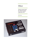
1
ABT/S
Aluminum Billet
Thermometer
User Guide
Issue E: February 2010
Part Nº is 198.184
Language: English
Copyright © 2003 - 2010 Land Instruments International
IMPORTANT INFORMATION - PLEASE READ
Important Health and Safety Information
Office Locations
Equipment Operation
Use of this instrument in a manner not specified by Land Instruments International may be hazardous.
Electrical Power Supply
Before working on the electrical connections all of the electrical power lines to the equipment must be isolated. All the
electrical cables and signal cables must be connected exactly as indicated in these operating instructions. If in doubt
contact Land Instruments International.
Face and Eye Protection
Suitable face and eye protection must be worn when working on hot vessels and ducts! Special safety measures must be
taken when working on a high-pressure duct.
Protective Clothing
Protective clothing must always be worn when working in the vicinity of hot vessels or ducts.
UK - Dronfield
Tel: +44 (0) 1246 417691
E-Mail: [email protected]
Web: www.landinst.com
USA - Pittsburgh
AMETEK Land, Inc.
Tel: +1 412 826 4444
E-Mail: [email protected]
Web: www.ametek-land.com
For further details on all LAND/
Ametek offices, distributors and
representatives, please visit our
websites.
Storage
The instrument should be stored in its packaging, in a dry sheltered area.
Unpacking
Check all packages for external signs of damage. Check the contents against the packing note.
Return of Damaged Goods
IMPORTANT
If any item has been damaged in transit, this should be reported to the carrier and to the supplier immediately. Damage
caused in transit is the responsibility of the carrier not the supplier.
DO NOT RETURN a damaged instrument to the sender as the carrier will not then consider a claim. Save the packing with
the damaged article for inspection by the carrier.
Return of Goods for Repair
If you need to return goods for repair please contact our Customer Service Department. They will be able to advise you on
the correct returns procedure.
Any item returned to Land Instruments International should be adequately packaged to prevent damage during transit.
You must include a written report of the problem together with your own name and contact information, address,
telephone number, email address etc.
Return of Goods for Repair Form is available for download from our websites.
Lifting Instructions
Where items are too heavy to be lifted manually, use suitably rated lifting equipment. Refer to the Technical Specification
for weights. All lifting should be done as stated in local regulations.
Design and Manufacturing Standards
The Quality Management System of
Land Instruments International is approved
to BS EN ISO 9001 for the design,
manufacture and on-site servicing of
combustion, environmental monitoring and
non-contact temperature measuring
instrumentation.
Signs and Symbols Used on
Equipment and Documentation
Caution, risk of electric shock.
Caution, attention to possibility of risk of damage to the product,
process or surroundings. Refer to instruction manual.
Caution, hot surface.
Approvals apply in the USA
This instrument complies with current European directives relating to
Electromagnetic Compatibility 89/336/EEC and Low Voltage Directive
73/23/EEC.
Operation of radio transmitters, telephones or other electrical/electronic devices in
close proximity to the equipment while the enclosure doors of the instrument or its
peripherals are open, may cause interference and possible failure where the radiated
emissions exceed the EMC directive.
The protection provided by both CE and IP classifications to this product may be
invalidated if alterations or additions are made to the structural, electrical, mechanical
or pneumatic parts of this system. Such changes may also invalidate the standard terms
of warranty.
Dimensions
Unless otherwise stated, all measurements are given in millimetres and inches.
Copyright
This manual is provided as an aid to owners of Land Instruments International’s products
and contains information proprietary to Land Instruments International. This manual may
not, in whole or part, be copied, or reproduced without the expressed written consent
of Land Instruments International Ltd.
Copyright © 2007 - 2010 Land Instruments International.
This item or material can be recycled.
This item or material must be disposed of in accordance
with the Waste Electrical and Electronic Equipment
directive as applied by local regulations.
Protective Conductor Terminal.
Observe precautions for handling electrostatic discharge
sensitive devices.
Thermometer
User Guide
ABT/S
User Guide
Thermometer
Contents
1
2
3
4
5
6
Introduction
1
1.1 About this Guide
1.2 About the ABT/S Thermometer System
1.2.1System Features
1.3 Unpacking the ABT/S
1.4 Nomenclature 1.5 Specifications
1
1
2
2
2
3
Introduction to the ABT/S
4
2.1 System Overview
2.2 Billet measurement problems and solutions
2.2.1 The effect of alloy type and surface finish
2.2.2Temperature gradients and speed of response
2.2.3Effect of heater type 2.2.4Effect of billet diameter
2.3 Choice of measurement location
4
4
5
6
6
6
8
Installing the ABT/S
9
3.1 Installing the Optic Head
3.2 Installing the Lightguide
3.3 Positioning the electronics unit
3.4 Electrical connections
3.4.1Electrical connections to Landmark processors
3.5 Installing the processor
3.6 Connecting other Land thermometers to the system
9
10
10
14
14
14
16
Maintenance
18
4.1 Optic head
4.1.1Replacement of the protection window
18
18
Operating the System
19
5.1 Configuring the processor
5.1.1Landmark Graphic Snap Shot Configuration 5.1.2Landmark Classic and Basic Configuration 5.2 Determining the optimum emessivity setting for a given billet
19
19
19
20
Accessories
21
6.1 ABT Purge Adapter
21
ABT/S
Thermometer
User Guide
User Guide
Thermometer
1 Introduction
1.1 About this Guide
This guide provides the information necessary to install and operate a Land
Aluminum Billet Thermometer (ABT/S).
1.2 About the ABT/S Thermometer System
The Land ABT/S system is an application dedicated product designed for
the measurement of aluminium billet temperatures. The system consists
of a highly accurate, non contact radiation thermometer coupled to a Land
Landmark Graphic AE signal processor.
ABT/S
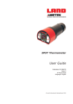
Fig. 1 Aluminum Billet Thermometer
AD990192
Page 1
Thermometer
User Guide
1.2.1 System Features
Unique Land emissivity enhancement technology provides high immunity to
variation of alloy type and surface finish.
Extremely fast response allows checking of billet temperature characteristics
during transfer from heater to press, without additional delay.
A fibre optics light guide, available in a range of lengths, allows the
thermometer electronics to be located remotely from heat and
induction fields.
1.3 Unpacking the ABT/S
The system comprises:
An ABT/S thermometer, consisting of optic head, light guide and thermometer electronics unit.
A Landmark Graphic AE (LMG AE) processor.
Documentation binder, containing:
ABT/S User Guide.
Landmark processor Installation Guide.
Landmark Graphic AE processor User Guide.
1.4 Nomenclature
The thermometer detail label is on the rear face of the thermometer.
Make a note of your thermometer Type and Serial Number in the space
provided below. This information is required to configure a Landmark
processor to work with your thermometer.
Instrument type:
ABT/S:
e.g:
L
S
ABT 300/600C L35 S
Serial Number:
Page 2
ABT/S
User Guide
Thermometer
1.5 Specifications
Temperature range:
300 to 600°C/600 to 1100°F
Response time:
5ms (0 to 95%)
Typical accuracy in
application:
±5°C/9°F
0.2°/°ambient
Stability (temperature):
Stability (time):
2°C/4°F per year
Vibration:
3G Any axis 10 to 300 Hz
Humidity:
0 to 99% non condensing
Sealing:
To IP54 requirements
Ambient temperature:
Optic head:
Light guide:
Electronics unit:
Specified:
Operating:
EMC:
ABT/S
165°C/330°F
200°C/392°F
0 to 50°C/32 to 122°F
-10 to 60°C/14 to 140°F
EN 50-082-2 (immunity),
EN 50-081-1 (emission),
IEC 1010 (safety)
Page 3
Thermometer
User Guide
2 Introduction to the ABT/S
The ABT/S is a fast, accurate, non contact radiation thermometry system,
which is intended to replace thermocouples for the measurement of
temperatures on the cylindrical surfaces of aluminium billets. Unlike other
infrared devices that have been used in this application, the ABT/S has
been developed specifically for measurements on these oxidised surfaces. It
is therefore highly tolerant of changes in both alloy type and surface finish.
Please note that the ABT/S is not recommended for measurements on ‘fresh’
aluminium surfaces such as the sawn end faces of the billet.
In the sections that follow, some of the issues involved in temperature
measurements on aluminium billets are examined. Please consider
this material carefully. It will help you to get the best performance from
your ABT/S
2.1 System Overview
The system has two main components, the ABT/S thermometer (Fig. 1) and a
Landmark processor.
The ABT/S thermometer consists of an optic head, a fibre optics light guide,
and an electronics unit. The optic head incorporates Land’s unique non contact
emissivity enhancement technology (patents applied for).
The recommended processor is the Snap Shot version of the Landmark
Graphic, with special features to support the ABT/S thermometer. The
processor retains its standard functions, such as averaging, peak-picking
and graphical display, and can support up to four thermometers in total.
Combinations of ABT/S and other Land thermometers are possible, subject to
certain restrictions.
2.2 Billet measurement problems and solutions
There are several factors that affect the infrared ‘signature’ of aluminium
billets. Alloy type, surface finish, and the use of gas and/or induction
heating, can all be influential. The presence, in many cases, of a longitudinal
temperature gradient, or ‘taper’, further complicates the measurement task.
Page 4
ABT/S
User Guide
Thermometer
2.2.1 The effect of alloy type and surface finish
The ABT/S uses Land’s emissivity enhancement technology to raise the
emissivity of the billet surface at the target location close to that of a black
body source. This means that, in general, it is not necessary to adjust the
system settings (ε = 0.95) to take account of either alloy type or billet
condition. Exceptions to this are:
•
1000 series alloys exhibit very bright surfaces and typically require an emissivity setting of around 0.85.
•
Billets produced by extrusion.
•
Billets where the outer surface has been machined away after casting.
In all of the above cases, apply the procedure for determining the optimum
setting for a given billet type, as described in Section 5.2.
Longitudinal heat flow
Radial heat flow
T
Radial temperature gradient
T
Longitudinal temperature gradient
Surface
Radial distance from axis
Distance along billet
Fig. 2 Typical billet heat transfer characteristics
ABT/S
AD990193
Page 5
Thermometer
User Guide
2.2.2 Temperature gradients and speed of response
It is important to recognise that the temperature distribution in a taper-heated
billet is constantly changing. The billet will lose heat to its surroundings but
this takes place fairly slowly.
Heat transfer within the billet is much more important in the short term,
particularly when a taper has been applied. Temperature gradients within the
billet will exist radially (surface to core), longitudinally, and rotationally (i.e. as
a function of azimuth angle).
From the time heating stops the imposed temperature gradients will begin to
decay (See Fig. 2). This internal heat transfer is relatively quick - longitudinal
gradients (principally the applied taper) will typically halve every few minutes.
The speed of the measuring device is therefore very important. When using
thermocouples for billet measurements, the taper may fall by as much as
5°C/9°F in the time the billet spends at the checking station.
The ABT/S has a much faster response than either thermocouples or the
various multi-wavelength infrared thermometers typically used at the die exit.
Typical accuracy of the ABT/S on 6000 series alloys is ±3°C/±6°F, which
is comparable to the change in taper which could be expected to take place
during a thermocouple measurement.
A single ABT/S unit can measure the taper of a passing billet, replacing a
complete bank of thermocouples, without delaying the loading of the billet into
the container.
The ABT/S processor temperature output is updated every 10ms. For typical
billet lengths (~500mm/20in) and transfer speeds (~0.5m/s/1.5ft/s), this
allows up to one hundred temperature data points to be recorded per billet.
2.2.3 Effect of heater type
The type of heater used has been found to have little effect upon the
performance of the ABT/S.
2.2.4 Effect of billet diameter
The ABT/S has been successfully tested on billet diameters from 175 to
225mm/7 to 9in. Larger diameters will not present problems but excessively
small billets may require adjustment of the system settings, as per
Section 5.2.
Page 6
ABT/S
ABT/S
Billet heater
Billet
ABT/S optic head
Optimum position
for ABT/S used for billet
heater checking
Holding position
Optimum position
for ABT/S used for
press control
Press
Loader
User Guide
Thermometer
Fig. 3 Typical Aluminium Billet heater and press arrangement
AD990194
Page 7
Thermometer
User Guide
2.3 Choice of measurement location
The ABT/S provides a superior alternative to banks of thermocouples in the
measurement of billet tapers, either immediately prior to extrusion or on exit
from the heater.
When measuring prior to extrusion, it is generally best to mount the optic
head in the last suitable location before the loader. This allows time for
the local surface and core temperatures to equalise but avoids additional
loss of taper.
In certain cases, a considerable period of time (i.e. one in which significant
cooling takes place) may elapse between a given billet exiting the heater and
being loaded into the container. This typically arises when the billet emerges
from the heater before the previous press cycle has been completed. In this
situation, the billet is usually moved to a ‘holding position’ where it waits
until the press is ready to accept it. If the ABT/S is being used as an aid to
press control, the preferred location for the optic head is between the ‘holding
position’ and the press. This gives a representative measure of the billet’s
temperature characteristics immediately before extrusion. Conversely, if billet
heater performance is to be measured then the optic head should be located
before the ‘holding position’.
Most presses offer suitable locations for one or both modes of operation. A
schematic diagram showing a typical press and heater layout is given in Fig. 3.
The optimum position for the ABT/S in each case is marked.
One final consideration in choosing a location is the precision with which the
billet is located. The optic head should be 15 to 20mm/0.6 to 0.8in from the
billet surface, at the point of closest approach, so reproducible positioning of
the billet is required (see Fig. 4).
Page 8
ABT/S
User Guide
Thermometer
3 Installing the ABT/S
NOTE
Read Section 2.0 of this User Guide before installing the thermometer.
3.1 Installing the optic head
Once a suitable location has been identified, the optic head must be positioned
as shown in Fig. 4. The window surface should be 15 to 20mm/ 0.6 to 0.8in
from, and parallel to, the billet surface at its point of closest approach.
The installation dimensions for the optic head are given in Figs. 5 and 6.
The recommended mounting method is via the two M6 tapped holes on the
rear of the unit. Alternatively, the optic head can be mounted via the four
6.5mm/0.25in holes in the front plate.
To prevent dirt collecting on the protection window, angle the unit downwards,
as shown in Fig. 4.
15 to 20mm
Optic head
Billet
Fig. 4 Recommended orientation of Optic Head with respect to billet
ABT/S
AD990195
Page 9
Thermometer
User Guide
3.2 Installing the lightguide
When installing the fibre optics light guide, observe the following precautions;
1)
Ensure that the light guide is not be subjected to any tension or other undue force. It is not necessary to secure the light guide to surrounding structures unless, by leaving it hanging, it will vibrate violently, be a nuisance or a hazard.
2)
Install the light guide as if it were a lightweight electrical cable and protect it if necessary. The minimum bend radius is 50mm/2in.
3.3 Positioning the electronics unit
When choosing a location for the electronics unit, observe the following
precautions;
1)
If the thermometer is to be installed in a location where the ambient
temperature is outside the range specified for the thermometer, it must be mounted in a special cooling/heating jacket available from Land Infrared.
2)
If the thermometer is to be used in conjunction with a protection jacket, refer to the Installation Guide provided with the jacket.
3)
If the thermometer is to be installed in a location where the ambient
temperature is within the range specified for the thermometer, it can be mounted using the two tapped holes on the mounting pad. Either hole can be used for direct tripod mounting.
4)
Choose a location for the thermometer which is free from excess vibration, dirt and moisture.
5)
It is recommended that, in order to minimise the build-up of dirt etc. on the electrical and light guide connectors, the thermometer is mounted such that these connectors are on the underside (as shown in Fig. 5).
Page 10
ABT/S
Thermometer
34.5/1.4
80/3.1
User Guide
25/1.0 55/2.2
156/6.1
115/4.5
Mounting pad 2 holes 1/4in BSW,
7/0.3 deep
on 25/1.0 centres
100/3.9
Recommended orientation
of thermometer to prevent
build up of dirt etc.
on electrical and
lightguide connectors
Minimum Bend
Radius 50.0/2.0
Lightguide Length
L10 = 1000/39.4
L20 = 2000/78.7
L35 = 3500/137.8
73/2.9
All dimensions in mm/in.
Fig. 5 Aluminium Billet Thermometer installation dimensions
ABT/S
AD990196
Page 11
Thermometer
User Guide
Recommended mounting
2 off M6 threaded holes
(Bolts supplied)
17/0.7
37/1. 5
73/2.9
100/3.9
17/0.7
100/3.9
84/3.3
84/3.3
Alternative mounting
4 off Ø6.5/0.25 holes
50/2.0
Fig. 6 Optic head installation dimensions
Page 12
AD00078
ABT/S
User Guide
Thermometer
Electrical connection socket
on rear of thermometer
Fig. 7 Location of 6-way electrical connection socket
Lugs
Keyway
AD990197
Marker
Marker
Fig. 8 Connection of pre-wired cable to the thermometer
Processor Pin No
1
2
3
4
5
6
7
Cable Colour
Yellow
Blue
White
Screen
Red
Black
Green
Fig. 9 Cable connection schedule
ABT/S
S4970229
Function
T+
TE+
Screen
V+
VES4970230
Page 13
Thermometer
User Guide
3.4 Electrical connections
Refer to the Processor Installation Guide for the connection schedule.
If the LMG AE processor is used (as recommended), extra input cards can be
added to allow the use of up to four thermometers in total (see section 3.6).
The electrical connections for the thermometer power supply, emissivity input
and temperature output are made via the 6-way socket on the rear of the
thermometer. See Fig. 7.
Electrical connection to the thermometer must be made via the pre-wired plug
(LAND Part Nº 029.673).
To connect the cable;
1)
Refer to Fig. 8. Align the red marker near the lugs of the pre-wired plug with the red marker above the keyway in the socket on the thermometer.
2)
Push the plug into the socket.
To disconnect the cable;
1)
Grip the ‘castellated’ section of the plug.
2)
Pull the plug outwards to release the locking mechanism and disconnect the cable.
3.4.1 Electrical connection to Landmark processors
The thermometer derives its power supply, emissivity input and temperature
output from the processor via the 6-way cable.
The cable connection schedule is given in Fig. 9.
3.5 Installing the processor
Refer to the relevant Landmark Processor Installation Guide.
Page 14
ABT/S
Thermometer
Extrusion
press
Billet
Furnace
ABT/S
Speed
Sensor
AET
Landmark Graphic AE Processor
Quenching
section
AQT
User Guide
Fig. 10 Aluminium extrusion temperature measurement system
(incorporating ABT/S)
ABT/S
AD990198
Page 15
Thermometer
User Guide
3.6 Connecting other Land thermometers to the system
The LMG AE processor can support up to four thermometers. These can be any
combination of Land ABT/S and System 4 thermometers.
This flexibility allows the ABT/S to form the basis of a complete extrusion
thermometry package as shown in Fig. 10. A single display presents
information from up to four infrared thermometers in a variety of formats.
Additional input cards can be fitted to an existing LMG AE processor. This
procedure can be undertaken on-site and takes only a few minutes.
Page 16
ABT/S
User Guide
Thermometer
Locating
pin
O ring
Hole
PTFE
washer
Locking
ring
Cable gland
Front
plate
Window
Body
Mounting
flat
Fig. 11 Optic head assembly details
ABT/S
AD990199
Page 17
Thermometer
User Guide
4 Maintenance
4.1 Optic head
After initial installation, make regular inspections of the optic head in order to
establish a cleaning cycle.
If the optic head requires cleaning, wipe both the window and the front plate
with a soft cloth. A little alcohol can be used to remove grease or oil
if necessary.
4.1.1 Replacement of the protection window
If it is necessary to replace the protection window refer to Fig. 11.
1)
Loosen the three grubscrews in the locking ring.
2)
Slacken the locking ring.
3)
Detach the front plate.
4)
Remove the old window and position its replacement in the recess in the front plate.
If necessary, use a small amount of silicone sealant to hold the window in place during reassembly.
Note that the optic head can be installed with the mounting flat in any one of four orientations. Each orientation is determined by aligning the pin on the front plate with the appropriate hole on the body of the
optic head.
5)
Select the orientation which best suits the particular installation. Tighten the locking ring onto the front plate.
Page 18
User Guide
Thermometer
5 Operating the System
5.1 Configuring the processor
Landmark processors offer a wide variety of features, such as time-functions
and, in the case of the Landmark Graphic AE, multi-channel and multilanguage support. Irrespective of the type of processor used it must be
configured for use with the ABT/S thermometer. Refer to the individual
processor user guides for further details.
An emissivity value of 0.95 will usually give good results on 6000 series alloys.
See also Sections 2.2.1 and 5.2.
5.1.1 Landmark Graphic Snap Shot Configuration
From the Thermometer Type list for the channel to which the Aluminium Billet
Thermometer is connected, choose ABT/S.
Settings for other Land aluminium extrusion products, including AET, should
also be present. If these thermometer types are not in the list then the
Landmark Graphic processor is not equipped to support the ABT/S; contact
Land for advice.
Set the required emissivity, as described in the Landmark Graphic AE
User Guide.
It is advisable, particularly in multichannel systems, to set a suitable channel
label, e.g. PRESS 1 or BILLET. Specific instructions are contained in the
Landmark Graphic Snap Shot User Guide.
5.1.2 Landmark Classic and Basic Configuration
The required span (either 300°C or 500°F) and minimum temperature
(either 300°C or 600°F) must be entered into the processor, by following the
procedures described in the individual processor User Guides.
Next, set the required emissivity, as described in the processor User Guide.
ABT/S
Page 19
Thermometer
User Guide
5.2 Determining the optimum emissivity setting for a given billet
An emissivity setting of 0.95 (factory setting) will give best performance on
6000 series alloys. A setting of 0.85 will improve accuracy on 1000 series
billets. To determine the optimum setting for a stationary billet of given type
(alloy and surface finish) proceed as follows:
1)
Position the optic head 15 to 20mm/0.6 to 0.8in from the billet, as
shown in Fig. 4. Ensure that the surface area under the optic head is
typical of that billet type; avoid heavily scratched or unusually black
areas.
2)
Take a reference thermocouple reading on the surface of the billet as
close as possible to the optic head. On taper-heated billets it is generally better to take the reading at one of the two positions shown in Fig. 12 to minimise the differential between the two temperatures.
Note that the temperature gradient along the billet can exceed 1°C per cm/4.5°F per inch, so accurate positioning is important.
3)
Adjust the processor emissivity until the ABT/S and the thermocouple
reading agree. For each degree Celsius that the ABT/S reads low with
respect to the thermocouple, it will be necessary to reduce the emissivity setting by around 0.02.
If an emissivity value greater than 1.00 is required, a poor thermocouple contact has been made.
4)
Check the validity of the emissivity setting on a few more billets by comparing the reference thermocouple reading to the ABT/S display.
In trials, optimum emissivity values between 0.88 and 0.98 have been obtained for billets of various commercial (6000 series) alloys. Slightly lower values (0.80 to 0.90) are expected on 1000 series alloys.
ABT/S optic head
Thermocouple measurement points
Fig. 12 Recommended position of reference thermocouple readings
Page 20
AD990200
ABT/S
User Guide
Thermometer
6 Accessories
6.1 ABT Purge Adapter
The ABT Purge Adaptor provides an effective air purge facility for the ABT/S
thermometer window. It is intended to extend the intervals between the
cleaning of the thermometer window, in those installations where rapid
contamination occurs. It does not however make the cleaning process
unnecessary.
For more detailed information regarding ABT Purge Adapter installation and
recommended air supply requirements, cross-refer to the ABT Purge Adapter
Installation User Supplement (ABTP198.232), supplied with the accessory.
ABT/S
Page 21
Thermometer
Page 22
User Guide
ABT/S
PRODUCT WARRANTY
Thank you for purchasing your new product from Land Instruments International. This Land
manufacturer’s ‘back-to-base’ warranty covers product malfunctions arising from defects in design
or manufacture. The warranty period commences on the instrument despatch date from the Land
Instruments International Ltd. factory in Dronfield, UK.
36 MONTHS WARRANTY
Building upon the reputation for reliability and longevity that System 4 and UNO thermometers
have earned, Land are delighted to be able to provide our customers with an industry-leading
36 month warranty for the following products:• System 4 thermometers, processors, accessories and mountings and special instruments
based on System 4.
• UNO thermometers, accessories and mountings and special instruments based on UNO.
• Application-dedicated processors based on LANDMARK® Graphic.
• ABTS/S and ABTS/U.
• FTS.
• VDT/S and VDT/U.
• DTT.
• FLT5/A.
This 36 month warranty is provided as standard for all orders for the products listed above received from
1st May 2002.
We believe that our customers expect us to set the standard in terms of performance, quality, reliability and
value for money. This 36 months warranty, as a part of an on-going program of continuous improvement,
is just one way in which Land strive to maintain our position as the temperature measurement partner of
choice.
12 MONTHS WARRANTY
All Land Instruments International products not provided with 36 months warranty (see list above), are
provided with a 12 months warranty.
PRODUCT WARRANTY
EXCLUSIONS FROM WARRANTY
It should be noted that costs associated with calibration checks which may be requested during the warranty
period are not covered within the warranty.
Land reserve the right to charge for service/calibration checks undertaken during the warranty period if the
cause is deemed to fall outside the terms of the warranty.
This Land manufacturer’s warranty does not cover product malfunction arising from:• incorrect electrical wiring.
• connection to electrical power sources outside the rating of the product.
• physical shock (being dropped, etc.) and impact damage.
• inappropriate routing, support, physical shock & strain protection, etc. of the lightguide (Fibroptic
thermometers only).
• environmental conditions exceeding the IP / NEMA rating of the product.
• environmental conditions outside the Ambient Temperature, Humidity and Vibration rating of the product.
• environmental contamination (solvent vapours, deposition of airborne contamination, cooling liquids of
non-neutral pH, etc.).
• overheating as a result of interruption of water/air flow through cooling jackets or of incorrect installation.
• inappropriate modification of product (drilling holes in thermometer bodies, etc.).
• inappropriate recalibration which results in product calibration being taken outside specification.
• improper resealing of thermometer following parameter adjustment (UNO, FLT5/A, etc.).
• attempted repair by a non-Land-authorised repair centre.
Land Instruments International Ltd • Dronfield S18 1DJ
Email: [email protected] • www.landinst.com
AMETEK Land, Inc.
•
150 Freeport Rd.
Email: [email protected] • www.ametek-land.com
•
•
England
Pittsburgh,
•
PA
Tel: +44 (0) 1246 417691 •
15238
•
U.S.A.
•
Fax: +44 (0) 1246 410585
Te l :
+1
(412)
826
4444
06/10
For a complete list of our international offices, please visit www.landinst.com