1
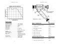
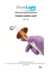
85300M Rev1 9/7/2007
85300M Rev1 9/7/2007
Limited Warranty:
FJW OPTICAL SYSTEMS INC. warrants the UV-Scope FIND-RSCOPE® (exclusive of batteries) to be free from defects in workmanship and material. This obligation shall be limited to the repair
and/or replacement (at FJW OPTICAL SYSTEMS, INC. option) of
articles or parts for which notice of defect is given in writing by the
purchaser to FJW OPTICAL SYSTEMS, INC. within ninety (90)
days from the date of shipment to the purchaser. Additionally,
FJW OPTICAL SYSTEMS, INC. warrants the Infrared Image Converter Tube and FIND-R-SCOPE® Power Supply and optics
(excluding Tube breakage) to be free from defects for a period of
18 months. This additional obligation is limited to the repair and/or
replacement (at the option of FJW OPTICAL SYSTEMS, INC.) of
these items. The notice of defect must be given in writing by the
purchaser to FJW OPTICAL SYSTEMS, INC. within 18 months
from the date of shipment to the customer. This warranty is in lieu
of all other warranties and expresses the sole liability of FJW OPTICAL SYSTEMS, INC. with respect to the product.
FIND-R-SCOPE
Ultraviolet Viewer
User’s Manual
For FJW Model Numbers
85300 and 85300-5
Other FIND-R-SCOPE® Product Lines:
FIND-R-SCOPE®
FIND-R-SCOPE®
FIND-R-SCOPE®
FIND-R-SCOPE®
FIND-R-SCOPE®
FIND-R-SCOPE®
FIND-R-SCOPE®
and
Infrared viewer with IR light source
1800 & 2200 camera/viewers
Infrared video system & monitor
Helmet & microscope units
UV viewers
Electronic infrared viewer
Radiometric infrared viewer/camera
The Speckle Buster®.
FJW Optical Systems, Inc.
322 N. Woodwork Lane
Palatine, Illinois 60067-4933
Tel: 847-358-2500
Fax: 847-358-2533
E-mail: [email protected]
Web: www.findrscope.com
F J W Optical Systems, Inc.
85300M Rev1 9/7/2007
Introduction
85300M Rev1 9/7/2007
UV-SCOPE PARTS and ACCESSORIES LIST
Thank you for purchasing the FJW Ultraviolet Viewer. Your new
UV-SCOPE is a wide angle, monocular, long-wave ultraviolet
viewer with a focal range from 114.3 mm (4.5 inches) to infinity.
It is fabricated utilizing a rugged polycarbonate body with aluminum housed precision ground optics, eyepiece, and objective
lenses. It consists of several modular components which are
listed on the following page. Preassembled, tested, and ready
for use, the FIND-R-SCOPE® UV-Scope ultraviolet viewer
should provide many years of trouble-free operation.
(call for current prices)
Part
Item
Description
IR & UV VIEWERS
85300
UV-SCOPE
180-1350 nm
Hand-held, self contained, monocular UV-nearinfrared viewer w/spectral sensitivity from 180 to
1350 nm, with 26 mm f/3.0 UV-grade fused silica
lens, and ≈ 1x magnification.
85300-5
UV-SCOPE
180-1550 nm
Hand-held, self contained, monocular UV-nearinfrared viewer with extended spectral sensitivity
from 180 to 1550 nm, with 26 mm f/3.0 UV-grade
fused silica lens, and ≈ 1x magnification.
Operating Procedures
VIEWER ACCESSORIES
Special Filters
Special order filters available, prices vary
80380
Neck Strap
Neck strap to screw into 85300 handle
80385
Wrist Strap
Wrist strap to screw into 85300 handle
80389
Close-up Lens
Attachment for viewing within 6” of target
80451
Variable Iris
Attachment to increase depth of field
Caution: Viewing excessively high powered light may damage the UV-SCOPE image tube.
81850
Volt Converter
120 Vac, 60Hz Adapter to operate from wall outlet
81850-1
Volt Converter
230 Vac, 50Hz Adapter to operate from wall outlet
1. Unscrew the End Cap Assembly and insert enclosed "C" cell
battery (+ side down into the end cap); re-assemble.
2. Remove the lens cap.
3. Turn the viewer switch ON.
4. Pre-focus the eyepiece lens by rotating the rubber portion to
clarify the phosphor screen "grain" of the image tube.
85206
16mm Lens
16mm C-mount camera lens
85255
8mm Lens
8mm C-mount camera lens
In order to view any object, it must emit, or be illuminated by,
some quantity of light, be it visible or ultraviolet. Incandescent
room lights and daylight are both acceptable for checking instrument operation.
Caution: Rotating the eyepiece beyond the point of easy
movement may damage the image tube.
5. Direct the viewer towards the illuminated object and look
through the eyepiece lens.
6. Focus the objective lens by rotating the lens to obtain the
clearest and sharpest image possible.
7. Repeat STEP 4 to fine-focus and maximize image clarity.
8. Be sure to turn viewer switch OFF when not in use.
1
REPLACEMENT PARTS
61883
Eyeshield
Rubber eyepiece eyeshield
61897
Power Supply
12,000V internal power supply
80000
Eyepiece Lens
Eyepiece lens
93330
UV Objective
Lens
UVATAR 3-element Objective Lens is the standard
lens supplied with models 85300 and 85300-5.
93380
UV Objective
Lens
UVAGON 5-element Objective Lens can be used in
lieu of the standard 3-element lens
85086
“C” cell Endcap C-Cell End Cap assembly for current models
85282
Carrying Case
Polypropylene case w/ die-cut interior
80064
Power Switch
On/Off switch
93001
180nm Tube
180nm to 1300 nm image converter tube
93001-5
180nm Tube
180nm to 1500 nm image converter tube
6
85300M Rev1 9/7/2007
85300M Rev1 9/7/2007
Specifications
Standard Sensitivity………………….
Optional Sensitivity …………………
Peak Sensitivity………………………
Field of View………………………….
Magnification…………………………
Focal Range………………………….
Dimensions…………………………..
…………………………..
Weight…………………………………
Tube Resolution……………………..
Power Supply Life……………………
Battery Life……………………………
……………………………
Body Material…………………………
Operating Temp………………………
……………………..
180 to 1350 nm
180 to 1550 nm
300 nm
40º
1:1
4” to infinity
6 x 2c x 7 in.
15.25 x 5.4 x 17.8 cm.
22 oz./ 625g
50 lines/mm (min)
2500 hours
250 hours (intermittent)
350 hours (continuous)
Polycarbonate
-25ºF to 115ºF
-32ºC to 46ºC
Major Components
Part Number
1.
Eyepiece Lens with Rubber Shield
80000
2.
ON/OFF Switch
Depends on serial #
3.
High Voltage Power Supply
61897
4.
“C” cell battery
80148
5.
Battery End Cap Assembly
85086
6.
Image Converter Tube
93001
6.
Image Converter Tube
93001-5
7.
Quartz UV Lens Assembly
93330
Optional Objective Lens
Part Number
7. One Element Quartz UV Objective
85310
7. 5 Element UV Achromat Objective
93380
5
2
85300M Rev1 9/7/2007
85300M Rev1 9/7/2007
Component Replacement
The UV-SCOPE is designed for ease of service. The following list contains specific details:
1. LENSES: The eyepiece and objective lenses are retained by threads on their tubular housings.
a) TO REMOVE THE LENSES - Grasp the instrument
in one hand such that the lens to be removed faces
up. With the other hand, rotate the lens counterclockwise two or three revolutions until free.
b) TO REPLACE THE LENSES - Engage screw
threads and rotate clockwise two or three revolutions until snug.
Do not force or over-tighten the lenses as damage to the tube may result. Care should be exercised in engaging and disengaging lenses in order
to protect the precision thread quality necessary for
proper visual alignment.
2. SPRINGS: The unit has coil springs located behind the
eyepiece assembly and in the battery end cap.
3. BATTERY: The unit has one “C” cell battery located in
the battery end cap.
a) TO REMOVE THE BATTERY: Grasp the instrument
securely and rotate the battery cap counterclockwise
until the cap comes off. Battery is free to be removed.
b) TO REPLACE THE BATTERY: Place the “C” cell
battery (+ side down) into the end cap. Place this
end cap assembly and battery into the handle. Rotate the assembly clockwise to engage the screw
threads. Do NOT force or over-tighten the endcap
3
4. POWER SUPPLY: A high voltage power supply is located
behind (above) the battery/end cap assembly.
Caution:
To avoid electrical shock, DO NOT REMOVE THE
POWER SUPPLY unless the power switch has been
turned off for at least five (5) minutes.
a) TO REMOVE THE POWER SUPPLY: Remove the
battery cap and battery per instruction 3a. Grasp
the viewer housing such that the opening faces
downward. Bump the open end against the palm of
the hand to dislodge the power supply.
b) TO REPLACE THE POWER SUPPLY: Insert the
smaller cylindrical diameter end first and press
firmly into place. Replace the battery and battery
end cap per instruction 3b.
5. IMAGE CONVERTER TUBE: The image tube is located
behind the eyepiece lens. Caution: This is a fragile
glass tube - Do Not Drop!
a) TO REMOVE THE IMAGE TUBE: Remove the
eyepiece lens per instruction la. Tilt housing downward keeping one hand under the opening. The
image tube should slide partially out. If not, tap the
housing lightly in your palm. Grasp the tube and
pull it free. A gentle tilting or rocking motion while
pulling away may be helpful.
b)
NOTE: For maximum performance, all external
surfaces of the image tube must be free of fingerprints and other dirt or high voltage arcing and image degradation may occur. Before replacing the
4