1
INTRODUCTION
−
HOW TO TROUBLESHOOT ECU CONTROLLED
SYSTEMS
IN−23
HOW TO PROCEED WITH TROUBLESHOOTING
IN08W−23
Carry out troubleshooting in accordance with the procedure on the following page. Here, only the basic procedure is shown. Details are provided in Diagnostics section, showing the most effective methods for each
circuit. Confirm the troubleshooting procedures first for the relevant circuit before beginning troubleshooting
of that circuit.
Vehicle Brought to Workshop
1
2
1
Ask the customer about the conditions and the
environment when the problem occurred.
Customer Problem
Analysis
Symptom Confirmation
and Diagnostic Trouble
Code Check
3
Symptom Simulation
2, 3
Confirm the symptoms and the problem conditions, and check the diagnostic trouble codes.
(When the problem symptoms do not appear during confirmation, use the symptom simulation
method described later on.)
4
Diagnostic Trouble
Code Chart
5
6
Problem Symptoms Table
Circuit Inspection or Parts
Inspection
7
Repair
8
Confirmation Test
End
LEXUS IS300/IS200 SUP (RM870E)
4, 5, 6
Check the results obtained in Step 2, then confirm
the inspection procedure for the system or the part
which should be checked using the diagnostic
trouble code chart or the problem symptoms table.
7
Check and repair the affected system or part in
accordance with the instructions in Step 6.
8
After completing repairs, confirm that the problem
has been eliminated.
(If the problem is not reproduced, perform the
confirmation test under the same conditions and
in the same environment as when it occurred for
the first time.)
IN−24
INTRODUCTION
−
HOW TO TROUBLESHOOT ECU CONTROLLED
SYSTEMS
1.
CUSTOMER PROBLEM ANALYSIS
In troubleshooting, the problem symptoms must be confirmed accurately and all preconceptions must be
cleared away in order to give an accurate judgement. To ascertain just what the problem symptoms are, it
is extremely important to ask the customer about the problem and the conditions at the time it occurred.
Important Point in the Problem Analysis:
The following 5 items are important points in the problem analysis. Past problems which are thought to be
unrelated and the repair history, etc. may also help in some cases, so as much information as possible should
be gathered and its relationship with the problem symptoms should be correctly ascertained for reference
in troubleshooting. A customer problem analysis table is provided in Diagnostics section for each system
for your use.
Important Points in the Customer Problem Analysis
D What −−−−− Vehicle model, system name
D When −−−−− Date, time, occurrence frequency
D Where −−−−− Road conditions
D Under what conditions? −−−−− Running conditions, driving conditions, weather conditions
D How did it happen? −−−−− Problem symptoms
(Sample) Supplemental restraint system check sheet.
CUSTOMER PROBLEM ANALYSIS CHECK
Inspector’s
Name
Supplemental Restraint System Check Sheet
Registration No.
Registration Year
Customer’s Name
/
/
Frame No.
Date Vehicle Brought In
/
km
miles
Odometer Reading
/
Date Problem First Occurred
Weather
Temperature
Vehicle Operation
LEXUS IS300/IS200 SUP (RM870E)
/
Fine
Cloudy
Rainy
Snowy
/
Other
Approx.
Starting
Driving
[
Idling
Constant speed
Other
Acceleration
Deceleration
]
INTRODUCTION
−
IN−25
HOW TO TROUBLESHOOT ECU CONTROLLED
SYSTEMS
2.
SYMPTOM CONFIRMATION AND DIAGNOSTIC TROUBLE CODE CHECK
The diagnostic system in the LEXUS IS300/IS200 fulfills various functions. The first function is the Diagnostic Trouble Code Check in which a malfunction in the signal circuits to the ECU is stored in code in the ECU
memory at the time of occurrence, to be output by the technician during troubleshooting. Another function
is the Input Signal Check which checks if the signals from various switches are sent to the ECU correctly.
By using these check functions, the problem areas can be narrowed down quickly and troubleshooting can
be performed effectively. Diagnostic functions are incorporated in the following systems in the LEXUS
IS300/IS200.
Diagnostic Trouble
Code Check
Input Signal Check
(Sensor Check)
Diagnostic Test
Mode (Active Test)
1. Engine (2JZ−GE)
f
(with Check Mode)
f
f
2. Automatic Transmission (A650E)
f
(with Check Mode)
f
f
3. ABS with EBD & BA & TRC System
f
f
f
4. ABS with EBD & BA & TRC & VSC System
f
f
f
5. Supplemental Restraint System
f
System
6. Theft Deterrent System
f
7. Cruise Control System
f
8. Engine Immobiliser System
f
9. Body Control System
10.Multiplex Communication System
f
f
11.LEXUS Navigation System
12.Air Conditioning System
LEXUS IS300/IS200 SUP (RM870E)
f
f
f
f
f
IN−26
INTRODUCTION
−
HOW TO TROUBLESHOOT ECU CONTROLLED
SYSTEMS
In diagnostic trouble code check, it is very important to determine whether the problem indicated by the diagnostic trouble code is still occurring or occurred in the past but returned to normal at present. In addition,
it must be checked in the problem symptom check whether the malfunction indicated by the diagnostic
trouble code is directly related to the problem symptom or not. For this reason, the diagnostic trouble codes
should be checked before and after the symptom confirmation to determine the current conditions, as shown
in the table below. If this is not done, it may, depending on the case, result in unnecessary troubleshooting
for normally operating systems, thus making it more difficult to locate the problem, or in repairs not pertinent
to the problem. Therefore, always follow the procedure in correct order and perform the diagnostic trouble
code check.
DIAGNOSTIC TROUBLE CODE CHECK PROCEDURE
Diagnostic Trouble
Code Check (Make a
note of and then clear)
Diagnostic Trouble
Code Display
Confirmation
of Symptoms
Diagnostic Trouble
Code Check
Problem symptoms Same diagnostic
trouble code is
exist
displayed
Normal code is
displayed
Normal Code Display
Problem Condition
Problem is still occurring in the diagnostic
circuit
The problem is still occurring in a place
other than in the diagnostic circuit
(The diagnostic trouble code displayed
first is either for a past problem or it is a
secondary problem)
No problem
symptoms exist
The problem occurred in the diagnostic
circuit in the past
Problem symptoms Normal code is
exist
displayed
The problem is still occurring in a place
other than in the diagnostic circuit
No problem
symptoms exist
The problem occurred in a place other
than in the diagnostic circuit in the past
LEXUS IS300/IS200 SUP (RM870E)
Normal code is
displayed
INTRODUCTION
−
HOW TO TROUBLESHOOT ECU CONTROLLED
SYSTEMS
IN−27
Taking into account the points on the previous page, a flow chart showing how to proceed with troubleshooting using the diagnostic trouble code check is shown below. This flow chart shows how to utilize the diagnostic trouble code check effectively, then by carefully checking the results, indicates how to proceed either to
diagnostic trouble code troubleshooting or to troubleshooting of problem symptoms table.
Diagnostic trouble code check
Making a note of and clearing of the diagnostic trouble codes displayed
Symptom confirmation
Problem symptoms
exist
No problem symptoms
exist
Simulation test using the symptom
simulation methods
Diagnostic trouble code check
D Diagnostic trouble code displayed
D Problem symptoms exist
Troubleshooting of problem indicated
by diagnostic trouble code
LEXUS IS300/IS200 SUP (RM870E)
D Normal code displayed
D Problem symptoms exist
Troubleshooting of each
problem symptom
D Normal code displayed
D No problem symptoms exist
System Normal
If a diagnostic trouble code was
displayed in the initial diagnostic
trouble code check, it indicates
that the trouble may have occurred
in a wire harness or connector in
that circuit in the past. Therefore,
check the wire harness and connectors (See page IN−34).
IN−28
INTRODUCTION
−
HOW TO TROUBLESHOOT ECU CONTROLLED
SYSTEMS
3.
SYMPTOM SIMULATION
The most difficult case in troubleshooting is when there are no problem symptoms occurring. In such cases,
a thorough customer problem analysis must be carried out, then simulate the same or similar conditions and
environment in which the problem occurred in the customer’s vehicle. No matter how much experience a
technician has, or how skilled he or she may be, if he or she proceeds to troubleshoot without confirming
the problem symptoms he or she will tend to overlook something important in the repair operation and make
a wrong guess somewhere, which will only lead to a standstill. For example, for a problem which only occurs
when the engine is cold, or for a problem which occurs due to vibration caused by the road during driving,
etc., the problem can never be determined so long as the symptoms are confirmed with the engine hot condition or the vehicle at a standstill. Since vibration, heat or water penetration (moisture) is likely to cause problem which is difficult to reproduce, the symptom simulation tests introduced here are effective measures in
that the external causes are applied to the vehicle in a stopped condition.
Important Points in the Symptom Simulation Test:
In the symptom simulation test, the problem symptoms should of course be confirmed, but the problem area
or parts must also be found out. To do this, narrow down the possible problem circuits according to the symptoms before starting this test and connect a tester beforehand. After that, carry out the symptom simulation
test, judging whether the circuit being tested is defective or normal and also confirming the problem symptoms at the same time. Refer to the problem symptoms table for each system to narrow down the possible
causes of the symptom.
1
VIBRATION METHOD: When vibration seems to be the major cause.
CONNECTORS
Slightly shake the connector vertically and horizontally.
Shake Slightly
WIRE HARNESS
Slightly shake the wire harness vertically and horizontally.
The connector joint, fulcrum of the vibration, and body
through portion are the major areas to be checked thoroughly.
Swing Slightly
PARTS AND SENSOR
Vibrate Slightly
Apply slight vibration with a finger to the part of the sensor
considered to be the problem cause and check that the malfunction occurs.
HINT:
Applying strong vibration to relays may result in open relays.
V07268
LEXUS IS300/IS200 SUP (RM870E)
INTRODUCTION
2
−
HOW TO TROUBLESHOOT ECU CONTROLLED
SYSTEMS
HEAT METHOD: When the problem seems to occur when the suspect area is heated.
Heat the component that is the likely cause of the malfunction
with a hair dryer or similar object. Check to see if the malfunction
occurs.
M a l f u n ction
NOTICE:
(1) Do not heat to more than 60˚C (140˚F). (Temperature
is limited not to damage the components.)
(2) Do not apply heat directly to parts in the ECU.
3
IN−29
WATER SPRINKLING METHOD: When the malfunction seems to occur on a rainy day or in a
high−humidity condition.
Sprinkle water onto the vehicle and check to see if the malfunction occurs.
NOTICE:
(1) Never sprinkle water directly into the engine compartment, but indirectly change the temperature and humidity by applying water spray onto the radiator front
surface.
(2) Never apply water directly onto the electronic components.
HINT:
If a vehicle is subject to water leakage, the leaked water may
contaminate the ECU. When testing a vehicle with a water leakage problem, special caution must be taken.
4
OTHER: When a malfunction seems to occur when electrical load is excessive.
Turn on all electrical loads including the heater blower, head
lights, rear window defogger, etc. and check to see if the malfunction occurs.
ON
B02389
B02390
LEXUS IS300/IS200 SUP (RM870E)
IN−30
INTRODUCTION
−
HOW TO TROUBLESHOOT ECU CONTROLLED
SYSTEMS
4.
DIAGNOSTIC TROUBLE CODE CHART
The inspection procedure is shown in the table below. This table permits efficient and accurate troubleshooting using the diagnostic trouble codes displayed in the diagnostic trouble code check. Proceed with troubleshooting in accordance with the inspection procedure given in the diagnostic chart corresponding to the
diagnostic trouble codes displayed. The Supplemental Restraint System diagnostic trouble code chart is
shown below as an example.
D DTC No.
Indicates the diagnostic trouble code.
D Page or Instructions
Indicates the page where the inspection procedure for each circuit is to be found, or gives
instructions for checking and repairs.
D Trouble Area
Indicates the suspect area of
the problem.
D Detection Item
Indicates the system of the problem or
contents of the problem.
DIAGNOSTIC TROUBLE CODE CHART
If a malfunction code is displayed during the DTC check, check the circuit for that code listed in the table
below (Proceed to the page given for that circuit).
DTC No.
(See page)
Detection Item
D Short in D squib circuit
B0100/13
(DI−119)
D Open in D squib circuit
B0101/14
(DI−124)
D Short in D squib circuit (to ground)
B0102/11
(DI−128)
D Short in D squib circuit (to B+)
B0103/12
(DI−132)
B0105/53
(DI−136)
D Short in P squib circuit
B0106/54
D Open in P squib circuit
Trouble Area
D Steering wheel pad (squib)
D Spiral cable
D Airbag sensor assembly
D Wire harness
ON
D Steering wheel pad (squib)
D Spiral cable
D Airbag sensor assembly
D Wire harness
ON
D Steering wheel pad (squib)
D Spiral cable
D Airbag sensor assembly
D Wire harness
ON
D Steering wheel pad (squib)
D Spiral cable
D Airbag sensor assembly
D Wire harness
ON
D Front Passenger airbag assembly (squib)
D Airbag sensor assembly
D Wire harness
D Front Passenger airbag assembly (squib)
D Airbag sensor assembly
D Wire harness
D Short in P squib circuit (to Ground)
LEXUS IS300/IS200 SUP (RM870E)
SRS
Warming Light
D Front Passenger airbag assembly (squib)
D Airbag sensor assembly
D Wire harness
ON
ON
ON
INTRODUCTION
−
IN−31
HOW TO TROUBLESHOOT ECU CONTROLLED
SYSTEMS
5.
PROBLEM SYMPTOMS TABLE
The suspected circuits or parts for each problem symptom are shown in the table below. Use this table to
troubleshoot the problem when a ”Normal” code is displayed in the diagnostic trouble code check but the
problem is still occurring. Numbers in the table indicate the inspection order in which the circuits or parts
should be checked.
HINT:
When the problem is not detected by the diagnostic system even though the problem symptom is present,
it is considered that the problem is occurring outside the detection range of the diagnostic system, or that
the problem is occurring in a system other than the diagnostic system.
D Page
Indicates the page where the flow chart for each circuit
is located.
D Circuit Inspection, Inspection Order
Indicates the circuit which needs to be checked for each problem
symptom. Check in the order indicated by the numbers.
Problem Symptom
D Circuit or Part Name
Indicates the circuit or part which needs to be checked.
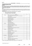
PROBLEM SYMPTOMS TABLE
Proceed with troubleshooting of each circuit in the table below.
Symptom
Suspected Area
See page
D With the ignition switch in the ACC or ON position, the SRS warning D SRS warning light circuit
light sometimes lights up after approx. 6 seconds have elapsed.
D SRS warning light is always lit up even when ignition switch is in
the LOCK position
D With the ignition switch in the ACC or ON position, the SRS warning light does not light up.
D DTC is not displayed.
D SRS warning light is always lit up at the time of DTC check procedure.
D DTC is displayed without Tc and CG terminal connection.
LEXUS IS300/IS200 SUP (RM870E)
(Always lights up when ignition switch is in LOCK
position.)
DI−180
D SRS warning light circuit
(Dose not light up when ignition switch is turned to
ACC or ON.)
D Tc terminal circuit
DI−183
DI−187
IN−32
INTRODUCTION
−
HOW TO TROUBLESHOOT ECU CONTROLLED
SYSTEMS
6.
CIRCUIT INSPECTION
How to read and use each page is shown below.
D Diagnostic Trouble Code No. and Detection Item
D Circuit Description
The major role and operation, etc. of the circuit
and its component parts are explained.
DTC
Short in D Squib Circuit
B0100/13
CIRCUIT DESCRIPTION
The D squib circuit consists of the airbag sensor assembly, spiral cable and steering wheel pad.
It causes the airbag to deploy when the airbag deployment conditions are satisfied.
For details of the function of each components,see OPERATION on page RS−2.
DTC B0100/13 is recorded when a short is detected in the D squib circuit.
DTC Detection Condition
DTC No.
Trouble Area
SShort circuit between D+ wire harness and D− wire harness of squib SSteering wheel pad (D squib)
B010013
SD squib malfunction
SSpiral cable
SSpiral cable malfunction
SAirbag sensor assembly
SAirbag sensor assembly malfunction
SWire harness
D Indicates the diagnostic trouble code, diagnostic
trouble code set parameter and suspect area of
the problem.
WIRING DIAGRAM
Airbag Sensor
Assembly
D squib
1 G−R
7
2 G−Y
6
Spiral
Cable
A15
D+
A15
D−
R16015
D Wiring Diagram
This shows a wiring diagram of the circuit.
Use this diagram together with ELECTRICAL WIRING DIAGRAM to thoroughly understand the circuit.
Wire colors are indicated by an alphabetical code.
B = Black, L = Blue, R = Red, BR = Brown,
LG = Light Green, V = Violet, G = Green,
O = Orange, W = White, GR = Gray, P = Pink,
Y = Yellow, SB = Sky Blue
The first letter indicates the basic wire color and the
second letter indicates the color of the stripe.
B00803
LEXUS IS300/IS200 SUP (RM870E)
INTRODUCTION
−
HOW TO TROUBLESHOOT ECU CONTROLLED
SYSTEMS
D Indicates the position of the ignition switch during the check.
D Inspection Procedure
Use the inspection procedure to determine
if the circuit is normal or abnormal, and if it
is abnormal, use it to determine whether the
problem is located in the sensors, actuators,
wire harness or ECU.
ON
LOCK
Ignition Switch ON
Ignition Switch LOCK (OFF)
START
ACC
Ignition Switch ACC
Ignition Switch START
IN−33
INSPECTION PROCEDURE
2
Check voltage at IG2 and ACC of airbag sensor assembly.
ON
Airbag Sensor Assembly
ACC
(−)
IG2
(+)
AB0119
W02766
H00041
PREPARATION:
Turn ignition switch ON.
CHECK:
Measure voltage between terminals IG2 and ACC of
airbag sensor assembly and body ground.
OK:
Voltage: Below 16 V
NG
OK
Check battery and charging system
(See charging system section).
D Indicates the place to check the voltage or resistance.
D Indicates the connector position to be checked, from the front or back side.
Wire Harness
Check from the connector back side
(with harness).
Check from the connector front side (without harness).
In this case, care must be taken not to bend the terminals.
D Indicates the condition of the connector of ECU during the check.
KNK
E6 Connector
Connector being checked is connected.
B00691
LEXUS IS300/IS200 SUP (RM870E)
KNK
E6 Connector
Connector being checked is disconnected.
B00972