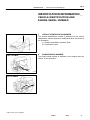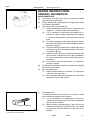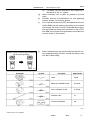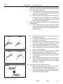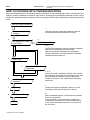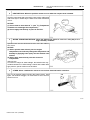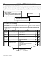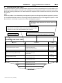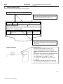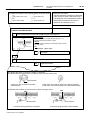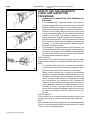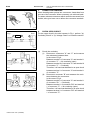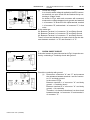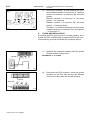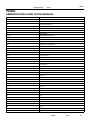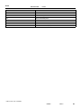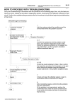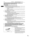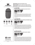
1
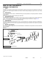
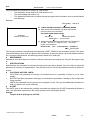
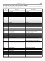
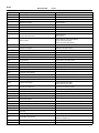
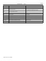
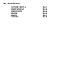
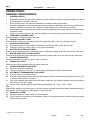
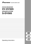
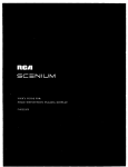
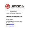
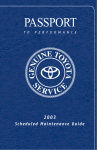
1996 TOYOTA T100
Factory Service Manual
INDEX
IN
MA
PP
SS
DI
EM
EC
MF
SF
CO
LU
IG
ST
CH
CL
MT
AT
TR
PR
SA
BR
SR
RS
BE
BO
AC
Introduction
Maintenance
Preparation
Service Specifications
Diagnostics
Engine Mechanical (3RZ-FE)
Engine Mechanical (5VZ-FE)
Emissions Control (3RZ-FE)
Emissions Control (5VZ-FE)
MFI System (3RZ-FE)
SFI System (5VZ-FE)
Cooling (3RZ-FE)
Cooling (5VZ-FE)
Lubrication (3RZ-FE)
Lubrication (5VZ-FE)
Ignition (3RZ-FE)
Ignition (5VZ-FE)
Starting (3RZ-FE)
Starting (5VZ-FE)
Charging (3RZ-FE)
Charging (5VZ-FE)
Clutch
Manual Transmission (R150, R150F)
Manual Transmission (W59)
Automatic Transmission
Transfer
Propeller Shaft
Suspension and Axle
Brake
Steering
Supplemental Restraint System
Body Electrical
Body
Air Conditioning
IN – INTRODUCTION
HOW TO USE THIS MANUAL
IDENTIFICATION INFORMATION
REPAIR INSTRUCTIONS
FOR ALL OF VEHICLES
HOW TO TROUBLESHOOT ECU
CONTROLLED SYSTEMS
TERMS
IN-1
IN-3
IN-4
IN-9
IN-15
IN-31
IN−1
INTRODUCTION
−
HOW TO USE THIS MANUAL
HOW TO USE THIS MANUAL
IN02D−02
GENERAL INFORMATION
1.
INDEX
An INDEX is provided on the first page of each section to guide you to the item to be repaired. To assist you
in finding your way through the manual, the Section Title and major heading are given at the top of every
page.
2.
PRECAUTION
At the beginning of each section, a PRECAUTION is given that pertains to all repair operations contained
in that section.
Read these precautions before starting any repair task.
3.
TROUBLESHOOTING
TROUBLESHOOTING tables are included for each system to help you diagnose the problem and find the
cause. The fundamentals of how to proceed with troubleshooting are described on page IN−16.
Be sure to read this before performing troubleshooting.
4.
PREPARATION
Preparation lists the SST (Special Service Tools), recommended tools, equipment, lubricant and SSM (Special Service Materials) which should be prepared before beginning the operation and explains the purpose
of each one.
5.
REPAIR PROCEDURES
Most repair operations begin with an overview illustration. It identifies the components and shows how the
parts fit together.
Example:
Filler Cap
Float
Clevis Pin
z Gasket
Reservoir Tank
Boot
z Grommet
Slotted Spring Pin
Clip
12 ( 120, 9)
Clevis
15 ( 155, 11)
Snap Ring
Washer
Piston
Lock Nut
Push Rod
Cylinder
N·m (kgf·cm, ft·lbf) : Specified torque
z Non−reusable part
N17080
1996 TOYOTA T100 (RM449U)
Author:
Date:
1
IN−2
INTRODUCTION
−
HOW TO USE THIS MANUAL
The procedures are presented in a step−by−step format:
S
The illustration shows what to do and where to do it.
S
The task heading tells what to do.
S
The detailed text tells how to perform the task and gives other information such as specifications
and warnings.
Example:
Task heading : what to do
21. CHECK PISTON STROKE OF OVERDRIVE BRAKE
(a) Place SST and a dial indicator onto the overdrive brake
piston as shown in the illustration.
SST 09350−30020 (09350−06120)
Illustration:
what to do and where
Set part No.
Detailed text :
Component part No.
how to do task
(b) Measure the stroke applying and releasing the compressed
air (392 − 785 kPa, 4 − 8 kgf.cm2 or 57 − 114 psi) as
shown in the illustration.
Piston stroke: 1.40 1.70 mm (0.0551 0.0669 in.)
Specification
This format provides the experienced technician with a FAST TRACK to the information needed. The upper
case task heading can be read at a glance when necessary, and the text below it provides detailed information. Important specifications and warnings always stand out in bold type.
6.
REFERENCES
References have been kept to a minimum. However, when they are required you are given the page to refer
to.
7.
SPECIFICATIONS
Specifications are presented in bold type throughout the text where needed. You never have to leave the
procedure to look up your specifications. They are also found in Service Specifications section for quick reference.
8.
CAUTIONS, NOTICES, HINTS:
S
CAUTIONS are presented in bold type, and indicate there is a possibility of injury to you or other
people.
S
NOTICES are also presented in bold type, and indicate the possibility of damage to the components
being repaired.
S
HINTS are separated from the text but do not appear in bold. They provide additional information to
help you perform the repair efficiently.
9.
SI UNIT
The UNITS given in this manual are primarily expressed according to the SI UNIT (International System of
Unit), and alternately expressed in the metric system and in the English System.
Example:
Torque: 30 N·m (310 kgf·cm, 22 ft·lbf)
1996 TOYOTA T100 (RM449U)
Author:
Date:
2
IN−3
INTRODUCTION
−
IDENTIFICATION INFORMATION
IDENTIFICATION INFORMATION
VEHICLE IDENTIFICATION AND
ENGINE SERIAL NUMBER
IN02E−02
1.
VEHICLE IDENTIFICATION NUMBER
The vehicle identification number is stamped on the vehicle
identification number plate and certification label, as shown in
the illustration.
A: Vehicle Identification Number Plate
B: Certification Label
A
2.
ENGINE SERIAL NUMBER
The engine serial number is stamped on the engine block as
shown, in the illustration.
B13830
1996 TOYOTA T100 (RM449U)
Author:
Date:
3
IN−4
INTRODUCTION
−
REPAIR INSTRUCTIONS
REPAIR INSTRUCTIONS
GENERAL INFORMATION
FI1066
BASIC REPAIR HINT
(a) Use fender, seat and floor covers to keep the vehicle
clean and prevent damage.
(b) During disassembly, keep parts in the appropriate order
to facilitate reassembly.
(c) Observe the following operations:
(1) Before performing electrical work, disconnect the
negative (−) terminal cable from the battery.
(2) If it is necessary to disconnect the battery for inspection or repair, always disconnect the negative
(−) terminal cable which is grounded to the vehicle
body.
(3) To prevent damage to the battery terminal, loosen
the cable nut and raise the cable straight up without
twisting or prying it.
(4) Clean the battery terminals and cable ends with a
clean shop rag. Do not scrape them with a file or other abrasive objects.
(5) Install the cable ends to the battery terminals with
the nut loose, and tighten the nut after installation.
Do not use a hammer to tap the cable ends onto the
terminals.
(6) Be sure the cover for the positive (+) terminal is
properly in place.
(d) Check hose and wiring connectors to make sure that they
are secure and correct.
(e) Non−reusable parts
(1) Always replace cotter pins, gaskets, O−rings and oil
seals etc. with new ones.
(2) Non−reusable parts are indicated in the component
illustrations by the ”z” symbol.
(f)
Seal Lock Adhesive
Z11554
IN0IL−01
Precoated parts
Precoated parts are bolts and nuts, etc. that are coated
with a seal lock adhesive at the factory.
(1) If a precoated part is retightened, loosened or
caused to move in any way, it must be recoated with
the specified adhesive.
(2) When reusing precoated parts, clean off the old
adhesive and dry with compressed air. Then apply
the specified seal lock adhesive to the bolt, nut or
threads.
1996 TOYOTA T100 (RM449U)
Author:
Date:
4
IN−5
INTRODUCTION
−
REPAIR INSTRUCTIONS
(3)
(g)
(h)
(i)
Medium Current Fuse and High Current Fuse
Equal Amperage Rating
(j)
Precoated parts are indicated in the component illustrations by the ”L” symbol.
When necessary, use a sealer on gaskets to prevent
leaks.
Carefully observe all specifications for bolt tightening
torques. Always use a torque wrench.
Use of special service tools (SST) and special service materials (SSM) may be required, depending on the nature
of the repair. Be sure to use SST and SSM where specified and follow the proper work procedure. A list of SST
and SSM can be found in the preparation part at the front
of each section in this manual.
When replacing fuses, be sure the new fuse has the correct amperage rating. DO NOT exceed the rating or use
one with a lower rating.
BE1367
Illustration
Symbol
Part Name
Abbreviation
FUSE
FUSE
MEDIUM CURRENT FUSE
M−FUSE
HIGH CURRENT FUSE
H−FUSE
FUSIBLE LINK
FL
CIRCUIT BREAKER
CB
V00076
1996 TOYOTA T100 (RM449U)
Author:
Date:
5
IN−6
INTRODUCTION
(k)
(l)
WRONG
(3)
(4)
(5)
IN0253
WRONG
(6)
CORRECT
(7)
(8)
IN0252
(m)
Example
REPAIR INSTRUCTIONS
Care must be taken when jacking up and supporting the
vehicle. Be sure to lift and support the vehicle at the proper locations (See page IN−8).
(1) If the vehicle is to be jacked up only at the front or
rear end, be sure to block the wheels at the opposite
end in order to ensure safety.
(2) After the vehicle is jacked up, be sure to support it
on stands. It is extremely dangerous to do any work
on a vehicle raised on a jack alone, even for a small
job that can be finished quickly.
Observe the following precautions to avoid damage to the
following parts:
(1) Do not open the cover or case of the ECU, ECM,
PCM or TCM unless absolutely necessary. (If the IC
terminals are touched, the IC may be destroyed by
static electricity.)
(2)
CORRECT
−
To disconnect vacuum hoses, pull off the end, not
the middle of the hose.
To pull apart electrical connectors, pull on the connector itself, not the wires.
Be careful not to drop electrical components, such
as sensors or relays. If they are dropped on a hard
floor, they should be replaced and not reused.
When steam cleaning an engine, protect the electronic components, air filter and emission−related
components from water.
Never use an impact wrench to remove or install
temperature switches or temperature sensors.
When checking continuity at the wire connector, insert the tester probe carefully to prevent terminals
from bending.
When using a vacuum gauge, never force the hose
onto a connector that is too large. Use a step−down
adapter for adjustment. Once the hose has been
stretched, it may leak.
Tag hoses before disconnecting them:
(1) When disconnecting vacuum hoses, use tags to
identify how they should be reconnected to.
(2) After completing a job, double check that the vacuum hoses are properly connected. A label under the
hood shows the proper layout.
IN0002
1996 TOYOTA T100 (RM449U)
Author:
Date:
6
IN−7
INTRODUCTION
(n)
−
REPAIR INSTRUCTIONS
Unless otherwise stated, all resistance is measured at an
ambient temperature of 20°C (68°F). Because the resistance may be outside specifications if measured at high
temperatures immediately after the vehicle has been running, measurement should be made when the engine has
cooled down.
1996 TOYOTA T100 (RM449U)
Author:
Date:
7
IN−8
INTRODUCTION
−
REPAIR INSTRUCTIONS
VEHICLE LIFT AND SUPPORT LOCATIONS
IN02G−02
[2WD]
[4WD]
JACK POSITION . . . . . . . . . . . . . . . . . . . . . . . . . . . . . . . . . . . . . . .
Front . . . . . . . . . . . . . . . Center of crossmember
Rear . . . . . . . . . . . . . . . Under the rear differential
SUPPORT POSITION
Safety stand . . . . . . . . . . . . . . . . . . . . . . . . . . . . . . . . . . . . . .
B01123
1996 TOYOTA T100 (RM449U)
IN−9
INTRODUCTION
−
FOR ALL OF VEHICLES
FOR ALL OF VEHICLES
PRECAUTION
Negative Cable
BO4111
IN02H−03
1.
(a)
FOR VEHICLES EQUIPPED WITH SRS AIRBAG
The TOYOTA T100 is equipped with an SRS (Supplemental Restraint System), such as the driver airbag.
Failure to carry out service operations in the correct sequence could cause the supplemental restraint system to
unexpectedly deploy during servicing, possibly leading to
a serious accident.
Further, if a mistake is made in servicing the supplemental
restraint system, it is possible the SRS may fail to operate
when required. Before servicing (including removal or
installation of parts, inspection or replacement), be sure
to read the following items carefully, then follow the correct procedure described in this manual.
(b)
GENERAL NOTICE
(1) Malfunction symptoms of the supplemental restraint system are difficult to confirm, so the diagnostic trouble codes become the most important
source of information when troubleshooting. When
troubleshooting the supplemental restraint system,
always inspect the diagnostic trouble codes before
disconnecting the battery (See page DI−365).
(2) Work must be started after 90 seconds from the
time the ignition switch is turned to the ”LOCK” position and the negative (−) terminal cable is disconnected from the battery.
(The supplemental restraint system is equipped
with a back−up power source so that if work is
started within 90 seconds of disconnecting the negative (−) terminal cable from the battery, the SRS
may deploy.)
When the negative (−) terminal cable is disconnected from the battery, memory of the clock and
audio systems will be cancelled. So before starting
work, make a record of the contents memorized by
the each memory system. Then when work is finished, reset the clock and audio systems as before.
To avoid erasing the memory of each memory system, never use a back−up power supply from outside the vehicle.
(3) Even in cases of a minor collision where the SRS
does not deploy, the steering wheel pad should be
inspected (See page RS−9).
1996 TOYOTA T100 (RM449U)
Author:
Date:
9
IN−10
INTRODUCTION
−
FOR ALL OF VEHICLES
(4)
Never use SRS parts from another vehicle. When
replacing parts, replace them with new parts.
(5) Before repairs, remove the center airbag sensor if
shocks are likely to be applied to the sensor during
repairs.
(6) Never disassemble and repair the center airbag
sensor assembly, steering wheel pad in order to reuse it.
(7) If the center airbag sensor assembly, steering
wheel pad have been dropped, or if there are
cracks, dents or other defects in the case, bracket
or connector, replace them with new ones.
(8) Do not expose the center airbag sensor assembly,
steering wheel pad directly to hot air or flames.
(9) Use a volt/ohmmeter with high impedance (10 kΩ/V
minimum) for troubleshooting of the electrical circuit.
(10) Information labels are attached to the periphery of
the SRS components. Follow the instructions on the
notices.
(11) After work on the supplemental restraint system is
completed, check the SRS warning light (See page
DI−365).
(c)
Front
B01124
FRONT AIRBAG SENSOR
(1) Never reuse the front airbag sensors involved in a
collision that activated the supplemental restraint
system. (Replace both left and right airbag sensors.)
(2) Install the front airbag sensor with the arrow on the
sensor facing toward the front of the vehicle.
The front airbag sensor set bolts have been anti−
rust treated. When the sensor is removed, always
replace the set bolts with new ones.
(3) The front airbag sensor is equipped with an electrical connection check mechanism. Be sure to lock
this mechanism securely when connecting the connector.
(4) If connector is not securely locked, a malfunction
code will be the diagnosis system (See page
RS−2).
1996 TOYOTA T100 (RM449U)
Author:
Date:
10
IN−11
INTRODUCTION
(d)
Red Mark
−
FOR ALL OF VEHICLES
SPIRAL CABLE (in Combination Switch)
The steering wheel must be fitted correctly to the steering
column with the spiral cable at the neutral position, otherwise cable disconnection and other troubles may result.
Refer to SR−33 of this manual concerning correct steering wheel installation.
R11910
1996 TOYOTA T100 (RM449U)
Author:
Date:
11
IN−12
INTRODUCTION
(e)
FOR ALL OF VEHICLES
STEERING WHEEL PAD (with Airbag)
(1) When removing the steering wheel pad or handling
a new steering wheel pad, it should be placed with
the pad top surface facing up.
In this case, the twin−lock type connector lock lever
should be in the locked state and care should be
taken to place it so the connector will not be damaged. In addition do not store a steering wheel pad
on top of another one. Storing the pad withits metallic surface facing upward may lead to a serious accident if the airbag inflates for some reason.
(2) Never measure the resistance of the airbag squib.
(This may cause the airbag to deploy, which is very
dangerous.)
(3) Grease should not be applied to the steering wheel
pad and the pad should not be cleaned with detergents of any kind.
(4) Store the steering wheel pad where the ambient
temperature remains below 93°C (200°F), without
high humidity and away from electrical noise.
(5) When using electric welding, first disconnect the airbag connector (yellow color and 2 pins) under the
steering column near the combination switch connector before starting work.
(6)
Example:
−
Correct
When disposing of a vehicle or the steering wheel
pad alone, the airbag should be deployed using an
SST before disposal (See page RS−11).
Carry out the operation in a safe place away from
electrical noise.
Wrong
Z13953
Example:
Z13950
1996 TOYOTA T100 (RM449U)
Author:
Date:
12
IN−13
INTRODUCTION
−
FOR ALL OF VEHICLES
(f)
CENTER AIRBAG SENSOR ASSEMBLY
(1) Never reuse the center airbag sensor assembly involved in a collision when the SRS has deployed.
(2) The connectors to the center airbag sensor assembly should be connected or disconnected with the
sensor mounted on the floor. If the connectors are
connected or disconnected while the center airbag
sensor assembly is not mounted to the floor, it could
cause undesired ignition of the supplemental restraint system.
(3) Work must be started after 90 seconds from the
time the ignition switch is turned to the ”LOCK” position and the negative (−) terminal cable is disconnected from the battery, even if only loosening the
set bolts of the center airbag sensor assembly.
(g) WIRE HARNESS AND CONNECTOR
The SRS wire harness is integrated with the cowl wire harness assembly and floor wire harness assembly. The
wires for the SRS wire harness are encased in a yellow
corrugated tube. All the connectors for the system are
also a standard yellow color. If the SRS wire harness becomes disconnected or the connector becomes broken
due to an accident, etc., repair or replace it.
2.
FOR VEHICLES EQUIPPED WITH A CATALYTIC CONVERTER
CAUTION:
If large amount of unburned gasoline flows into the converter, it may overheat and create a fire hazard. To prevent this, observe the following precautions and explain them to your customer.
(a) Use only unleaded gasoline.
(b) Avoid prolonged idling.
Avoid running the engine at idle speed for more than 20 minutes.
(c) Avoid spark jump test.
(1) Perform spark jump test only when absolutely necessary. Perform this test as rapidly as possible.
(2) While testing, never race the engine.
(d) Avoid prolonged engine compression measurement.
Engine compression tests must be done as rapidly as possible.
(e) Do not run engine when fuel tank is nearly empty.
This may cause the engine to misfire and create an extra load on the converter.
(f)
Avoid coasting with ignition turned off and prolonged braking.
(g) Do not dispose of used catalyst along with parts contaminated with gasoline or oil.
1996 TOYOTA T100 (RM449U)
Author:
Date:
13
IN−14
INTRODUCTION
−
FOR ALL OF VEHICLES
3.
IF VEHICLE IS EQUIPPED WITH MOBILE COMMUNICATION SYSTEM
For vehicles with mobile communication systems such as two−way radios and cellular telephones, observe
the following precautions.
(1) Install the antenna as far as possible away from the ECU and sensors of the vehicle’s electronic
system.
(2) Install the antenna feeder at least 20 cm (7.87 in.) away from the ECU and sensors of the vehicle’s electronics systems. For details about ECU and sensors locations, refer to the section on
the applicable component.
(3) Avoid winding the antenna feeder together with the other wiring as much as possible, and also
avoid running the antenna feeder parallel with other wire harnesses.
(4) Confirm that the antenna and feeder are correctly adjusted.
(5) Do not install powerful mobile communications system.
1996 TOYOTA T100 (RM449U)
Author:
Date:
14
INTRODUCTION
−
HOW TO TROUBLESHOOT ECU CONTROLLED
SYSTEMS
IN−15
HOW TO TROUBLESHOOT ECU CONTROLLED SYSTEMS
IN02I−02
GENERAL INFORMATION
A large number of ECU controlled systems are used in the TOYOTA T100. In general, the ECU controlled
system is considered to be a very intricate system requiring a high level of technical knowledge and expert
skill to troubleshoot. However, the fact is that if you proceed to inspect the circuits one by one, troubleshooting of these systems is not complex. If you have adequate understanding of the system and a basic knowledge of electricity, accurate diagnosis and necessary repair can be performed to locate and fix the problem.
This manual is designed through emphasis of the above standpoint to help service technicians perform accurate and effective troubleshooting, and is compiled for the following major ECU controlled systems:
System
Page
1. 3RZ−FE Engine
DI−1
2. 5VZ−FE Engine
DI−127
3. Automatic Transmission
DI−263
4. Anti−Lock Brake system
DI−319
5. Supplemental Restraint System
DI−363
6. Cruise Control
DI−408
The troubleshooting procedure and how to make use of it are described on the above pages.
1996 TOYOTA T100 (RM449U)
Author:
Date:
15
IN−16
INTRODUCTION
−
HOW TO TROUBLESHOOT ECU CONTROLLED
SYSTEMS
HOW TO PROCEED WITH TROUBLESHOOTING
IN02J−03
Carry out troubleshooting in accordance with the procedure on the following page. Here, only the basic procedure is shown. Details are provided in each section, showing the most effective methods for each circuit.
Confirm the troubleshooting procedures first for the relevant circuit before beginning troubleshooting of that
circuit.
Vehicle Brought Workshop
1
2
1
Ask the customer about the conditions and the
environment when the problem occurred.
Customer Problem
Analysis
Symptom Confirmation
and Diagnostic Trouble
Code Check
3
Symptom Simulation
2, 3
Confirm the symptoms and the problem conditions,
and check the diagnostic trouble codes.
(When the problem symptoms do not appear
during confirmation, use the symptom simulation
method described later on.)
4
Diagnostic Trouble
Code Chart
5
6
Matrix Chart of Problem
Symptoms
Circuit Inspection or Parts
Inspection
7
Repair
8
Confirmation Test
End
1996 TOYOTA T100 (RM449U)
4, 5, 6
Check the results obtained in Step 2, then confirm
the inspection procedure for the system or the part
which should be checked using the diagnostic
trouble code chart or the matrix chart of problem
symptoms.
7
Check and repair the affected system or part in
accordance with the instructions in Step 6.
8
After completing repairs, confirm that the problem
has been eliminated.
(If the problem is not reproduced, perform the
confirmation test under the same conditions and
in the same environment as when it occurred for
the first time.)
INTRODUCTION
−
HOW TO TROUBLESHOOT ECU CONTROLLED
SYSTEMS
IN−17
1.
CUSTOMER PROBLEM ANALYSIS
In troubleshooting, the problem symptoms must be confirmed accurately and all preconceptions must be
cleared away in order to give an accurate judgement. To ascertain just what the problem symptoms are, it
is extremely important to ask the customer about the problem and the conditions at the time it occurred.
Important Point in the Problem Analysis:
The following 5 items are important points in the problem analysis. Past problems which are thought to be
unrelated and the repair history, etc. may also help in some cases, so as much information as possible should
be gathered and its relationship with the problem symptoms should be correctly ascertained for reference
in troubleshooting. A customer problem analysis table is provided in the troubleshooting section for each
system for your use.
Important Points in the Customer Problem Analysis
D What −−−−− Vehicle model, system name
D When −−−−− Date, time, occurrence frequency
D Where −−−−− Road conditions
D Under what conditions? −−−−− Running conditions, driving conditions, weather conditions
D How did it happen? −−−−− Problem symptoms
(Sample) Engine control system check sheet.
CUSTOMER PROBLEM ANALYSIS CHECK
ENGINE CONTROL SYSTEM Check Sheet
Inspector’s
Name
Model and Model
Year
Driver’s Name
Frame No.
Data Vehicle
Brought in
Engine Model
License No.
Odometer Reading
Problem Symptoms
Customer’s Name
Engine does
not Start
Engine does not crank
Difficult to
Start
Engine cranks slowly
Other
Poor Idling
Incorrect first idle
Idling rpm is abnormal
Rough idling
Other
Poor
Drive ability
Hesitation
Knocking
Engine Stall
Soon after starting
After accelerator pedal depressed
After accelerator pedal released
During A/C operation
Shifting from N to D
Other
No initial combustion
Back fire
Other
High (
Muffler explosion (after−fire)
Others
Datas Problem
Constant
1996 TOYOTA T100 (RM449U)
Sometimes (
times per
day/month)
km
miles
No complete combustion
rpm)
Low (
Surging
rpm)
IN−18
INTRODUCTION
−
HOW TO TROUBLESHOOT ECU CONTROLLED
SYSTEMS
2.
SYMPTOM CONFIRMATION AND DIAGNOSTIC TROUBLE CODE CHECK
The diagnostic system in the TOYOTA T100 fulfills various functions. The first function is the Diagnostic
Trouble Code Check in which a malfunction in the signal circuits to the ECU is stored in code in the ECU
memory at the time of occurrence, to be output by the technician during troubleshooting. Another function
is the Input Signal Check which checks if the signals from various switches are sent to the ECU correctly.
By using these check functions, the problem areas can be narrowed down quickly and troubleshooting can
be performed effectively. Diagnostic functions are incorporated in the following systems in the TOYOTA
T100.
System
Engine (3RZ−FE, 5VZ−FE)
Automatic Transmission
Anti−Lock Brake system
Supplemental Restraint System
Cruise Control
Diagnostic Trouble
Code Check
Input Signal Check
(Sensor Check)
f (with Test Mode)
f (with Test Mode)
f
f
f
f
f
f
f
Other Diagnosis
Function
Cancel Signal
Check
In diagnostic trouble code check, it is very important to determine whether the problem indicated by the diagnostic trouble code is still occurring or occurred in the past but returned to normal at present. In addition,
it must be checked in the problem symptom check whether the malfunction indicated by the diagnostic
trouble code is directly related to the problem symptom or not. For this reason, the diagnostic trouble codes
should be checked before and after the symptom confirmation to determine the current conditions, as shown
in the table below. If this is not done, it may, depending on the case, result in unnecessary troubleshooting
for normally operating systems, thus making it more difficult to locate the problem, or in repairs not pertinent
to the problem. Therefore, always follow the procedure in correct order and perform the diagnostic trouble
code check.
DIAGNOSTIC TROUBLE CODE CHECK PROCEDURE
Diagnostic Trouble
Code Check (Make a
note of and then clear)
Diagnostic Trouble
Code Display
Confirmation
of Symptoms
Diagnostic Trouble
Code Check
Problem symptoms Same diagnostic
exist
trouble code is
displayed
Normal code is
displayed
Normal Code Display
1996 TOYOTA T100 (RM449U)
Problem Condition
Problem is still occurring in the diagnostic
circuit.
The problem is still occurring in a place
other than in the diagnostic circuit.
(The diagnostic trouble code displayed
first is either for a past problem or it is a
secondary problem.)
No problem
symptoms exist
The problem occurred in the diagnostic
circuit in the past.
Problem symptoms Normal code is
exist
displayed
The problem is still occurring in a place
other than in the diagnostic circuit.
No problem
symptoms exist
The problem occurred in a place other
than in the diagnostic circuit in the past.
Normal code is
displayed
INTRODUCTION
−
HOW TO TROUBLESHOOT ECU CONTROLLED
SYSTEMS
IN−19
Taking into account the points on the previous page, a flow chart showing how to proceed with troubleshooting using the diagnostic trouble code check is shown below. This flow chart shows how to utilize the diagnostic trouble code check effectively, then by carefully checking the results, indicates how to proceed either to
diagnostic trouble code troubleshooting or to troubleshooting of problem symptoms.
Diagnostic trouble code check
Making a note of and clearing of the diagnostic trouble codes displayed
Symptom confirmation
Problem symptoms
exist
No problem symptoms
exist
Simulation test using the symptom
simulation methods
Diagnostic trouble code check
D Diagnostic trouble code displayed
D Problem symptoms exist
D Normal code displayed
D Problem symptoms exist
Troubleshooting of problem indicated
by diagnostic trouble code
Troubleshooting of each
problem symptom
1996 TOYOTA T100 (RM449U)
D Normal code displayed
D No problem symptoms exist
System Normal
If a diagnostic trouble code was
displayed in the initial diagnostic
trouble code check, it indicates
that the trouble may have occurred
in a wire harness or connector in
that circuit in the past. Therefore,
check the wire harness and connectors (See page IN−26).
IN−20
INTRODUCTION
−
HOW TO TROUBLESHOOT ECU CONTROLLED
SYSTEMS
3.
SYMPTOM SIMULATION
The most difficult case in troubleshooting is when there are no problem symptoms occurring. In such cases,
a thorough customer problem analysis must be carried out, then simulate the same or similar conditions and
environment in which the problem occurred in the customer’s vehicle. No matter how much experience a
technician has, or how skilled he may be, if he proceeds to troubleshoot without confirming the problem
symptoms he will tend to overlook something important in the repair operation and make a wrong guess
somewhere, which will only lead to a standstill. For example, for a problem which only occurs when the engine is cold, or for a problem which occurs due to vibration caused by the road during driving, etc., the problem can never be determined so long as the symptoms are confirmed with the engine hot condition or the
vehicle at a standstill. Since vibration, heat or water penetration (moisture) is likely cause for problem which
is difficult to reproduce, the symptom simulation tests introduced here are effective measures in that the external causes are applied to the vehicle in a stopped condition.
Important Points in the Symptom Simulation Test:
In the symptom simulation test, the problem symptoms should of course be confirmed, but the problem area
or parts must also be found out. To do this, narrow down the possible problem circuits according to the symptoms before starting this test and connect a tester beforehand. After that, carry out the symptom simulation
test, judging whether the circuit being tested is defective or normal and also confirming the problem symptoms at the same time. Refer to the matrix chart of problem symptoms for each system to narrow down the
possible causes of the symptom.
1
VIBRATION METHOD: When vibration seems to be the major cause.
CONNECTORS
Slightly shake the connector vertically and horizontally.
Shake Slightly
WIRE HARNESS
Slightly shake the wire harness vertically and horizontally.
The connector joint, fulcrum of the vibration, and body
through portion are the major areas to be checked thoroughly.
Swing Slightly
PARTS AND SENSOR
Vibrate Slightly
Apply slight vibration with a finger to the part of the sensor
considered to be the problem cause and check if the
malfunction occurs.
HINT: Applying strong vibration to relays may result in open
relays.
V07268
1996 TOYOTA T100 (RM449U)
INTRODUCTION
2
−
HOW TO TROUBLESHOOT ECU CONTROLLED
SYSTEMS
HEAT METHOD: When the problem seems to occur when the suspect area is heated.
Heat the component that is the likely cause of the malfunction
with a hair dryer or similar object. Check to see if the malfunction
occurs.
NOTICE:
(1) Do not heat to more than 60 °C (140 °F). (Temperature
is limited not to damage the components.)
(2) Do not apply heat directly to parts in the ECU.
3
IN−21
M a l f u n ction
WATER SPRINKLING METHOD: When the malfunction seems to occur on a rainy day or in a
high−humidity condition.
Sprinkle water onto the vehicle and check to see if the malfunction occurs.
NOTICE:
(1) Never sprinkle water directly into the engine
compartment, but indirectly change the temperature and
humidity by applying water spray onto the radiator front
surface.
(2) Never apply water directly onto the electronic
components.
(Service hint)
If a vehicle is subject to water leakage, the leaked water may
contaminate the ECU. When testing a vehicle with a water leakage problem, special caution must be taken.
4
OTHER: When a malfunction seems to occur when electrical load is excessive.
Turn on all electrical loads including the heater blower, head
lights, rear window defogger, etc. and check to see if the malfunction occurs.
ON
V07469
1996 TOYOTA T100 (RM449U)
IN−22
INTRODUCTION
−
HOW TO TROUBLESHOOT ECU CONTROLLED
SYSTEMS
4.
DIAGNOSTIC TROUBLE CODE CHART
The inspection procedure is shown in the table below. This table permits efficient and accurate troubleshooting using the diagnostic trouble codes displayed in the diagnostic trouble code check. Proceed with troubleshooting in accordance with the inspection procedure given in the diagnostic chart corresponding to the
diagnostic trouble codes displayed. The engine diagnostic trouble code chart is shown below as an example.
D DTC No.
Indicates the diagnostic trouble code.
D Page or Instructions
Indicates the page where the inspection procedure
for each circuit is to be found, or gives instructions
for checking and repairs.
D Trouble Area
Indicates the suspect area of the
problem.
D Detection Item
Indicates the system of the problem or
contents of the problem.
DTC CHART (SAE Controlled)
HINT: Parameters listed in the chart may not be exactly the same as your reading due to the type of instrument
or other factors.
If a malfunction code is displayed during the DTC check mode, check the circuit for that code listed in the table
below. For details of each code, turn to the page referred to under the ”See page” for the respective ”DTC No.”
in the DTC chart.
DTC No.
(See page)
Trouble Area
Detection Item
P0100
(DI − 26)
Mass Air Flow Circuit Malfunction
D Open or short in mass air flow meter circuit
D Mass air flow meter
D ECM
P0101
(DI − 31)
Mass Air Flow Circuit
Range/Performance Problem
D Mass air flow meter
P0110
(DI − 32)
Intake Air Temp. Circuit Malfunction
P0115
(DI − 37)
Engine Coolant Temp. Circuit
Malfunction
P0116
(DI − 41)
Engine Coolant Temp. Circuit
Range/Performance Problem
D Engine coolant temp. sensor
D Cooling system
P0120
(DI − 43)
Throttle/Pedal Position Sensor/Switch
”A” Circuit Malfunction
D Open or short in throttle position sensor circuit
D Throttle position sensor
D ECM
Throttle/ Pedal Position Sensor/Switch
”A” Circuit Range/Performance
Insufficient Coolant Temp. for Closed
1996 TOYOTA T100 (RM449U)
D Open or short in intake air temp. sensor circuit
D Intake air temp. sensor
D ECM
D Open or short in engine coolant temp. sensor circuit
D Engine coolant temp. sensor
D ECM
D Throttle position sensor
D Open or short in heated oxygen sensor circuit
D Heated oxygen sensor
MIL*
Memory
INTRODUCTION
−
IN−23
HOW TO TROUBLESHOOT ECU CONTROLLED
SYSTEMS
5.
PROBLEM SYMPTOMS TABLE
The suspect circuits or parts for each problem symptom are shown in the table below. Use this table to troubleshoot the problem when a ”Normal” code is displayed in the diagnostic trouble code check but the problem is still occurring. Numbers in the table indicate the inspection order in which the circuits or parts should
be checked.
HINT:
When the problem is not detected by the diagnostic system even though the problem symptom is present,
it is considered that the problem is occurring outside the detection range of the diagnostic system, or that
the problem is occurring in a system other than the diagnostic system.
D Page
Indicates the page where the flow chart for each circuit
is located.
D Circuit Inspection, Inspection Order
Indicates the circuit which needs to be checked for each problem
symptom. Check in the order indicated by the numbers.
D Problem Symptom
D Circuit or Part Name
Indicates the circuit or part which needs to be checked.
PROBLEM SYMPTOMS TABLE
Symptom
Suspect Area
See page
ST − 2, ST − 17
Engine does not crank (Does not start)
1. Starter and starter relay
No initial combustion (Does not start)
1. ECM power source circuit
2. Fuel pump control circuit
3. Engine control module (ECM)
DI − 101
DI − 104
IN − 28
No complete combustion (Does not start)
1. Fuel pump control circuit
DI − 104
Engine cranks normally (Difficult to start)
1. Starter signal circuit
2. Fuel pump control circuit
3. Compression
DI − 173
DI − 104
Cold engine (Difficult to start)
1. Starter signal circuit
2. Fuel pump control circuit
DI − 173
DI − 104
Hot engine
1. Starter signal circuit
2. Fuel pump control circuit
DI − 173
DI − 104
High engine idle speed (Poor idling)
1. A/C signal circuit (Compressor circuit)
2. ECM power source circuit
AC − 85
idling)
1. A/C signal circuit
2. Fuel pump control circuit
1. Compression
2. Fuel pump control circuit
1996 TOYOTA T100 (RM449U)
EM − 3
DI − 101
IN−24
INTRODUCTION
−
HOW TO TROUBLESHOOT ECU CONTROLLED
SYSTEMS
6.
CIRCUIT INSPECTION
How to read and use each page is shown below.
D Diagnostic Trouble Code No. and Detection Item
D Circuit Description
The major role and operation, etc. of the circuit
and its component parts are explained.
DTC
P0325
Knock Sensor 1 Circuit Malfunction
CIRCUIT DESCRIPTION
Knock sensor is fitted to the cylinder block to detect engine knocking. This sensor contains a piezoelectric element which
generates a voltage when it becomes deformed, which occurs when the cylinder block vibrates due to knocking. If engine
knocking occurs, ignition timing is retarded to suppress it.
DTC No.
P0325
DTC Detecting Condition
Trouble Area
No knock sensor 1 signal to ECM with engine speed,
1,200 rpm or more.
D Open or short in knock sensor1 circuit
D Knock sensor 1 (looseness)
D ECM
If the ECM detects the above diagnosis conditions, it operates the fall safe function in which the corrective retard angle
value is set to the maximum value.
D Indicates the diagnostic trouble code, diagnostic
trouble code set parameter and suspect area of
the problem.
WIRING DIAGRAM
ECM
Knock Sensor 1
GR
12
KNK
E6
E1
D Wiring Diagram
This shows a wring diagram of the circuit.
Use the diagram together with ELECTRICAL
WIRING DIAGRAM to thoroughly understand the
circuit.
Wiring colors are indicated by an alphabetical code.
B = Black, L = Blue, R = Red, BR = Brown,
LG = Light Green, V = Violet, G = Green,
O = Orange, W = White, GR = Gray, P = Pink,
Y = Yellow
The first letter indicates the basic wire color and
the second letter indicates the color of the stripe.
V08423
1996 TOYOTA T100 (RM449U)
INTRODUCTION
−
HOW TO TROUBLESHOOT ECU CONTROLLED
SYSTEMS
D Indicates the position of the ignition switch during the check.
D Inspection Procedure
Use the inspection procedure to determine
if the circuit is normal or abnormal, and, if
it is abnormal, use it to determine whether
the problem is located in the sensors,
actuators, wire harness or ECU.
ON
LOCK
Ignition Switch ON
Ignition Switch LOCK (OFF)
START
ACC
Ignition Switch ACC
Ignition Switch START
IN−25
INSPECTION PROCEDURE
1
Check continuity between terminal KNK of ECM connector and body ground.
PREPARATION:
(a) Remove the glove compartment (See page SF − 37).
(b) Disconnect the E6 connector of ECM.
LOCK
KNK
CHECK:
Measure resistance between terminal KNK of ECM connector
and body ground.
E6 Connector
OK:
Resistance: 1 MΩ or higher
AB0117
A00265
A00255
OK
Go to step 3.
NG
2
Check knock sensor (See page SF − 34).
OK
Replace knock sensor.
D Indicates the place to check the voltage or resistance.
D Indicates the connector position to checked, from the front or back side.
Wire Harness
Check from the connector back side.
(with harness)
Check from the connector front side. (without harness)
In this case, care must be taken not to bend the terminals.
D Indicates the condition of the connector of ECU during the check.
KNK
E6 Connector
Connector being checked is connected.
KNK
E6 Connector
Connector being checked is disconnected.
V08425
1996 TOYOTA T100 (RM449U)
IN−26
INTRODUCTION
−
HOW TO TROUBLESHOOT ECU CONTROLLED
SYSTEMS
HOW TO USE THE DIAGNOSTIC
CHART AND INSPECTION
PROCEDURE
1.
FI0046
FI0047
FI0048
1996 TOYOTA T100 (RM449U)
IN02K−03
CONNECTOR CONNECTION AND TERMINAL INSPECTION
S
For troubleshooting, diagnostic trouble code charts or
problem symptom table are provided for each circuit with
detailed inspection procedures on the following pages.
S
When all the component parts, wire harnesses and connectors of each circuit except the ECU are found to be
normal in troubleshooting, then it is determined that the
problem is in the ECU. Accordingly, if diagnosis is performed without the problem symptoms occurring,refer to
step 8 to replace the ECU, even if the problem is not in the
ECU. So always confirm that the problem symptoms are
occurring, or proceed with inspection while using the
symptom simulation method.
S
The instructions ”Check wire harness and connector” and
”Check and replace ECU” which appear in the inspection
procedure, are common and applicable to all diagnostic
trouble codes. Follow the procedure outlined below
whenever these instructions appear.
OPEN CIRCUIT:
This could be due to and a disconnected wire harness, faulty
contact in the connector, a connector terminal pulled out, etc.
HINT:
S
It is rarely the case that a wire is broken in the middle of
it. Most cases occur at the connector. In particular, carefully check the connectors of sensors and actuators.
S
Faulty contact could be due to rusting of the connector
terminals, to foreign materials entering terminals or a deformation of connector terminals between the male and
female terminals of the connector. Simply disconnecting
and reconnecting the connectors once changes the
condition of the connection and may result in a return to
normal operation. Therefore, in troubleshooting, if no abnormality is found in the wire harness and connector
check, but the problem disappears after the check, then
the cause is considered to be in the wire harness or connectors.
SHORT CIRCUIT:
This could be due to a connect between the wire harness and
the body ground or to a short occurred inside the switch etc.
HINT:
When there is a short circuit between the wire harness and body
ground, check thoroughly whether the wire harness is caught
in the body or is clamped properly.
INTRODUCTION
Sensor Side
2.
(a)
ECU Side
(b)
−
HOW TO TROUBLESHOOT ECU CONTROLLED
SYSTEMS
IN−27
CONTINUITY CHECK (OPEN CIRCUIT CHECK)
Disconnect the connectors at both ECU and sensor
sides.
Measure the resistance between the applicable terminals
of the connectors.
HINT:
S
IN0379
S
ECU Side
Sensor Side
Measure the resistance while lightly shaking the wire harness vertically and horizontally.
When tester probes are inserted into a connector, insert
the probes from the back. For waterproof connectors in
which the probes cannot be inserted from the back, be
careful not to bend the terminals when inserting the tester
probes.
IN0378
3.
(a)
(b)
ECU Side
Sensor Side
IN0380
HINT:
Measure the resistance while lightly shaking the wire harness
vertically and horizontally.
4.
(a)
(b)
Pull Lightly
Looseness of Crimping
IN0381
1996 TOYOTA T100 (RM449U)
RESISTANCE CHECK (SHORT CIRCUIT CHECK)
Disconnect the connectors on both ends.
Measure the resistance between the applicable terminals
of the connectors and body ground. Be sure to carry out
this check on the connectors on both ends.
Resistance: 1 MΩ or higher
(c)
VISUAL CHECK AND CONTACT PRESSURE CHECK
Disconnect the connectors at both ends.
Check for rust or foreign material, etc. in the terminals of
the connectors.
Check crimped portions for looseness or damage and
check if the terminals are secured in lock portion.
HINT:
The terminals should not come out when pulled lightly.
(d) Prepare a test male terminal and insert it in the female terminal, then pull it out.
NOTICE:
When testing a gold−plated female terminal, always use a
gold−plated male terminal.
HINT:
When the test terminal is pulled out more easily than others,
there may be poor contact in that section.
IN−28
INTRODUCTION
−
HOW TO TROUBLESHOOT ECU CONTROLLED
SYSTEMS
5.
CONNECTOR HANDLING
When inserting tester probes into a connector, insert them from
the rear of the connector. When necessary, use mini test leads.
For water resistant connectors which cannot be accessed from
behind, take good care not to deform the connector terminals.
FI7187
Fig. 1
ECU
Sensor
C OPEN B
1
1 1
2
2
2
A
1
2
6.
CHECK OPEN CIRCUIT
For the open circuit in the wire harness in Fig.1, perform ”(a)
Continuity Check” or ”(b) Voltage Check” to locate the section.
Z17004
(a)
Fig. 2
ECU
Sensor
C
1
2
B1
2
A
1
2
Z17005
Fig. 3
ECU
Sensor
C
1
2
B2
1
2
B1
1
2
A
1
2
B04722
1996 TOYOTA T100 (RM449U)
Check the continuity.
(1) Disconnect connectors ”A” and ”C” and measure
the resistance between them.
In the case of Fig.2,
Between terminal 1 of connector ”A” and terminal 1
of connector ”C” → No continuity (open)
Between terminal 2 of connector ”A” and terminal 2
of connector ”C” → Continuity
Therefore, it is found out that there is an open circuit
between terminal 1 of connector ”A” and terminal 1
of connector ”C”.
(2) Disconnect connector ”B” and measure the resistance between the connectors.
In the case of Fig.3,
Between terminal 1 of connector ”A” and terminal 1
of connector ”B1” → Continuity
Between terminal 1 of connector ”B2” and terminal
1 of connector ”C” → No continuity (open)
Therefore, it is found out that there is an open circuit
between terminal 1 of connector ”B2” and terminal
1 of connector ”C”.
INTRODUCTION
−
HOW TO TROUBLESHOOT ECU CONTROLLED
SYSTEMS
IN−29
(b)
Fig. 4
0V
Sensor C
2
1
5V
B
2
1 1
5V
ECU
A
5V
2
Z17007
7.
CHECK SHORT CIRCUIT
If the wire harness is ground shorted as in Fig.5, locate the section by conducting a ”continuity check with ground”.
Fig. 5
C
B
SHORT 1
1
2
2
Check the voltage.
In a circuit in which voltage is applied (to the ECU connector terminal), an open circuit can be checked for by conducting a voltage check.
As shown in Fig.4, with each connector still connected,
measure the voltage between body ground and terminal
1 of connector ”A” at the ECU 5V output terminal, terminal
1 of connector ”B”, and terminal 1 of connector ”C”, in that
order.
If the results are:
5V: Between Terminal 1 of connector ”A” and Body Ground
5V: Between Terminal 1 of connector ”B” and Body Ground
0V: Between Terminal 1 of connector ”C” and Body Ground
Then it is found out that there is an open circuit in the wire harness between terminal 1 of ”B” and terminal 1 of ”C”.
A
1
2
Z17008
Fig. 6
ECU
Sensor
C
1
2
B
1
2
A
1
2
Z17009
1996 TOYOTA T100 (RM449U)
Check the continuity with ground.
(1) Disconnect connectors ”A” and ”C” and measure
the resistance between terminal 1 and 2 of connector ”A” and body ground.
In the case of Fig.6
Between terminal 1 of connector ”A” and body
ground → Continuity (short)
Between terminal 2 of connector ”A” and body
ground → No continuity
Therefore, it is found out that there is a short circuit
between terminal 1 of connector ”A” and terminal 1
of connector ”C”.
IN−30
INTRODUCTION
−
HOW TO TROUBLESHOOT ECU CONTROLLED
SYSTEMS
(2)
Fig. 7
Sensor
C
1
2
B2
1
2
B1
1
2
A
1
2
ECU
Z17808
Disconnect connector ”B” and measure the resistance between terminal 1 of connector ”A” and body
ground, and terminal 1 of connector ”B2” and body
ground.
Between terminal 1 of connector ”A” and body
ground → No continuity
Between terminal 1 of connector ”B2” and body
ground → Continuity (short)
Therefore, it is found out that there is a short circuit
between terminal 1 of connector ”B2” and terminal
1 of connector ”C”.
8.
CHECK AND REPLACE ECU
First check the ECU ground circuit. If it is faulty, repair it. If it is
normal, the ECU could be faulty, so replace the ECU with a normal functioning one and check that the symptoms appear.
(1)
Measure the resistance between the ECU ground
terminal and the body ground.
Resistance: 1 Ω or less
Example
Ground
IN0383
(2)
ECU Side
Ground
W/H Side
Ground
IN0384
1996 TOYOTA T100 (RM449U)
Disconnect the ECU connector, check the ground
terminals on the ECU side and the wire harness
side for bend and check the contact pressure.
IN−31
INTRODUCTION
−
TERMS
TERMS
IN02L−01
ABBREVIATIONS USED IN THIS MANUAL
Abbreviations
Meaning
ABS
Anti−Lock Brake System
A.D.D.
Automatic Disconnecting Differential
A/T
Automatic Transmission
ATF
Automatic Transmission Fluid
BTDC
Before Top Dead Center
Calif.
California
CB
Circuit Breaker
Diff.Lock
Differential Locking System
DP
Dash Pot
ECU
Electronic Control Unit
E/G
Engine
ELR
Emergency Locking Retractor
ESA
Electronic Spark Advance
EX
Exhaust (Manifold, Valve)
FIPG
Formed in Place Gasket
FL
Fusible Link
FPU
Fuel Pressure Up
Fr
Front
IG
Ignition
IN
Intake (Manifold, Valve)
J/B
Junction Block
LH
Left−Hand
LLC
Long Life Coolant (Year Around Coolant)
LSPV
Load Sensing Proportioning Valve
Max.
Maximum
Min.
Minimum
MP
Multipurpose
M/T
Manual Transmission
O/D, OD
Overdrive
OHC
Over Head Camshaft
O/S
Oversize
PCV
Positive Crankcase Ventilation
PS
Power Steering
RH
Right−Hand
Rr
Rear
SRS
Supplemental Restraint System
SSM
Special Service Materials
SST
Special Service Tools
STD
Standard
SW
Switch
TDC
Top Dead Center
TEMP.
Temperature
1996 TOYOTA T100 (RM449U)
Author:
Date:
31
IN−32
INTRODUCTION
−
TERMS
T/M
Transmission
U/S
Undersize
VCV
Vacuum Control Valve
VSV
Vacuum Switching Valve
VTV
Vacuum Transmitting Valve
w/
With
w/o
Without
2WD
Two Wheel Drive Vehicles (4x2)
4WD
Four Wheel Drive Vehicles (2x2)
1996 TOYOTA T100 (RM449U)
Author:
Date:
32
IN−33
INTRODUCTION
−
TERMS
IN02M−01
GLOSSARY OF SAE AND TOYOTA TERMS
This glossary lists all SAE−J1930 terms and abbreviations used in this manual in compliance with SAE recommendations, as well as their Toyota equivalents.
SAE
ABBREVIATIONS
TOYOTA TERMS
( )−−ABBREVIATIONS
SAE TERMS
A/C
Air Conditioning
Air Conditioner
ACL
Air Cleaner
Air Cleaner
AIR
Secondary Air Injection
Air Injection (AI)
AP
Accelerator Pedal
B+
Battery Positive Voltage
BARO
Barometric Pressure
CAC
Charge Air Cooler
Intercooler
CARB
Carburetor
Carburetor
CFI
Continuous Fuel Injection
CKP
Crankshaft Position
Crank Angle
CL
Closed Loop
Closed Loop
CMP
Camshaft Position
Cam Angle
CPP
Clutch Pedal Position
−
CTOX
Continuous Trap Oxidizer
−
CTP
Closed Throttle Position
−
DFI
Direct Fuel Injection (Diesel)
DI
Distributor Ignition
DLC1
DLC2
DLC3
Data Link Connector 1
Data Link Connector 2
Data Link Connector 3
1: Check Connector
2: Total Diagnosis Comunication Link (TDCL)
3: OBD II Diagnostic Connector
DTC
Diagnostic Trouble Code
Diagnostic Code
DTM
Diagnostic Test Mode
−
ECL
Engine Control Level
−
ECM
Engine Control Module
Engine ECU (Electronic Control Unit)
ECT
Engine Coolant Temperature
Coolant Temperature, Water Temperature (THW)
EEPROM
Electrically Erasable Programmable Read Only Memory
Electrically Erasable Programmable Read Only Memory
(EEPROM),
Erasable Programmable Read Only Memory (EPROM)
EFE
Early Fuel Evaporation
Cold Mixture Heater (CMH), Heat Control Valve (HCV)
EGR
Exhaust Gas Recirculation
Exhaust Gas Recirculation (EGR)
EI
Electronic Ignition
Distributorless Ignition (DI)
EM
Engine Modification
Engine Modification (EM)
EPROM
Erasable Programmable Read Only Memory
Programmable Read Only Memory (PROM)
EVAP
Evaporative Emission
Evaporative Emission Control (EVAP)
FC
Fan Control
−
FEEPROM
Flash Electrically Erasable Programmable
Read Only Memory
−
FEPROM
Flash Erasable Programmable Read Only Memory
−
FF
Flexible Fuel
−
FP
Fuel Pump
Fuel Pump
GEN
Generator
Alternator
GND
Ground
Ground (GND)
1996 TOYOTA T100 (RM449U)
−
+B, Battery Voltage
−
−
Direct Injection (DI)
−
IN−34
INTRODUCTION
−
TERMS
HO2S
Heated Oxygen Sensor
Heated Oxygen Sensor (HO2S)
IAC
Idle Air Control
Idle Speed Control (ISC)
IAT
Intake Air Temperature
Intake or Inlet Air Temperature
ICM
Ignition Control Module
IFI
Indirect Fuel Injection
IFS
Inertia Fuel−Shutoff
−
ISC
Idle Speed Control
−
KS
Knock Sensor
Knock Sensor
MAF
Mass Air Flow
Air Flow Meter
MAP
Manifold Absolute Pressure
Manifold Pressure
Intake Vacuum
MC
Mixture Control
Electric Bleed Air Control Valve (EBCV)
Mixture Control Valve (MCV)
Electric Air Control Valve (EACV)
MDP
Manifold Differential Pressure
MFI
Multiport Fuel Injection
Electronic Fuel Injection (EFI)
MIL
Malfunction Indicator Lamp
Check Engine Light
MST
Manifold Surface Temperature
−
MVZ
Manifold Vacuum Zone
−
NVRAM
Non−Volatile Random Access Memory
−
O2S
Oxygen Sensor
Oxygen Sensor, O2 Sensor (O2S)
OBD
On−Board Diagnostic
On−Board Diagnostic (OBD)
OC
Oxidation Catalytic Converter
Oxidation Catalyst Converter (OC), CCo
OP
Open Loop
Open Loop
PAIR
Pulsed Secondary Air Injection
Air Suction (AS)
PCM
Powertrain Control Module
−
PNP
Park/Neutral Position
−
PROM
Programmable Read Only Memory
−
PSP
Power Steering Pressure
−
PTOX
Periodic Trap Oxidizer
Diesel Particulate Filter (DPF)
Diesel Particulate Trap (DPT)
RAM
Random Access Memory
Random Access Memory (RAM)
RM
Relay Module
ROM
Read Only Memory
Read Only Memory (ROM)
RPM
Engine Speed
Engine Speed
SC
Supercharger
Supercharger
SCB
Supercharger Bypass
SFI
Sequential Multiport Fuel Injection
SPL
Smoke Puff Limiter
−
SRI
Service Reminder Indicator
−
SRT
System Readiness Test
−
ST
Scan Tool
−
TB
Throttle Body
Throttle Body
TBI
Throttle Body Fuel Injection
Single Point Injection
Central Fuel Injection (Ci)
TC
Turbocharger
Turbocharger
TCC
Torque Converter Clutch
1996 TOYOTA T100 (RM449U)
−
Indirect Injection
−
−
−
Electronic Fuel Injection (EFI), Sequential Injection
Torque Converter
IN−35
INTRODUCTION
−
TERMS
TCM
Transmission Control Module
Transmission ECU (Electronic Control Unit)
TP
Throttle Position
Throttle Position
TR
Transmission Range
TVV
Thermal Vacuum Valve
Bimetallic Vacuum Switching Valve (BVSV)
Thermostatic Vacuum Switching Valve (TVSV)
TWC
Three−Way Catalytic Converter
Three−Way Catalytic (TWC)
CCRO
TWC+OC
Three−Way + Oxidation Catalytic Converter
CCR + CCo
VAF
Volume Air Flow
Air Flow Meter
VR
Voltage Regulator
Voltage Regulator
VSS
Vehicle Speed Sensor
Vehicle Speed Sensor (Read Switch Type)
WOT
Wide Open Throttle
Full Throttle
WU−OC
Warm Up Oxidation Catalytic Converter
WU−TWC
Warm Up Three−Way Catalytic Converter
3GR
Third Gear
−
4GR
Fourth Gear
−
1996 TOYOTA T100 (RM449U)
−
−
Manifold Converter
MA – MAINTENANCE
OUTSIDE VEHICLE
INSIDE VEHICLE
UNDER HOOD
ENGINE
BRAKE
CHASSIS
MA-1
MA-2
MA-4
MA-5
MA-7
MA-8
MA−1
MAINTENANCE
−
OUTSIDE VEHICLE
OUTSIDE VEHICLE
MA001−28
GENERAL MAINTENANCE
The owners are responsible for these maintenance and inspection items.
They can be done by the owner or they can have them done at a service shop.
These items include those which should be checked on a daily basis, those which, in most cases, do not
require (special) tools and those which are considered to be reasonable for the owner to do.
Items and procedures for general maintenance are as follows.
1.
GENERAL NOTES
S
Maintenance items may vary from country to country. Check the owner’s manual supplement in which
the maintenance schedule is shown.
S
Every service item in the periodic maintenance schedule must be performed.
S
Periodic maintenance service must be performed according to whichever interval in the periodic maintenance schedule occurs first, the odometer reading (miles) or the time interval (months).
S
Maintenance service after the last period should be performed at the same interval as before unless
otherwise noted.
S
Failure to do even one item can cause the engine to run poorly and increase exhaust emissions.
2.
TIRES
(a) Check the pressure with a gauge.
If necessary, adjust.
(b) Check for cuts, damage or excessive wear.
3.
WHEEL NUTS
When checking the tires, check the nuts for looseness or for missing nuts.
If necessary, tighten them.
4.
TIRE ROTATION
Check the owner’s manual supplement in which the maintenance schedule is shown.
5.
WINDSHIELD WIPER BLADES
Check for wear or cracks whenever they do not wipe clean.
If necessary, replace.
6.
FLUID LEAKS
(a) Check underneath for leaking fuel, oil, water or other fluid.
(b) If you smell gasoline fumes or notice any leak, have the cause found and corrected.
7.
DOORS AND ENGINE HOOD
(a) Check that all doors and the tailgate operate smoothly, and that all latches lock securely.
(b) Check that the engine hood secondary latch secures the hood from opening when the primary latch
is released.
1996 TOYOTA T100 (RM449U)
Author:
Date:
36
MA−2
MAINTENANCE
−
INSIDE VEHICLE
INSIDE VEHICLE
MA002−05
GENERAL MAINTENANCE
These are maintenance and inspection items which are considered to be the owner’s responsibility.
They can be done by the owner or they can have them done at a service shop.
These items include those which should be checked on a daily basis, those which, in most cases, do not
require (special) tools and those which are considered to be reasonable for the owner to do.
Items and procedures for general maintenance are as follows.
1.
GENERAL NOTES
S
Maintenance items may vary from country to country. Check the owner’s manual supplement in which
the maintenance schedule is shown.
S
Every service item in the periodic maintenance schedule must be performed.
S
Periodic maintenance service must be performed according to whichever interval in the periodic maintenance schedule occurs first, the odometer reading (miles) or the time interval (months).
S
Maintenance service after the last period should be performed at the same interval as before unless
otherwise noted.
S
Failure to do even one item can cause the engine to run poorly and increase exhaust emissions.
2.
LIGHTS
(a) Check that the headlights, stop lights, taillights, turn signal lights, and other lights are all working.
(b) Check the headlight aim.
3.
WARNING LIGHTS AND BUZZERS
Check that all warning lights and buzzers function properly.
4.
HORN
Check that it is working.
5.
WINDSHIELD GLASS
Check for scratches, pits or abrasions.
6.
WINDSHIELD WIPER AND WASHER
(a) Check operation of the wipers and washer.
(b) Check that the wipers do not streak.
7.
WINDSHIELD DEFROSTER
Check that air comes out from the defroster outlet when operating the heater or air conditioner.
8.
REAR VIEW MIRROR
Check that it is mounted securely.
9.
SUN VISORS
Check that they move freely and are mounted securely.
10. STEERING WHEEL
Check that it has the specified freeplay. Be alert for changes in steering condition, such as hard steering,
excessive freeplay or strange noises.
11. SEATS
(a) Check that the seat adjusters operate smoothly.
(b) Check that all latches lock securely in any position.
(c) Check that the head restraints move up and down smoothly and that the locks hold securely in any
latch position.
(d) For fold−down seat backs, check that the latches lock securely.
12. SEAT BELTS
(a) Check that the seat belt system such as the buckles, retractors and anchors operate properly and
smoothly.
(b) Check that the belt webbing is not cut, frayed, worn or damaged.
1996 TOYOTA T100 (RM449U)
Author:
Date:
37
MA−3
MAINTENANCE
−
INSIDE VEHICLE
13. ACCELERATOR PEDAL
Check the pedal for smooth operation and uneven pedal effort or catching.
14. CLUTCH PEDAL
(See page CL−2)
(a) Check the pedal for smooth operation.
(b) Check that the pedal has the proper freeplay.
15. BRAKE PEDAL
(See page BR−6)
(a) Check the pedal for smooth operation.
(b) Check that the pedal has the proper reserve distance and freeplay.
(c) Check the brake booster function.
16. BRAKES
At a safe place, check that the brakes do not pull to one side when applied.
17. PARKING BRAKE
(See page BR−8)
(a) Check that the lever has the proper travel.
(b) On a safe incline, check that the vehicle is held securely with only the parking brake applied.
18. AUTOMATIC TRANSMISSION ”PARK” MECHANISM
(a) Check the lock release button of the selector lever for proper and smooth operation.
(b) On a safe incline, check that the vehicle is held securely with the selector lever in ”P” position and all
brakes released.
1996 TOYOTA T100 (RM449U)
Author:
Date:
38
MA−4
MAINTENANCE
−
UNDER HOOD
UNDER HOOD
MA003−05
GENERAL MAINTENANCE
1.
GENERAL NOTES
S
Maintenance items may vary from country to country. Check the owner’s manual supplement in which
the maintenance schedule is shown.
S
Every service item in the periodic maintenance schedule must be performed.
S
Periodic maintenance service must be performed according to whichever interval in the periodic maintenance schedule occurs first, the odometer reading (miles) or the time interval (months).
S
Maintenance service after the last period should be performed at the same interval as before unless
otherwise noted.
S
Failure to do even one item can cause the engine to run poorly and increase exhaust emissions.
2.
WINDSHIELD WASHER FLUID
Check that there is sufficient fluid in the tank.
3.
ENGINE COOLANT LEVEL
Check that the coolant level is between the FULL and LOW lines on the see−through reservoir.
4.
RADIATOR AND HOSES
(a) Check that the front of the radiator is clean and not blocked with leaves, dirt or bugs.
(b) Check the hoses for cracks, kinks, rot or loose connections.
5.
BATTERY ELECTROLYTE LEVEL
Check that the electrolyte level of all battery cells is between the upper and lower level lines on the case.
6.
BRAKE AND CLUTCH FLUID LEVELS
Check that the brake and clutch fluid levels are near the upper level line on the see−through reservoirs.
7.
ENGINE DRIVE BELTS
Check all drive belts for fraying, cracks, wear or oiliness.
8.
ENGINE OIL LEVEL
Check the level on the dipstick with the engine turned off.
9.
POWER STEERING FLUID LEVEL
(a) Check the level on the dipstick.
(b) The level should be in the HOT or COLD range depending on the fluid temperature.
10. AUTOMATIC TRANSMISSION FLUID LEVEL
(a) Park the vehicle on a level surface.
(b) With the engine idling and the parking brake applied, shift the selector into all positions from the P to
L, and then shift into the P position.
(c) Pull out the dipstick and wipe off the fluid with a clean rag. Re−insert the dipstick and check that the
fluid level is in the HOT range.
(d) Do this check with the fluid at normal driving temperature (70 − 80°C, 158 − 176°F).
HINT:
Wait until the engine cools down (approx. 30 min.) before checking the fluid level after extended driving at
high speeds, in hot weather, in heavy traffic or pulling a trailer.
11. EXHAUST SYSTEM
(a) Visually inspect for cracks, holes or loose supports.
(b) If any change in the sound of the exhaust or smell of the exhaust fumes is noticed, have the cause
located and corrected.
1996 TOYOTA T100 (RM449U)
Author:
Date:
39
MA−5
MAINTENANCE
−
ENGINE
ENGINE
MA004−03
INSPECTION
HINT:
Inspect these items when the engine is cold.
1.
(5VZ−FE ENGINE)
REPLACE TIMING BELT
(See page EM−11)
2.
INSPECT DRIVE BELTS
GENERATOR:
(3RZ−FE: See page CH−2)
(5VZ−FE: See page CH−1)
PS:
(3RZ−FE: See page SR−3)
(5VZ−FE: See page SR−3)
A/C:
(3RZ−FE: See page AC−14)
(5VZ−FE: See page AC−14)
3.
REPLACE SPARK PLUGS
(3RZ−FE: See page IG−1)
(5VZ−FE: See page IG−1)
4.
INSPECT AIR FILTER
(a) Visually check that the air cleaner element is not excessively dirty, damaged or oily.
HINT:
Oiliness may indicate a stuck PCV valve.
If necessary, replace the air cleaner element.
(b)
Front
Back
P08488
Clean the element with compressed air.
First blow from back side thoroughly, then blow off the
front side of the element.
5.
REPLACE AIR FILTER
Replace the used air cleaner element with a new one.
6.
REPLACE ENGINE OIL AND OIL FILTER
(3RZ−FE: See page LU−3)
(5VZ−FE: See page LU−3)
7.
REPLACE ENGINE COOLANT
(3RZ−FE: See page CO−2)
(5VZ−FE: See page CO−2)
8.
CALIFORNIA, MASSACHUSETTS, MAIN, VERMONT,
RHODE ISLAND and NEW HAMPSHIRE:
INSPECT CHARCOAL CANISTER
(3RZ−FE: See page EC−5)
(5VZ−FE: See page EC−5)
9.
REPLACE GASKET IN FUEL TANK CAP
(3RZ−FE: See page EC−5)
(5VZ−FE: See page EC−5)
1996 TOYOTA T100 (RM449U)
Author:
Date:
40
MA−6
MAINTENANCE
−
ENGINE
10. INSPECT FUEL LINES AND CONNECTIONS
Visually inspect the fuel lines for cracks, leakage loose connections, deformation or tank band looseness.
11. INSPECT EXHAUST PIPES AND MOUNTINGS
Visually inspect the pipes, hangers and connections for severe
corrosion, leaks or damage.
12. ADJUST VALVE CLEARANCE
(3RZ−FE: See page EM−5)
(5VZ−FE: See page EM−4)
1996 TOYOTA T100 (RM449U)
Author:
Date:
41