1
Installation / Troubleshooting Manual
Marine AccuTroll & CruiseMaster Gasoline
Inboard & I/O to 1000 HP, All Outboards
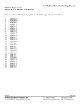
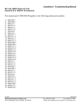
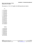
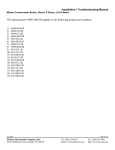
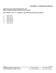
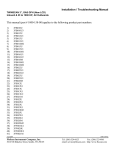
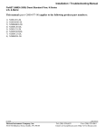
This manual (part # 4001-010-00) applies to the following product part numbers:
1)
2)
3)
4)
5)
6)
7)
8)
9)
10)
11)
12)
13)
14)
15)
16)
17)
18)
19)
20)
21)
22)
23)
24)
25)
26)
27)
28)
29)
30)
31)
32)
33)
34)
35)
36)
37)
38)
39)
40)
41)
42)
5232-231-1
5232-231-1M
53080-231-1
53080-231-2
53100-231-1
53100-33C-1
53100-33C11
5320-20B-1
5320-20B-2
5332-20B-1
5332-231-1
5332-231-2
5350-231-11
54020-20A-1
54020-20A-2
54040-20A-1
54040-20A-2
5405-20A-1
5405-20A-2
54080-20A-1
54080-20A-2
5410-20A-1
5410-20A-2
5420-20A-1
5420-20A-2
55040-20B-1
55040-231-1
55040-231-2
55080-20B-1
55080-20B-2
55080-231-1
55080-231-2
5510-20B-1
5510-20B-2
5510-231-1
55100-231-1
55100-231-2
55160-231-1
55160-231-2
55160-23121
55161-231-1
55161-231-2
5/20/2004
FloScan Instrument Company, Inc.
3016 NE Blakeley Street, Seattle, WA 98105
4001-391-00
Tel: (206) 524-6625
email: [email protected]
Fax: (206) 523-4961
http://www.floscan.com
43)
44)
45)
46)
47)
48)
49)
50)
51)
52)
53)
54)
55)
56)
57)
58)
59)
60)
61)
62)
5520-20B-1
5520-20B-2
5520-231-1
5520-231-2
5532-20B-1
5532-20B-2
5532-231-1
5532-231-1M
5532-231-2
5532-231-2M
5532-231-11
5532-231-21
5550-231-1
5550-231-2
5550-231-11
5550-231-21
56100-33C-1
56100-33C-2
56100-33C11
56100-33C21
3/29/2004
FloScan Instrument Company, Inc.
3016 NE Blakeley Street, Seattle, WA 98105
4001-391-00
Tel: (206) 524-6625
email: [email protected]
Fax: (206) 523-4961
http://www.floscan.com
!
INSTALLATION PLANNING
!
READ ME FIRST - Mechanical & Electrical Installation Planning Saves Time!
FloScan systems are not difficult to install. Installing one requires only basic electrical & mechanical skills. With forethought and
planning, your system will be installed with few problems.
I. Installation Preparation:
Review the mechanical installation instructions, then survey your vessel. Determine where the Sensor(s), Pulsation Damper(s), (if
used) Switches and Instruments are to be mounted. Place them at their approximate locations. Measure fuel line lengths between
system components, (Primary Filter, Sensor(s), Damper(s), Engine, and Fuel Tank). Determine fitting sizes and type of fittings needed
for each plumbing connection, (JIC, SAE, NPT, NPTF, or Hose Barb).
FloScan Gasoline, “Hi-Flo” system components have ½” Female NPT ports.
FloScan Gasoline, “Lo-Flo” system components have ¼” Female NPT ports.
Review the electrical installation instructions. Open and survey your vessels wire ways and run 3-conductor cables from each sensor
to the instrument. Tachometers require 1 or 2 additional conductors. If there’s an existing tachometer, its signal wires can be used.
II. Mechanical Installation:
Install or mount the Sensor(s), Pulsation Damper(s), (If required) Instruments and Switches, (Reset, MPG, Port/Starboard, Synch).
III. Plumbing:
Mount sensor(s) where they’re to be installed. On installations using Fabric Braid A-1 Fuel Hose install the correct HB X MNPT
fitting into each sensor. Always assemble fittings using a fuel proof pipe thread sealant. Never use Teflon Tape. Use a hose cutter or
knife to cut the fuel hose. Next install the hose onto the barb fittings. Hose should not be twisted, have adequate slack, an ample radius
at all bends and be supported at reasonable distances, approximately 2-4 feet. When clamping hose onto the barbs, use 2 narrow or 1
wide stainless hose clamp on each hose end.
Wire Braid A-1 Aeroquip Type Fuel Hose or Hydraulic Hose: Mount the sensor(s) or sensor assemblies where they’re to be
installed. Mark the hose where it is to be cut. Remove hose and bring it to a hydraulic shop. Have them cut the hose and install hose
ends. Reinstall the hoses and install the correct fitting into each sensor or sensor assembly. Always assemble fittings using a fuel proof
pipe thread sealant. Never use Teflon Tape. Hoses should not be twisted, have adequate slack, an ample radius at all bends and be
adequately supported at reasonable distances, approximately 2-4 feet. AP-50 copper sealing washers, (Connie Seals) or Flaretite seals
may be required to seal JIC & SAE fittings.
IV. Electrical Installation:
Run cables between Sensor(s) and Instrument(s). Cables must be adequately supported at reasonable distances, approximately 2-4
feet. Wire Terminations—Referring to the wiring diagram. Connect Sensor, Instrument and Switches to their respective wires with
crimp type butt or ring connectors. Always cover connectors and wire ends with heat shrink tubing.
V. System Start-Up:
Prime the fuel system and check for leaks. Start and run your engines. Look for leaks and other installation problems. If system is not
operating properly refer to the Troubleshooting Instructions and correct any deficiencies.
5/25/2004
FloScan Instrument Company, Inc.
3016 NE Blakeley Street, Seattle, WA 98105
4001-386-01D
Tel: (206) 524-6625
Fax: (206) 523-4961
email: [email protected] http://www.floscan.com
VI. Calibration:
When system is running properly, refer to the calibration instructions and calibrate your system.
USCG approved fuel hose with either fabric or wire reinforcing braid meet the following standards:
Hose Marking
USCG Type A-1
USCG Type A-2
USCG Type B-1
USCG Type B-2
Permeation Rating
100g/m²/24hrs.
300g/m²/24hrs.
100g/m²/24hrs.
300g/m²/24hrs.
2½ Minute Fire Test
Required
Required
Not Required
Not Required
Table I
Installation Do’s & Don’ts
Do
Don’t
Use a Fuel Proof Pipe Thread Sealant when
assembling fittings into fuel system components,
(Locktite PST, Leak-Lock, or equivalent).
Never use Teflon Tape!
Use thin wall, low pressure, full flow type NPT or
NPTF hose barb fittings.
Don’t use Push-Lok, or Barb-Tite fittings.
Avoid using JIC or SAE swivel fittings. If used
always install copper conical sealing washers,
(Connie seals) or fitting seals on fittings.
Double clamp all hose barb fittings.
Avoid using 90º elbow fittings.
Install Sensor(s) at a low point in the fuel system, as
far from the engine as practical. Fuel must travel, If possible, avoid bolting or mounting sensor(s)
“Up-hill” slightly after leaving the sensor. Verify directly onto the engine.
correct orientation and fuel flow direction.
Connect all, “Ground” wires to a Ground Buss, or
directly to the Battery’s Negative Terminal. Connect Never connect Instrument or Sensor “Ground”
wires to the hull, engine block, or other
or, “Ground” wire shields to the engine block.
machinery.
On Instruments with a GPS interface, connect
Do not connect FloScan’s Data (–) to the GPS
FloScan’s Data (+) to the GPS signal output.
Data (–).
Connect Data (–) to the GPS signal ground.
Always use non-illuminated switches for Totalizer
Reset, Port/Starboard Select, Hours/Synch, and
GPH/MPG.
5/25/2004
FloScan Instrument Company, Inc.
3016 NE Blakeley Street, Seattle, WA 98105
Never use illuminated, or back-lit switches.
4001-386-01D
Tel: (206) 524-6625
Fax: (206) 523-4961
email: [email protected] http://www.floscan.com
Mechanical Installation
Series 5400(0)/ 5500(0)/ 56100/ 7000(0)/ 8000(0)/ 9000(0)/ TwinScan® - GPH Instrument
Gasoline Engines - Inboard/ I/O/ Outboard
FLOW SENSOR INSTALLATION
Flow Sensors must be placed in a horizontal section of fuel line at a low point in the fuel system. Fuel should travel, “Up-hill” when
exiting the sensor. Its outlet should be at least 1 or 2 inches lower than the fuel pump inlet, priming bulb or pulsation damper, (if
used). Pulsation Dampers and Priming Bulbs must also be mounted horizontally. Installing sensor(s) 12” upstream of the fuel pump,
priming bulb or pulsation damper improves system accuracy. Install sensors in a protected location, away from water spray.
Model 20A, 20B, 231, & 233C gasoline sensors must be installed downstream of a fuel filter or water separator. On vessels not
equipped with off engine filters, we suggest installing a Flow Ezy model ILA-02 filter with 238 micron screen directly to the 20A,
20B or 231 Low-Flow Sensors’ inlet. Use model 4ILA-04 with 595 micron screens with High Flow 233C Sensors’.
Flow Ezy can be reached at (800) 237-1165.
Caution: NEVER install sensor(s) downstream of an engine mounted fuel filter. NEVER use Teflon Tape when installing
sensors. Teflon Tape can jam a sensor’s rotor. Instead, always use a fuel proof pipe thread sealant.
For proper system operation, Carburetor Inboard & I/O Engines having diaphragm fuel pumps require Gasoline Pulsation
Dampers. FloScan Systems are not shipped with Pulsation Dampers’ as carburetor Inboard and I/O engines are no longer in
production. If you have a Carburetor Inboard or I/O engine, Pulsation Dampers can be purchased factory direct. Standard
Flow Dampers’ are $30.00 each and High Flow Dampers’ are $45 each. Damper orders ship via UPS-3 day on purchase date.
Prices include shipping and handling.
To order please contact FloScan Sales or Service, (206) 524-6625, X-306, 316, 309, or 302.
E-mail: [email protected], or [email protected].
The following engine types DO NOT require Pulsation Dampers:
•
•
•
Outboard Gasoline Engines Including Ficht, Optimax, 2 & 4-Cycle.
Closed Loop EFI Gasoline Outboard, Inboard, and I/O Engines.
Open Return EFI Gasoline Inboard and I/O Engines.
•
Sensors are marked with orientation and fuel flow arrows. They must be installed with these arrows pointing in the right direction.
Standard-Flow Pulsation Damper
20A/ 20B/ 231 SENSOR
Outlet
Inlet
ARROW UP
Fuel Flow Direction
5/19/2004
FloScan Instrument Company, Inc.
3016 NE Blakeley Street, Seattle, WA 98105
ARROW UP
7000-036-00J
Tel: (206) 524-6625
Fax: (206) 523-4961
email: [email protected] http://www.floscan.com
High-Flow Pulsation Damper
233C SENSOR
Outlet
Inlet
ARROW UP
•
Install sensor(s) with orientation arrows pointing UP Ï. Fuel must enter through the port marked IN or with an inward pointing
Î fuel flow arrow, and exit through the port marked OUT or with an outward pointing Î arrow.
•
The sensor must be installed horizontally at a low point in the fuel system. When fuel exits the sensor it must travel up-hill
slightly. One or two inches of vertical rise is adequate, more is ok.
•
The sensor must be installed downstream of, and protected by a screen, filter, or water separator. Sensors are tolerant of fine
debris. A coarse screen, (up to 800 microns) or water separator is all that is required.
•
It is recommended that the sensor be installed between the fuel filter and fuel pump inlet. There should be at least twelve inches
of fuel hose, (more is ok) between the sensor and fuel pump inlet.
•
If required, the pulsation damper must be installed horizontally, with its orientation arrow pointing up, (refer to fuel flow
schematics below).
•
Minimize the number of 90º elbows and pipe fittings. Excessive use may create a high vacuum, fuel restricting pressure drop
across the fuel system. Whenever possible, use a large radius hose bend instead of elbows. Refer to the engine owner’s manual for
maximum fuel pump vacuum. A vacuum gauge can be used to confirm that the system is within limits.
•
If swivel fittings are used, (JIC or SAE) their mating surfaces should be sealed with AP 50 Copper Conical Sealing Washers or
Flaretite Fitting Seals. Seals and sealing washers can be purchased through Fittings Inc. in Seattle, WA (206) 767-4670, 1-800552-0632, or a local hydraulic supply house.
CAUTION, DO NOT OVER TIGHTEN FLOW SENSOR FITTINGS. Over-tightening may crack the sensor’s body. Cracks
cause leaks and fuel leaks sometimes cause catastrophic explosions and fire.
Torque pipe thread fittings to a maximum of 15 ft-LB, (180 inch-LB) or two full turns beyond hand tight, (Whichever comes first).
Use a fuel proof pipe thread sealant be used when installing fittings into the flow sensors, (LockTite PST, Rector Seal, Jomar, etc).
INSTRUMENT INSTALLATION
•
Before cutting holes in your Instrument Panel, verify that the instrument will be installed approximately 12” away from the
compass, and in a shaded location out of direct sunlight. Mounting it within 12” of a compass may interfere with compass
operation. Direct sunlight may cause the LCD display to temporarily turn black due to heat.
Instrument Series
5400(0), 5500(0)
7000(0), 8000(0), 9000(0), TwinScan®
5/19/2004
FloScan Instrument Company, Inc.
3016 NE Blakeley Street, Seattle, WA 98105
Cutout Size
3 1/16”
3 3/8”
Table 1
Instrument Depth
3” – Console Panel Thickness
2 ½” – Console Panel Thickness
7000-036-00J
Tel: (206) 524-6625
Fax: (206) 523-4961
email: [email protected] http://www.floscan.com
Standard-Flow Gasoline System Schematics
FUEL TANK
FUEL
FILTER
1" to 2" Minimum
20A/ 20B/ 231 Vertical Rise
Flow Sensor
Vane, Gear, Gear-Rotor
Electric
Fuel Pump
(EFI & Carburetor Engines)
ENGINE
ARROW UP
12" Minimum Distance:
A-1 Fabric Braid
Flexible Fuel Line Preferred
Outboard Motor
Diaphragm
Fuel Pump
FUEL TANK
FUEL
FILTER
20A/ 20B/ 231
Flow Sensor
Priming
Bulb
1" to 2" Minimum
Vertical Rise
ENGINE
ARROW UP
12" Minimum Distance:
A-1 Fabric Braid
Flexible Fuel Line Preferred
Engine Driven
Diaphragm Fuel Pump
(Carbureted Inboards and I/O's)
Pulsation
Damper
1" to 2" Minimum
Vertical Rise
FUEL TANK
FUEL
FILTER
20A/ 20B/ 231
Flow Sensor
ENGINE
ARROW UP
12" Minimum Distance:
A-1 Fabric Braid
Flexible Fuel Line Preferred
5/19/2004
FloScan Instrument Company, Inc.
3016 NE Blakeley Street, Seattle, WA 98105
7000-036-00J
Tel: (206) 524-6625
Fax: (206) 523-4961
email: [email protected] http://www.floscan.com
High-Flow Gasoline Fuel Flow Schematics
FUEL TANK
FUEL
FILTER
233
Flow Sensor
1" to 2" Minimum
Vertical Rise
Vane, Gear, Gear-Rotor
Electric
Fuel Pump
(EFI & Carburetor Engines)
ENGINE
12" Minimum Distance:
A-1 Fabric Braid
Flexible Fuel Line Preferred
Pulsation
Damper
Engine Driven
Diaphragm Fuel Pump
(Carbureted Inboards and I/O's)
1" to 2" Minimum
Vertical Rise
FUEL TANK
FUEL
FILTER
233
Flow Sensor
ENGINE
12" Minimum Distance:
A-1 Fabric Braid
Flexible Fuel Line Preferred
5/19/2004
FloScan Instrument Company, Inc.
3016 NE Blakeley Street, Seattle, WA 98105
7000-036-00J
Tel: (206) 524-6625
Fax: (206) 523-4961
email: [email protected] http://www.floscan.com
ELECTRICAL
Series 5400(0)/5500(0)/56100/5800(0)/6500(0)/6600(0) AccuTroll & CruiseMaster,
All Multi Function Instruments, & TwinScan®
SET UP
Wire & Switches: Use 18 AWG stranded wire on runs under 50’. For runs over 50’ use 16 AWG. Shielded wire is recommended for
all Diesel systems and suggested for Inboard & I/O gasoline systems. Always, “Ground” the wire shield or shield drain wires in the
engine room by connecting them to the bonding system or engine block. The double wiring harness for twin engine Pulse/NMEA
Diesel installations is included in all, (97/9800(0)) kits. FloScan suggests using J-Boxes, Terminal Blocks, and three conductor cables
between diesel sensors and instrument to make wiring easier.
Install Single Pole Single Throw (SPST) switches for Totalizer Reset, Port–Starboard Select, Engine Hours / Synchronizer, and GPH /
MPG, (switches are not included with kit). To determine which switch types are required for your system, refer to the table below. All
instruments except TwinScan Tachometers require a totalizer reset switch.
SYSTEM
2500
5400(0)
5500(0)/56100
5800(0)
6500(0)/6600(0)
65/6600(0) Cummins PT
7000/8000 Gasoline MFI
75/7600(0) Diesel MFI
9000 Gasoline MFI
95/96/97/9800(0)
TwinScan GPH Meter
TwinScan Tachometer
TwinScan GPH & Tachometer
NA = Not Applicable
TOTALIZER RESET
SPST or Momentary ON
SPST or Momentary OFF
SPST or Momentary OFF
SPST or Momentary OFF
SPST or Momentary OFF
SPST or Momentary OFF
SPST or Momentary ON
SPST or Momentary ON
SPST or Momentary ON
SPST or Momentary ON
SPST or Momentary ON
NA
SPST or Momentary ON
PORT/STBD
Twin Engine Systems
SPST
SPST
SPST
NA
NA
SPST
SPST
NA
SPST
NA
NA
NA
NA
HOURS/
SYNCH
NA
NA
NA
NA
NA
NA
SPST
NA
SPST
NA
NA
NA
NA
GPH/
MPG
NA
NA
NA
NA
NA
NA
NA
NA
SPST
SPST
NA
NA
NA
MPG/
SYNCH
NA
NA
NA
NA
NA
NA
NA
NA
NA
NA
NA
NA
SPST
Grounding: Each Black sensor wire must be connected directly to the Black, “Instrument Ground” wire. Use a single wire to connect
the Black wire junction to the battery’s negative terminal, or a ground buss.
Power: FloScan Instruments & sensors operate on 9 to 12 VDC. Voltages exceeding 16 VDC will damage equipment. 24 & 32 VDC
systems must be reduced to 12 VDC. Two different types of voltage reducers are available through FloScan.
WIRE CONNECTIONS
Installation: Connect wires one at a time and install heat shrink tubing before proceeding to
the next wire, (refer to diagram). Connect ground wires first, (BLACK instrument ground
wire to the BLACK sensor wires). Connect this junction to the battery’s negative terminal
or the ground buss. Connect all other wires leaving the Red power wires for last to prevent
short circuits during installation.
Splicing: Splice or join individual wires per the diagram. Slide heat shrink tubing over the
splices to prevent shorts. Do not seal splices until the installation is finished and has been
tested.
1. Slide heat shrink tubing
over one wire.
2. Insert wire ends into butt splice.
3. Crimp butt splice.
4. Slide heat shrink tubing
over butt splice.
HEAT
5. Apply heat.
An adequate number of crimp-on connectors and heat-shrink tubing are included with
system. The heat-shrink is a special type that will bond to wire insulation and make a
watertight connection. See diagram for proper tubing application. Crimp-on connectors are sized for 18 or 20 gauge stranded wire.
5/21/2004
FloScan Instrument Company, Inc.
3016 NE Blakeley Street, Seattle, WA 98105
4001-100-00I
Tel: (206) 524-6625
Fax: (206) 523-4961
email: [email protected] http://www.floscan.com
Tachometer Wiring Information applies only to MFI & TwinScan Instrument Tachometers
Tachometer signal wires on MFI & TwinScan Tachometers should be shielded.
For proper tachometer operation on gasoline EFI engines, (especially outboards) the engine Ground wire must be physically
connected to the MFI or TwinScan instrument ground wire.
Note: FloScan recommends using dedicated 18 AWG shielded cable for tachometer signal wire connections. Always, “Ground” wire
shields or the shield drain wire in the engine room by connecting to the bonding system or engine block.
MULTI FUNCTION & TWINSCAN INSTRUMENT TACHOMETERS for
CARBURETOR & CLOSED LOOP EFI GASOLINE ENGINES with POINTS or STANDARD ELECTRONIC IGNITIONS
Inboard, & I/O Engines: Connect the YELLOW wire from pin # 8 to the distributor coil’s negative terminal. On twin engine systems
the Yellow wire from pin # 8 connects to the port engine, the VIOLET wire from pin # 16 to starboard.
Outboard Engines: Outboard tachometers are connected to either the engine alternator or tachometer signal wire. Connect the
YELLOW wire from pin # 8 to the engine alternator or tachometer signal wire. On twin engine systems the Yellow wire from pin # 8
connects to the port engine, the VIOLET wire from pin # 16 to starboard.
MULTI FUNCTION & TWINSCAN INSTRUMENT TACHOMETERS for
CLOSED LOOP EFI GASOLINE ENGINES with CPU IGNITION SYSTEMS
Inboard, I/O, & Outboard Engines: Connect the YELLOW wire from pin # 8 to the engines’ tachometer signal wire. On twin engine
systems the Yellow wire from pin # 8 connects to the port engine, the VIOLET wire from pin # 16 to starboard.
Outboard Engines: Connect the YELLOW wire from pin # 8 to the engines’ tachometer signal wire. On twin engine systems the
Yellow wire from pin # 8 connects to the port engine, the VIOLET wire from pin # 16 to starboard.
MULTI FUNCTION INSTRUMENT TACHOMETERS for
OPEN RETURN EFI GASOLINE ENGINES with CPU IGNITION SYSTEMS
Inboard & I/O Engines: Connect the YELLOW wire, pin # 8 to the engines’ tachometer signal wire. Connect the VIOLET wire, pin #
16 to ground.
•
MULTI FUNCITON INSTRUMENT TACHOMETERS - DIESEL ENGINES
Keep existing tachometer: Connect the YELLOW and VIOLET wires to the existing tachometer signal wires. If one lead is
grounded at the pickup or alternator, connect the YELLOW wire to the tachometer signal wire. Connect the VIOLET wire to a
ground buss.
•
Replace existing tachometer: Connect the YELLOW and VIOLET wires to the existing magnetic pickup or signal generator. If
one lead is grounded at the pickup or alternator, connect the YELLOW wire to the existing signal wire terminal at the tachometer
and connect the VIOLET wire to a ground buss.
•
Install as a new tachometer. On engine alternator installations, connect the YELLOW wire to the tachometer output terminal
(usually marked “tach” or “sig”) and connect the VIOLET wire to a ground buss. For mechanically driven A-C signal generators
and magnetic pickups, connect the YELLOW wire to one terminal and the VIOLET wire to the other.
•
TWINSCAN INSTRUMENT TACHOMETERS – DIESEL ENGINES
Connect the YELLOW wire to one terminal the Port tachometer sender, (AC signal generator, Magnetic pickup, or the engines’
alternators tach or sig terminal). Connect the VIOLET wire to the Starboard sender. The tachometer senders’ second terminal
must be grounded.
FINAL ACTIONS
Check Electrical Installation: Test all connections. Support and secure all dangling wires. Start engine and calibrate system.
5/21/2004
FloScan Instrument Company, Inc.
3016 NE Blakeley Street, Seattle, WA 98105
4001-100-00I
Tel: (206) 524-6625
Fax: (206) 523-4961
email: [email protected] http://www.floscan.com
WIRING DIAGRAM
Series 5400(0)/5500(0)/56100 AccuTroll & CruiseMaster
GPH Instrument with LCD Totalizer
WIRE COLOR
RED
GREEN
BLACK
BLUE
WHITE
BROWN
WIRING LEGEND
FUNCTION
Ignition + 12VDC
Totalizer Memory Constant + 12VDC
Instrument Ground
To PORT/STARBOARD switch
PORT signal
STARBOARD signal
Single Sensor Installation
Totalizer Memory
Constant+ 12 VDC Source
(Negligible battery draw)
1/2 amp fuse
BLACK
WHITE
RED
GREEN
Totalizer
Reset Switch
(momentary OFF)
* Do not use Back-lit, or Illuminated switches
BLUE
BROWN
(not connected in single sensor installations)
1/2 amp fuse
To Ignition Switch
(key ON = + 12VDC)
BLACK
To
Illumination
Circuit
+ 12VDC
(not connected, diagnostic wire)
RED
R
W
WHITE
CABLE
B
BLACK
Flow
Sensor
Battery (-) buss
(for twin installations, please see reverse side)
5/20/2004
FloScan Instrument Company, Inc.
3016 NE Blakeley Street, Seattle, WA 98105
4001-167-00G
Tel: (206) 524-6625
email: [email protected]
Fax: (206) 523-4961
http://www.floscan.com
Twin Engine Installations
Option #1
Port Engine
key switch
Starboard Engine
key switch
1/2 amp fuse
(2 places)
1/2 amp fuse
GREEN
RED
To Port sensor
BLUE
WHITE
BROWN
To
Illumination
Circuit
+ 12VDC
BLACK
RED
BLACK
Totalizer
Reset Switch
RED
To
Instrument
RED
To Starboard sensor
(momentary OFF)
* Do not use Back-lit, or
Illuminated switches
Totalizer Memory
Battery (-) buss
Constant
IN4005
DIODES
Option #2
+ 12 VDC
Source
To PORT or STARBOARD ignition switch
(key ON = + 12VDC)
(Negligible battery draw)
BLACK
1/2 amp fuse
RED
To Port sensor
RED
To
Instrument
RED
(OFF)
(ON)
STARBOARD
BLUE
To Starboard sensor
See option 1 and 2 diagram for instructions.
Option 1 is used to power the Port/Stbd side
independently of each other, using it's own
ignition switch.
PORT
CABLE
SPST
switch
* Do not use Back-lit, or
Illuminated switches
BLACK
Option 2 is used to power the FloScan system
using one ignition switch.
PORT
B
BLACK
R
R
B
W
B
CABLE
W
Flow
Sensor
WHITE
RED
See option 1 and 2
STARBOARD
R
R
BROWN
WHITE
B
B
W
CABLE
B
5/20/2004
FloScan Instrument Company, Inc.
3016 NE Blakeley Street, Seattle, WA 98105
W
Flow
Sensor
4001-167-00G
Tel: (206) 524-6625
email: [email protected]
Fax: (206) 523-4961
http://www.floscan.com
CALIBRATION
Series 5400(0)/5500(0)/56100 AccuTroll & CruiseMaster
There are nine, “Dip” switches on the back of your 5400(0)/5500(0)/56100 Series Instrument. Switches 1-4 are used for instrument
calibration (Refer to Table I). Switches 6 - 9 select the flow sensor required by your engine, (Refer to Table II) Switch 5 is used to
dampen the instrument needle in heavy seas. When turned on, switch 5 slows the needles’ response rate.
Totalizer Calibration:
1.
2.
3.
4.
5.
Top off the fuel tank(s) and reset the totalizer to, “0”.
Operate the boat the way that you normally would, consuming at least 20 gallons of fuel.
Return to the fuel dock and top off your fuel tank(s).
Compare the totalizer reading to the fuel pump reading.
Calculate the percentage difference using the following formula:
Difference in Gallons
x 100
Totalizer Reading
6.
Turn ON the combination of switches 1, 2 and/or 3 which equal that difference.
Example:
You determine the totalizer reading is 6.5% lower than what actually was actually used. The combined percentage total of
switches 1 (2%) and 2 (4%) is 6%. Turn switches 1 and 2 and “4” ON.
Switch #4 remains OFF if the totalizer reads higher than the actual fuel used, and is turned ON if the totalizer reading is less than
the fuel used.
Switch position
(1)
(2)
(3)
(4)
(5)
results when turned on
2%
4%
8%
OFF Totalizer reading higher
ON
Totalizer reading lower
OFF Normal meter damping
ON
Heavy meter damping
Table I
Flow Sensor selection
Used to calibrate
ON
1
2
3
4
5
6
7
8
9
Sensor
Example: Totalizer reading 6% higher with sensor
Switches
(7)
(8)
(9)
* 20A
ON
OFF
OFF
20B
OFF
OFF
OFF
231
OFF
OFF
OFF
233C
ON
OFF
OFF
Table II
* Instruments programmed for the 20A sensor cannot be used with 20B, 231 or 233C sensors.
(6)
OFF
OFF
ON
ON
NOTE:
1.
2.
3.
Adjusting instrument calibration affects both Totalizer and GPH readings.
Drastically changing operating habits (from mostly cruising to mostly trolling) may slightly effect totalizer accuracy.
On custom calibration instruments, at least one of the switches from 1-5 must be OFF. If switches 1-9 are all turned
ON, the instrument automatically goes into diagnostic mode.
5/19/2004
FloScan Instrument Company, Inc.
3016 NE Blakeley Street, Seattle, WA 98105
4001-009-05I
Tel: (206) 524-6625
Fax: (206) 523-4961
email: [email protected] http://www.floscan.com
COMMON ACCUTROLL & CRUISEMASTER SYSTEM QUESTIONS
1. How is the 5400(0)/5500(0)//56100, twin engine system wired so that either engine will power the meter.
Use two diodes, (1N4005) and wire as per the sketch below.
PORT flow sensor
RED wire to
Cruisemaster
1N4005
PORT key switch
1N4005
STBD key switch
STBD flow sensor
2. What type of switch is used for the PORT/STBD select switch?
A single pole single throw (SPST) On/Off switch. When the switch is turned OFF, the needle shows the Port engine consumption.
When turned on, the needle shows Starboard engine consumption.
3. How do I reset the totalizer?
Totalizer memory is powered through the Green wire. If Green wire power is interrupted for 10-15 seconds the totalizer resets to zero.
Memory is retained as long as 9-15 VDC is maintained between the GREEN and BLACK meter wires.
4. Will, “Pegging” the GPH meter needle hurt the instrument? Will the totalizer record accurately with the needle pegged?
When “Pegged” the needle rests harmlessly against a mechanical stop while the totalizer continues to accurately record consumption.
5. What causes needle fluctuations?
Fluctuating readings are usually caused by one of the following:
•
•
•
•
•
Air bubbles passing through the flow sensor.
Fuel pump pulsations, (Do not install the flow sensor closer than 12” to the fuel pump).
A Sticky or misadjusted carburetor float valve.
A 4 sided, “square” float valve, (installing and properly adjusting a three, (3) sided triangular float valve corrects this problem).
A sticking or chattering anti-siphon valve.
NOTE: Sticking float and anti-siphon valves do not effect system accuracy.
6. Does it make any difference which way the flow sensor(s) are mounted?
YES. There is only one way to install the sensors. Flow sensor(s) must be installed with the fuel flow and orientation arrows pointed
in the right direction for the system to work properly.
7. Will the flow sensor cause fuel starvation?
No, the flow sensors will not cause fuel starvation. Anything put into a fuel line does however have a certain pressure drop across it.
Everything in the fuel line combines to form the systems total pressure drop. If this is more than the fuel pump can tolerate, you must
find a way to reduce the total pressure drop or fuel starvation will occur at higher engine RPM.
8. Will the flow sensor shut off fuel to the engine if it stops working?
FloScan flow sensors are of a FAIL SAFE design. A failure will not restrict fuel flow to the engine, nor will the sensors’ pressure drop
increase even if the rotor stops turning.
5/19/2004
FloScan Instrument Company, Inc.
3016 NE Blakeley Street, Seattle, WA 98105
4001-213-00C
Tel: (206) 524-6625
Fax: (206) 523-4961
email: [email protected] http://www.floscan.com
9. Why isn’t my totalizer as accurate as it could be?
The major causes of inaccurate totalizer readings are:
•
•
•
•
•
Air bubbles in the fuel line caused by vacuum leaks around fuel filter gaskets, and/or improperly sealed plumbing joints.
Incorrect flow sensor installation.
Installing sensor within 12-14” of the fuel pump.
Faulty wiring.
Improper sensor selection and instrument calibration.
10. What do I do if I have a problem?
Most problems are related to improper installation. Step 1 is to review the installation and verify that system components are installed
and wired correctly. Next follow the troubleshooting guide, and record your results. This will most likely lead you to the problem. If
not please call FloScan Technical Support at (800 522-3610) with your test findings. If you did not complete the troubleshooting steps,
you will be asked to do so before calling back.
5/19/2004
FloScan Instrument Company, Inc.
3016 NE Blakeley Street, Seattle, WA 98105
4001-213-00C
Tel: (206) 524-6625
Fax: (206) 523-4961
email: [email protected] http://www.floscan.com
TROUBLESHOOTING
Series 5400(0)/5500(0)/56100 AccuTroll & CruiseMaster GPH/LPH Instrument
BEFORE CALLING FOR ASSISTANCE, COMPLETE THESE TROUBLESHOOTING CHECKS AND RECORD YOUR FINDINGS.
TECHNICAL SUPPORT REQUIRES THIS INFORMATION BEFORE A RETURN AUTHORIZATION WILL BE ISSUED. IT TAKES ABOUT
20 MINUTES AND IS VERY IMPORTANT IN ANALYZING SYSTEM PROBLEMS.
Before starting record the Instrument MODEL # ________________________ and all Switch settings.
ON
OFF
Switch Settings
1
FAULT
Blank LCD Display.
No Back-Lighting.
Low Totalizer Reading, more than 10%.
High Totalizer Readings, more than 10%.
Fluctuating GPH readings.
No GPH or totalizer reading.
No sensor readings.
High sensor readings.
2
3
4
5
6
7
8
9
PROBABLE CAUSE
SEE SECTION:
Wiring
Wiring/bulb failure
Calibration
Sensor orientation/failure
Incorrect/defective sensor
Incorrect switch settings
Suction leak
Suction leak
Low RPM operation
Wiring/Instrument failure
Sensor orientation/failure
Wiring
Sensor failure
Suction leak
Wrong switch settings
Sensor orientation
Section I
Section III
Calibration sheet
Installation Sheet
Operations
Manual page
Section VI
Section VI
Section VIII
Section IV and V
Installation sheet
Section IV and V
Section II
Section VI
Calibration sheet
Section VII
I. INSTRUMENT HEAD DIAGNOSTIC TEST
1.
Referring to the wiring diagram, verify that Instrument & Sensor(s) are wired correctly.
2.
Verify that all wiring connections are tight and not corroded. Check continuity with an ohmmeter.
3.
With power switched ON, measure voltage between the RED and BLACK wires,
(Take readings on the Instrument side of the butt splice connections).
__________VDC
The voltage reading should be between 12 and 14.5 VDC. Proceed to step 4 if it is, if not:
a. Check for voltage between the RED wire and another ground point.
b. If voltage is present, trace along the BLACK wire until its’ open connection is found.
c. If no voltage is present, trace the RED wire until its’ open connection is found.
4.
With switched power ON slide, “Dip” switches 1-9 to the ON, or UP position. This places the
Instrument into diagnostic mode.
NOTE: If the LCD display is blank, verify that the totalizer reset switch, (Connected between the GREEN
wire and +12 volts) is in the ON position. Verify that 12 VDC is present between both switch
terminals and the Black wire. Next check the, “Green wire” fuse.
5/19/2004
FloScan Instrument Company, Inc.
3016 NE Blakeley Street, Seattle, WA 98105
4001-102-00H
Tel: (206) 524-6625
Fax: (206) 523-4961
email: [email protected] http://www.floscan.com
5.
In, “Diagnostic Mode” the totalizer will count at 1 gallon or 1 liter per second. If it does not, the
Instrument is defective.
6.
With the BLUE wire floating, (Disconnected) on single engine systems, or the Port/Starboard select switch set to Port on
twin engine systems, the pointer should read approximately:
5 GPH models
10 GPH models
20 GPH models
32 GPH models
50 GPH models
100 GPH models
7.
4.5
9
18
28
45
90
20 LPH models
40 LPH models
80 LPH models
160 LPH models
500 LPH models
18
35
70
140
450
With the BLUE wire connected to the Instruments’ BLACK wire on single engine systems, or the Port/Starboard select
switch set to Starboard on twin engine systems, the pointer should read approximately:
5 GPH models
10 GPH models
20 GPH models
32 GPH models
50 GPH models
100 GPH models
0.25
0.5
1
2
2
5
20 LPH models
40 LPH models
80 LPH models
160 LPH models
500 LPH models
1
2
5
10
20
NOTE: If readings are significantly Higher or Lower, the Instrument may be defective.
8.
Turn switches 1, 2, 3, 4, 5, 8 and 9 OFF, leave 6 and 7 ON.
9.
Disconnect the WHITE and BROWN wires at the Instrument. Connect a course thread, (½ - 13) or similar non-plated bolt to
the BLACK wire.
10. With the BLUE wire floating, (Disconnected) or Port/Starboard select switch set to Port, lightly run the WHITE wire up and
down the bolt threads. This generates a pulse and should lift the needle off zero. The totalizer should also eventually start
counting. Faster movements give higher readings.
11. With the BLUE wire connected to ground or the Port/Starboard select switch set to Starboard, lightly run the BROWN wire
up and down the threaded bolt as described above. This generates a pulse and should lift the needle off zero. The totalizer
should also eventually start counting. Faster movements give higher readings.
12. If the Instrument passes steps 10 & 11, returns switches 1-9 to their original position and proceed with Part II. If not contact
FloScan Technical Support.
NOTE: Occasionally a good Instrument will fail the, (Bolt scratch test).
II. TEST FLOW SENSOR(S)
1.
2.
3.
With your voltmeter set to a DC scale greater than 14 volts, measure between the RED (+12VDC) and
BLACK (Instrument ground) wires. With engine idling, measure and record the voltage reading.
___________VDC
Move the voltmeters’ negative lead to the WHITE (Signal) wire. With engine idling, measure and record
the voltage reading. It should be approximately 5 to 7 VDC, about ½ of the reading in step 1.
___________VDC
Stop the engine while observing the voltmeter. Readings should fluctuate between a high of 9 to 12 VDC,
and a low of 0 to 4 VDC as the sensors’ turbine slows to a stop.
___________VDC
NOTE: This may not be seen on a digital voltmeter.
5/19/2004
FloScan Instrument Company, Inc.
3016 NE Blakeley Street, Seattle, WA 98105
4001-102-00H
Tel: (206) 524-6625
Fax: (206) 523-4961
email: [email protected] http://www.floscan.com
4.
Move the voltmeters’ negative lead to the BROWN (Signal) wire. With engine idling, measure and record
the voltage reading. It should be approximately 5 to 7 VDC, about ½ of the reading in step 1.
5.
___________VDC
Stop the engine and observe the voltmeter. Voltage readings should fluctuate between a high of 9 to 12
VDC, and a low of 0 to 4 VDC as the Sensors’ turbine slows to a stop.
NOTE: This may not be seen with a digital voltmeter.
6.
The Sensor may be defective if voltage readings in steps 3 & 5 remain constant while the engine is
stopping.
7.
On twin engine systems, try swapping the Brown & White signal wires. Observe the Instrument and see if the
problem shifts sides, or remains on the same side.
With this guide in hand, contact FloScan Technical Support.
III. BACKLIGHTING.
1. Referring to the wiring diagram, check back lighting bulb and Instrument illumination circuit.
IV. CHECK + 12 VDC and GROUND
1.
Turn Instrument power ON, and go to the Instruments’ backside.
2.
Measure between the RED (Power) wire and the BLACK (Instrument ground) wire.
This reading should be approximately 12 VDC, but not lower than 10 VDC.
3.
If 12 VDC is not present, measure between the RED power wire and a known good ground in the
instrument panel. If you measure 12 to 14 VDC between the Red wire and ground, you may have
an instrument ground problem.
4.
__________VDC
__________VDC
If 12 to 14 VDC is not present in steps 2 or 3, check wiring, switches, fuse, and the 12 VDC power source.
V. CONTINUITY TESTING
1.
Continuity testing requires access to the back of the Instrument and an Ohmmeter. It verifies that wires are not
broken, shorted to ground, another wire, or to power. Before starting, secure all power.
2.
Disconnect the WHITE and BLACK wire harness conductors from the WHITE and BLACK Port Sensor
wires. Connect a jumper from the WHITE wiring harness conductor to a known good ground. At the
back of the Instrument, connect an Ohmmeter lead to its’ WHITE wire. Connect the other Ohmmeter lead
to a known, good ground. The Ohmmeter should read approximately 0.1 to 3 Ω.
3. Disconnect the BROWN and BLACK wire harness conductors from the WHITE and BLACK Starboard Sensor
wires. Connect a jumper from the BROWN wiring harness conductor to a known good ground. At the back of the
Instrument, connect an Ohmmeter lead to its’ BROWN wire. Connect the other Ohmmeter lead to a known good
ground. The Ohmmeter should read approximately 0.1 to 3 Ω.
____________
(Ohm Reading)
____________
(Ohm Reading)
VI. PULSATION PROBLEMS
A stiff anti-siphon valve, sticking carburetor float or miss-plumbed Pulsation Damper(s) can cause fluctuating GPH readings. These
are most pronounced at low Rpm’s and tend to disappear around mid throttle. They are annoying, but won’t affect totalizer accuracy.
To eliminate, repair or replace any defective parts, or re-plumb dampers according to the Fuel Flow Schematic Instructions.
5/19/2004
FloScan Instrument Company, Inc.
3016 NE Blakeley Street, Seattle, WA 98105
4001-102-00H
Tel: (206) 524-6625
Fax: (206) 523-4961
email: [email protected] http://www.floscan.com
VII. FINDING FUEL SYSTEM VACUUM LEAKS
Fluctuating GPH and High Totalizer Readings are usually caused by a small vacuum leak between the fuel tank and fuel pump inlet.
Fluctuations tend to be between 2 and 4 GPH. These vacuum leaks also affect totalizer accuracy, causing it to read 15 to 100% high.
Larger leaks produce greater fluctuations and higher readings. They generally do not affect engine performance.
Finding suction leaks can be time-consuming. When approached properly, they can usually be found and repaired quickly. Two
common places for suction leaks to occur are at the primary fuel filter - water separator, and/or a loose valve stem packing nut.
Remove the filter housing and coat all o-rings, gaskets and sealing surfaces with a medium to heavy grease, (Do not use oil) and
reassemble. Grease all valve stem packings and gently tighten gland nuts. Don’t over tighten, valve handles should turn freely.
Tighten all hose clamps and compression fittings. Don’t over tighten. Run the engine for 5 to 10 minutes observing GPH readings. If
you’ve found the problem, fluctuations should be reduced to less than ½ GPH.
If the problem persists, temporarily install a clear piece of fuel resistant hose downstream of the forward flow sensor. Run the engine
and watch for a stream of small bubbles in the clear hose, or an occasional larger bubble. Sometimes shining a light through the hose
makes bubbles easier to see.
Observe the clear hose while shaking the fuel lines. If the bubble stream continually increases or decreases you’ve found the leak area.
Repair or replace as needed. If this occurs one-time, you probably dislodged some trapped air.
If the leak hasn’t been found, the last step is to inspect each pipe joint. Thread sealant should be visiable around each joint. If not, that
joint is suspect and must be resealed. After resealing run the engine for a few minutes to purge any remaining air. There should now
be bubble free fuel running through the clear hose. If bubbles are still present a leak was missed. Recheck your work. After all the
leaks are stopped, remove the clear hose.
VIII. FUEL FILTERS
A dirty fuel filter, or one that is too fine (1-25 micron) will draw vapor bubbles out of the fuel, causing fluctuations and high readings.
Replace it with a new 30-micron or coarser filter.
IX. FLOW SENSOR ORIENTATION
Sensor orientation is critical for proper operation. All Sensors have their inlet and outlet ports clearly marked (IN / OUT or Î Î).
This identifies fuel flow direction. The Sensor must be, “Plumbed” correctly for it to operate properly. There is an additional single
arrow on the Sensor body. It is crucial that this single arrow points up Ï.
X. LOW RPM OPERATION
At idle, under a no load condition, it is common for GPH readings to fluctuate slightly. These fluctuations are caused by the engine
governor regulating fuel flow to maintain a steady engine RPM.
This concludes Instrument and Sensor testing. If problems persist, contact FloScan Technical Support.
5/19/2004
FloScan Instrument Company, Inc.
3016 NE Blakeley Street, Seattle, WA 98105
4001-102-00H
Tel: (206) 524-6625
Fax: (206) 523-4961
email: [email protected] http://www.floscan.com