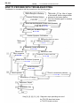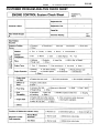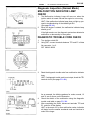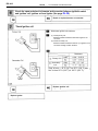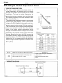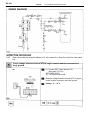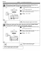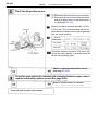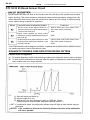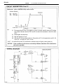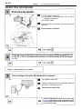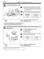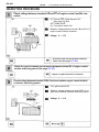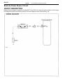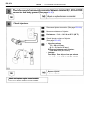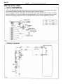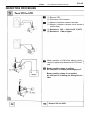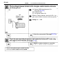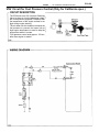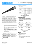
1
EG–381
2JZ–GE ENGINE TROUBLESHOOTING
EG–382
ENGINE
–
2JZ–GE ENGINE TROUBLESHOOTING
HOW TO PROCEED WITH TROUBLESHOOTING
Troubleshoot in accordance with the procedure on the following pages.
Vehicle Brought to Workshop
Titles inside
are titles of pages
in this manual, with the page number
indicated in the bottom portion.
See the indicated pages for detailed
explanations.
Customer Problem Analysis
P. EG–783
Check and Clear Diagnostic Trouble Code (Precheck)
P. EG–785, P. EG–387
Setting the Test Mode Diagnosis
P. EG–386
Problem Symptom Confirmation
Malfunction does not occur.
Malfunction
occur.
Symptom Simulation
P. IN–24
Diagnostic Trouble Code Check
P. EG–386
Normal code
Malfunction code
Basic Inspection
Diagnostic Trouble Code Chart
P. EG–388
P. EG–400
Matrix chart of Problem Symptoms
P. EG–408
Circuit Inspection
P. EG–409
Parts Inspection
Check for intermittent problems
P. EG–399
Identification of Problem
Adjustment, Repair
Confirmation Test
Step [2], [3], [6], [11], [14]: Diagnostic steps permitting the use of
the TOYOTA hand–held tester
or TOYOTA break–out–box.
EG–383
ENGINE
–
2JZ–GE ENGINE TROUBLESHOOTING
CUSTOMER PROBLEM ANALYSIS CHECK SHEET
EG–384
ENGINE
–
2JZ–GE ENGINE TROUBLESHOOTING
DIAGNOSIS SYSTEM
DESCRIPTION
The ECM contains a built–in self–diagnosis system by which
troubles with the engine signal network are detected and a Malfunction Indicator Lamp on the instrument panel lights up.
By analyzing various signals as shown in a later table (See page
EG–388) the Engine Control Module (ECM) detects system malfunctions relating to the sensors or actuators.
In the normal mode, the self–diagnosis system monitors 18
(California specification vehicles) or 17 (except for California and
Canadian specification) items, indicated by code No. as shown in
EG–388. A malfunction indicator lamp informs the driver that a
malfunction has been detected. The lamp goes off automatically
when the malfunction has been repaired, but the diagnostic
trouble code(s) remains stored in the ECM memory (except for
code Nos. 16 and 53). The ECM stores the code(s) until it is
cleared by removing the EFI No. 1 fuse with the ignition switch
OFF.
The diagnostic trouble code can be read by the number of blinks
of the malfunction indicator lamp when TE1 and E1 terminals on
the data link connector 1 or 2 are connected. When 2 or more
codes are indicated, the lowest number (code) will appear first.
In the test mode, 12 (California specification vehicles) or 11 (except for California and Canadian specification vehicles) items, indicated by code No. as shown in EG–388 are monitored. If a malfunction is detected in any one of the systems indicated by code
Nos. 13, 21, 22, 24, 25, 26, 27, 28, 35, 41, 71 and 78 (California
specification vehicles) or 13, 21, 22, 24, 25, 28, 35, 41, 71 and 78
(except for California and Canadian specification vehicles) the
ECM lights the malfunction indicator lamp to warn the technician
that a malfunction has been detected. In this case, TE2 and E1
terminals on the data link connector 2 should be connected as
shown later. (See page EG–386).
In the test mode, even if the malfunction is corrected, the malfunction code is stored in the ECM memory even when the ignition
switch OFF (except code Nos. 43 and 51). This also applies in the
normal mode. The diagnostic trouble mode (normal or test) and
the output of the malfunction indicator lamp can be selected by
connecting the TE1, TE2 and E1 terminals on the data link connector 2, as shown later.
A test mode function has been added to the functions of the self–
diagnosis system of the normal mode for the purpose of detecting
malfunctions such as poor contact, which are difficult to detect in
the normal mode. This function fills up the self–diagnosis system.
The test mode can be implemented by the technician following the
appropriate procedures of check terminal connection and operation described later. (See page EG–386)
EG–385
ENGINE
–
2JZ–GE ENGINE TROUBLESHOOTING
Diagnosis Inspection (Normal Mode)
MALFUNCTION INDICATOR LAMP
CHECK
1.
2.
The Malfunction Indicator Lamp will come on when the
ignition switch is turned ON and the engine is not running.
HINT: If the malfunction indicator lamp does not light up, proceed to troubleshooting of the telltale light RH
(See page BE–48).
When the engine is started, the malfunction indicator lamp
should go off.
If the light remains on, the diagnosis system has detected a
malfunction or abnormality in the system.
DIAGNOSTIC TROUBLE CODE CHECK
1.
2.
Turn ignition switch ON.
Using SST, connect terminals between TE1 and E1 of data
link connector 1 or 2.
SST 09843–18020
3.
Read the diagnostic trouble code from malfunction indicator
lamp.
HINT: If a diagnostic trouble code is not output, check the TE1
terminal circuit (See page EG–484).
4.
5.
As an example, the blinking patterns for codes; normal, 12
and 31 are as shown on the illustration.
Check the details of the malfunction using the diagnostic
trouble code table on page EG–388.
After completing the check, disconnect terminals TE1 and
E1, and turn off the display.
HINT: In the event of 2 or more malfunction codes, indication
will begin from the smaller numbered code and continue in
order to the larger.
EG–386
ENGINE
–
2JZ–GE ENGINE TROUBLESHOOTING
Diagnosis Inspection (Test Mode)
Compared to the normal mode, the test mode has an increased sensing ability to detect malfunctions.
It can also detect malfunctions in the starter signal circuit, the
IDL contact signal of the throttle position sensor, air conditioning signal and park/neutral position switch signal.
Furthermore, the same diagnostic items which are detected
in the normal mode can also be detected in the test mode.
DIAGNOSTIC TROUBLE CODE CHECK
2.
3.
4.
5.
6.
7.
8.
9.
1. Initial conditions.
(a) Battery voltage 11 V or more
(b) Throttle valve fully closed
(c) Transmission in neutral position
(d) Air conditioning switched OFF
Turn ignition switch OFF
Using SST, connect terminals TE2 and E1 of the data link
connector 2.
SST 09843–18020
Turn ignition switch ON.
HINT:
• To confirm that the test mode is operating, check that the
malfunction indicator lamp flashes when the ignition
switch is turned to ON.
• If the malfunction indicator lamp does not flash, proceed
to troubleshooting of the TE2 terminal circuit on page
EG–484.
Start the engine.
Simulate the conditions of the malfunction described by the
customer.
After the road test, using SST, connect terminals TE1 and E1
of the data link connector 2.
SST 09843–18020
Read the diagnostic trouble code on malfunction indicator
lamp on the telltale light RH (See page EG–385).
After completing the check, disconnect terminals TE1, TE2
and E1, and turn off the display.
HINT:
• The test mode will not start if terminals TE2 and E1 are
connected after the ignition switch is turned ON.
• When the engine is not cranked, diagnostic trouble
codes ”43” (Starter signal) output, but this is not
abnormal.
• When the automatic transmission shift lever is in the ”D”,
”2”, ”L” or ”R” shift position, or when the air conditioning
is on or when the accelerator pedal is depressed, code
”51” (Switch condition signal) is output, but this is not
abnormal.
EG–387
ENGINE
–
2JZ–GE ENGINE TROUBLESHOOTING
DIAGNOSTIC TROUBLE CODE CHECK
USING TOYOTA HAND–HELD TESTER
1.
2.
Hook up the TOYOTA hand–held tester to the DLC2.
Read the diagnostic trouble codes by following the prompts
on the tester screen.
Please refer to the TOYOTA hand–held tester operation’s
manual for further details.
DIAGNOSTIC TROUBLE CODE CLEARANCE
1.
After repair of the trouble areas, the diagnostic trouble code
retained in the ECM memory must be cleared out by
removing the EFI No.1 fuse (30A) from R/B No.2 for 10
seconds or more, with the ignition switch OFF.
HINT:
• Cancellation can also be done by removing the negative
(–) terminal cable from the battery, but in this case, other
memory systems (clock, etc.) will also be cancelled out.
•
2.
If it is necessary to work on engine components
requiring removal of the negative (–) terminal cable from
the battery, a check must first be made to see if a
diagnostic trouble code has been recorded.
After cancellation, road test the vehicle to check that a normal
code is now read on the malfunction indicator lamp.
If the same diagnostic trouble code appears, it indicates that
the trouble area has not been repaired thoroughly.
ECM DATA MONITOR USING TOYOTA
HAND–HELD TESTER
1.
2.
Hook up the TOYOTA hand–held tester to the DLC2.
Monitor the ECM data by following the prompts on the tester
screen.
HINT: TOYOTA hand–held tester has a ”Snapshot” function which
records the monitored data.
Please refer to TOYOTA hand–held tester operator’s manual for
further details.
ECM TERMINAL VALUES MEASUREMENT
USING TOYOTA BREAK–OUT–BOX AND
TOYOTA HAND–HELD TESTER
1.
Hook up the TOYOTA break–out–box and TOYOTA
handheld tester to the vehicle.
2. Read the ECM input/output values by following the prompts
on the tester screen.
HINT: TOYOTA hand–held tester has a ”Snapshot” function. This
records the measured values and is effective in the diagnosis of
intermittent problems.
Please refer to TOYOTA hand–held tester/TOYOTA break–out
box operator’s manual for further details.
EG–388
ENGINE
–
2JZ–GE ENGINE TROUBLESHOOTING
DIAGNOSTIC TROUBLE CODE CHART
HINT: Parameters listed in the chart may not be exactly the same as your reading due to type of the instruments
or other factors.
∼
DTC
No.
Number of
MIL Blinks
Diagnostic Trouble Code Detecting Condition
Circuit
Normal
No code is recorded.
No NE or G1 and G2 signal to ECM for 2 sec. or more after cranking
G, NE Signal
(No.1)
Open in “G ” circuit
No NE signal to ECM for 0.1 sec. or more at 1,000 rpm or more
G, NE Signal
(No.2)
NE signal does not pulse 12 times to ECM during the interval between
G1 and G2 pulses
Ignition Signal
No IGF signal to ECM for 6 consecutive IGT signals
A/T Control
Signal
Fault in communications between the engine CPU and A/T CPU in the
ECM
(1)*3 Open or short in heater circuit of main heated oxygen sensor (Fr)
for 0.5 sec. or more
(Main heated *3)
Oxygen
Sensor Signal
(Fr)
(2) (Main heated*3) oxygen sensor (Fr) signal voltage is reduced to
between 0.35 V and 0.70 V for 90 sec. under conditions
(a) ~ (d):
(a)
(b)
(c)
(d)
*3, 4: See page EG–396, 397.
(2 trip detection logic)*4
Engine coolant temp.: Between 80°C (176°F) and
95°C (203°F)
Engine speed: 1,500 rpm or more
Load driving (example A/T in in Overdrive, (5th for M/T),
A/C ON, Flat road, 80 km/H (50 mph))
(Main heated*3) oxygen sensor (Fr) signal voltage:
Alternating above and below 0.45 V
EG–389
ENGINE
–
2JZ–GE ENGINE TROUBLESHOOTING
If a malfunction code is displayed during the diagnostic trouble code check in test mode, check the circuit for
that code listed in the table below (Proceed to the page given for that circuit).
Trouble Area
Malfunction
Indicator
Lamp*1
Test
Normal
Mode
Mode
Open or short in NE, G circuit
Distributor
Open or short in STA circuit
ECM
ON
N.A.
Open or short in NE circuit
Distributor
ECM
ON
N.A.
Memory*2
See page
EG–409
EG–412
Open or short in NE circuit
Distributor
ECM
N.A.
ON
Open or short in IGT or IGT circuit from igniter to ECM
Igniter
ECM
ON
N.A.
EG–413
ECM
ON
N.A.
EG–418
Open or short in heater circuit of main heated oxygen
sensor (Fr)
Main heated oxygen sensor (Fr) heater
ECM
ON
N.A.
EG–419
(Main heated*3) oxygen sensor (Fr) circuit
(Main heated*3) oxygen sensor (Fr)
*1, 2, 3: See page EG–396
EG–390
ENGINE
DTC
No.
Number of
MIL Blinks
Circuit
–
2JZ–GE ENGINE TROUBLESHOOTING
Diagnostic Trouble Code Detecting Condition
Engine Coolant
Temp. Sensor
Circuit
Open or short in engine coolant temp. sensor circuit for 0.5 sec.
or more
Intake Air Temp.
Sensor Signal
Open or short in intake air temp. sensor circuit for 0.5 sec. or
more
(1) (Main heated*3) oxygen sensor voltage is 0.45 V or less (lean)
for 90 sec. under conditions (a) and (b):
(2 trip detection logic)*4
(a) Engine speed: 1,500 rpm or more
(b) Engine coolant temp.: 70°C (158°F) or more
Air–Fuel Ratio
Lean Malfunction
(2)*3 Difference of air–fuel ratio feedback compensation value
between front (no.1 ∼ 3 cylinders) and rear (No.4 ∼ 6
cylinders) is more tan 15 percentage for 20 sec. or more
under conditions (a) and (b):
(2 trip detection logic)*4
(a) Engine speed: 2,000 rpm or more
(b) Engine coolant temp.: Between 60°C (140°F) and
95°C (203°F)
(3)*3 Engine speed varies by more than 15 rpm over the preceding
crank angle period during a period o 20 sec. or more under
conditions (a) and (b):
(2 trip detection logic)*4
(a) Engine speed: Idling
(b) Engine coolant temp.: Between 60°C (140°F) and
95°C (203°F)
*3, 4: See page EG–396 397.
EG–391
ENGINE
–
2JZ–GE ENGINE TROUBLESHOOTING
ÑÑÑÑÑÑÑÑÑÑÑÑÑÑÑÑÑÑÑÑÑÑ
ÑÑÑÑÑÑÑ
ÑÑÑÑÑ
ÑÑÑÑÑ
ÑÑÑÑÑÑÑÑÑÑÑÑÑÑÑÑÑÑÑÑÑÑ
ÑÑÑÑÑÑÑ
ÑÑÑÑÑ
ÑÑÑÑÑ
ÑÑÑÑÑÑÑÑÑÑÑÑÑÑÑÑÑÑÑÑÑÑ
ÑÑÑÑÑÑÑ
ÑÑÑÑÑ
ÑÑÑÑÑ
ÑÑÑÑÑÑÑÑÑÑÑÑÑÑÑÑÑÑÑÑÑÑ
ÑÑÑÑ
ÑÑÑÑÑÑÑÑÑ
ÑÑÑÑÑÑÑ
ÑÑÑÑÑ
ÑÑÑÑÑÑÑÑÑÑÑÑÑÑÑÑÑÑÑÑÑÑ
ÑÑÑÑ
ÑÑÑÑ
ÑÑÑÑÑ
ÑÑÑÑÑ
ÑÑÑÑ
ÑÑÑÑÑ
ÑÑÑÑÑÑÑÑÑÑÑÑÑÑÑÑÑÑÑÑÑÑ
ÑÑÑÑ
ÑÑÑÑÑ
ÑÑÑÑÑÑÑÑÑÑÑÑÑÑÑÑÑÑÑÑÑÑ
ÑÑÑÑ
ÑÑÑÑ
ÑÑÑÑÑ
ÑÑÑÑÑ
ÑÑÑÑÑÑÑÑÑÑÑÑÑÑÑÑÑÑÑÑÑÑ
ÑÑÑÑ
ÑÑÑÑ
ÑÑÑÑÑ
ÑÑÑÑÑ
ÑÑÑÑÑÑÑÑÑÑÑÑÑÑÑÑÑÑÑÑÑÑ
ÑÑÑÑ
ÑÑÑÑ
ÑÑÑÑÑ
ÑÑÑÑÑ
ÑÑÑÑ
ÑÑÑÑÑ
ÑÑÑÑÑÑÑÑÑÑÑÑÑÑÑÑÑÑÑÑÑÑ
ÑÑÑÑ
ÑÑÑÑÑ
ÑÑÑÑÑÑÑÑÑÑÑÑÑÑÑÑÑÑÑÑÑÑ
ÑÑÑÑ
ÑÑÑÑ
ÑÑÑÑÑ
ÑÑÑÑÑ
ÑÑÑÑÑÑÑÑÑÑÑÑÑÑÑÑÑÑÑÑÑÑ
ÑÑÑÑ
ÑÑÑÑ
ÑÑÑÑÑ
ÑÑÑÑÑ
ÑÑÑÑÑÑÑÑÑÑÑÑÑÑÑÑÑÑÑÑÑÑ
ÑÑÑÑ
ÑÑÑÑ
ÑÑÑÑÑ
ÑÑÑÑÑ
ÑÑÑÑÑÑÑÑÑÑÑÑÑÑÑÑÑÑÑÑÑÑ
ÑÑÑÑÑÑÑÑ
ÑÑÑÑÑ
ÑÑÑÑÑ
ÑÑÑÑÑÑÑÑÑÑÑÑÑÑÑÑÑÑÑÑÑÑ
ÑÑÑÑ
ÑÑÑÑ
ÑÑÑÑÑ
ÑÑÑÑÑ
ÑÑÑÑÑÑÑÑÑÑÑÑÑÑÑÑÑÑÑÑÑÑ
ÑÑÑÑ
ÑÑÑÑ
ÑÑÑÑÑ
ÑÑÑÑÑ
ÑÑÑÑÑÑÑÑÑÑÑÑÑÑÑÑÑÑÑÑÑÑ
ÑÑÑÑ
ÑÑÑÑ
ÑÑÑÑÑ
ÑÑÑÑÑ
ÑÑÑÑÑÑÑÑÑÑÑÑÑÑÑÑÑÑÑÑÑÑ
ÑÑÑÑ
ÑÑÑÑ
ÑÑÑÑÑ
ÑÑÑÑÑ
ÑÑÑÑÑÑÑÑÑÑÑÑÑÑÑÑÑÑÑÑÑÑ
ÑÑÑÑÑÑÑÑ
ÑÑÑÑÑ
ÑÑÑÑÑ
ÑÑÑÑÑÑÑÑÑÑÑÑÑÑÑÑÑÑÑÑÑÑ
ÑÑÑÑ
ÑÑÑÑÑ
ÑÑÑÑ
ÑÑÑÑÑ
ÑÑÑÑÑÑÑÑÑÑÑÑÑÑÑÑÑÑÑÑÑÑ
ÑÑÑÑ
ÑÑÑÑ
ÑÑÑÑÑ
ÑÑÑÑÑ
ÑÑÑÑÑÑÑÑÑÑÑÑÑÑÑÑÑÑÑÑÑÑ
ÑÑÑÑ
ÑÑÑÑ
ÑÑÑÑÑ
ÑÑÑÑÑ
ÑÑÑÑÑÑÑÑÑÑÑÑÑÑÑÑÑÑÑÑÑÑ
ÑÑÑÑ
ÑÑÑÑ
ÑÑÑÑÑ
ÑÑÑÑÑ
ÑÑÑÑÑÑÑÑÑÑÑÑÑÑÑÑÑÑÑÑÑÑ
ÑÑÑÑÑÑÑÑ
ÑÑÑÑÑ
ÑÑÑÑÑ
ÑÑÑÑÑÑÑÑÑÑÑÑÑÑÑÑÑÑÑÑÑÑ
ÑÑÑÑ
ÑÑÑÑ
ÑÑÑÑÑ
ÑÑÑÑÑ
ÑÑÑÑÑÑÑÑÑÑÑÑÑÑÑÑÑÑÑÑÑÑ
ÑÑÑÑ
ÑÑÑÑ
ÑÑÑÑÑ
ÑÑÑÑÑ
ÑÑÑÑÑÑÑÑÑÑÑÑÑÑÑÑÑÑÑÑÑÑ
ÑÑÑÑ
ÑÑÑÑ
ÑÑÑÑÑ
ÑÑÑÑÑ
ÑÑÑÑÑÑÑÑÑÑÑÑÑÑÑÑÑÑÑÑÑÑ
ÑÑÑÑ
ÑÑÑÑ
ÑÑÑÑÑ
ÑÑÑÑÑ
ÑÑÑÑÑÑÑÑÑÑÑÑÑÑÑÑÑÑÑÑÑÑ
ÑÑÑÑ
ÑÑÑÑ
ÑÑÑÑÑ
ÑÑÑÑÑ
ÑÑÑÑÑÑÑÑÑÑÑÑÑÑÑÑÑÑÑÑÑÑ
ÑÑÑÑÑÑÑÑ
ÑÑÑÑÑ
ÑÑÑÑÑ
ÑÑÑÑÑÑÑÑÑÑÑÑÑÑÑÑÑÑÑÑÑÑ
ÑÑÑÑ
ÑÑÑÑ
ÑÑÑÑÑ
ÑÑÑÑÑ
ÑÑÑÑÑÑÑÑÑÑÑÑÑÑÑÑÑÑÑÑÑÑ
ÑÑÑÑÑÑÑÑ
ÑÑÑÑÑ
ÑÑÑÑÑ
ÑÑÑÑÑÑÑÑÑÑÑÑÑÑÑÑÑÑÑÑÑÑ
ÑÑÑÑ
ÑÑÑÑÑÑÑÑÑ
ÑÑÑÑÑ
Trouble Area
Malfunction
Indicator
Lamp*1
Memory*2
Memory
See page
Normal
Mode
Test
Mode
Open or short in engine coolant temp. sensor circuit
Engine coolant temp. sensor
ECM
ON
ON
EG–424
Open or short in intake air temp. sensor circuit
Intake air temp. sensor
ECM
ON
ON
EG–426
ON
ON
EG–428
Open or short in (main heated*3) oxygen sensor circuit
(Main heated*3) oxygen sensor
Ignition system
ECM
Open or short in injector circuit
Fuel line pressure (injector leak, blockage)
Mechanical system malfunction (skipping teeth of timing belt)
Ignition system
Compression pressure (foreign object caught in valve)
Volume air flow meter (air intake)
ECM
Open or short in injector circuit
Fuel line pressure (injector leak, blockage)
Mechanical system malfunction (skipping teeth of timing belt)
Ignition system
Compression pressure (foreign object caught in valve)
Volume air flow meter (air intake)
ECM
*1, 2, 3: See page EG–396.
EG–392
ENGINE
DTC
No.
Number of
MIL Blinks
Circuit
Air–Fuel Ratio
Rich Malfunction
–
2JZ–GE ENGINE TROUBLESHOOTING
Diagnostic Trouble Code Detecting Condition
(1) Difference of air–fuel ratio feedback compensation value
between front (No.1 ∼ 3 cylinders) and rear (No.4 ∼ 6
cylinders) is more than 15 percentage for 20 sec. or
more under conditions(a) and (b):
(2 trip detection logic)*4
(a) Engine speed: 2,000 rpm or more
(b) Engine coolant temp.: Between 60°C (140°F) and
95°C (203°F)
(2) Engine speed varies by more than 15 rpm over the preceding
crank angle period during a period o 20 sec. or more under
conditions (a) and (b):
(2 trip detection logic)*4
(a) Engine speed: 2,000 rpm or more
(b) Engine coolant temp.: Between 60°C (140°F) and
95°C (203°F)
(1) Open or short in heater circuit of sub heated oxygen
sensor for 0.5 sec. or more
Sub Heated
Oxygen Sensor
Signal
(2) Main heated oxygen sensor signal is 0.45 V or more and sub
oxygen sensor signal is 0.45 V or less under conditions (a) ∼ (c):
(2 trip detection logic)*4
(a) Engine coolant temp.: 80°C (176°F) or more
(b) Engine speed: 1,500 rpm or more
(c) Accel. pedal: Fully depressed for 2 sec. or more
(1)*3 Open or short in heater circuit of main heated oxygen
sensor (Rr) for 0.5 sec. or more|
(Main heated*3)
Oxygen Sensor
Signal (Rr)
*3, 4: See page EG–396, 397
(2) (Main heated*3) oxygen sensor (Rr) signal voltage is
reduced to between 0.35 V and 0.70 V for 90 sec.
under conditions (a) ∼ (d)
(2 trip detection logic)*4
(b) Engine coolant temp.: Between 80°C (176°F)
and 95°C (203°F)
(b) Engine speed: 1,500 rpm or more.
(c) Load driving (Example A/T in Overdrive (5th for M/T),
A/C ON, Flat road, 80 km/h (50 mph))
(d) (Main heated*3) oxygen sensor (Rr) signal voltage:
Alternating above and below 0.45 V
EG–393
ENGINE
–
2JZ–GE ENGINE TROUBLESHOOTING
ÑÑÑÑÑÑÑÑÑÑÑÑÑÑÑÑÑÑÑÑÑÑ
ÑÑÑÑÑÑÑ
ÑÑÑÑÑ
ÑÑÑÑÑ
ÑÑÑÑÑÑÑÑÑÑÑÑÑÑÑÑÑÑÑÑÑÑ
ÑÑÑÑÑÑÑ
ÑÑÑÑÑ
ÑÑÑÑÑ
ÑÑÑÑÑÑÑÑÑÑÑÑÑÑÑÑÑÑÑÑÑÑ
ÑÑÑÑÑÑÑ
ÑÑÑÑÑ
ÑÑÑÑÑ
ÑÑÑÑÑÑÑÑÑÑÑÑÑÑÑÑÑÑÑÑÑÑ
ÑÑÑÑ
ÑÑÑÑÑÑÑÑÑ
ÑÑÑÑÑÑÑ
ÑÑÑÑÑ
ÑÑÑÑÑÑÑÑÑÑÑÑÑÑÑÑÑÑÑÑÑÑ
ÑÑÑÑ
ÑÑÑÑ
ÑÑÑÑÑ
ÑÑÑÑÑ
ÑÑÑÑ
ÑÑÑÑÑ
ÑÑÑÑÑÑÑÑÑÑÑÑÑÑÑÑÑÑÑÑÑÑ
ÑÑÑÑ
ÑÑÑÑÑ
ÑÑÑÑÑÑÑÑÑÑÑÑÑÑÑÑÑÑÑÑÑÑ
ÑÑÑÑ
ÑÑÑÑ
ÑÑÑÑÑ
ÑÑÑÑÑ
ÑÑÑÑÑÑÑÑÑÑÑÑÑÑÑÑÑÑÑÑÑÑ
ÑÑÑÑ
ÑÑÑÑ
ÑÑÑÑÑ
ÑÑÑÑÑ
ÑÑÑÑÑÑÑÑÑÑÑÑÑÑÑÑÑÑÑÑÑÑ
ÑÑÑÑ
ÑÑÑÑÑ
ÑÑÑÑÑ
ÑÑÑÑÑÑÑÑÑÑÑÑÑÑÑÑÑÑÑÑÑÑ
ÑÑÑÑÑÑÑÑ
ÑÑÑÑ
ÑÑÑÑÑ
ÑÑÑÑÑ
ÑÑÑÑÑÑÑÑÑÑÑÑÑÑÑÑÑÑÑÑÑÑ
ÑÑÑÑ
ÑÑÑÑ
ÑÑÑÑÑ
ÑÑÑÑÑ
ÑÑÑÑÑ
ÑÑÑÑÑÑÑÑÑÑÑÑÑÑÑÑÑÑÑÑÑÑ
ÑÑÑÑ
ÑÑÑÑ
ÑÑÑÑÑ
ÑÑÑÑÑÑÑÑÑÑÑÑÑÑÑÑÑÑÑÑÑÑ
ÑÑÑÑ
ÑÑÑÑ
ÑÑÑÑÑ
ÑÑÑÑÑ
ÑÑÑÑÑÑÑÑÑÑÑÑÑÑÑÑÑÑÑÑÑÑ
ÑÑÑÑ
ÑÑÑÑ
ÑÑÑÑÑ
ÑÑÑÑÑ
ÑÑÑÑÑÑÑÑÑÑÑÑÑÑÑÑÑÑÑÑÑÑ
ÑÑÑÑ
ÑÑÑÑÑ
ÑÑÑÑÑ
ÑÑÑÑÑÑÑÑÑÑÑÑÑÑÑÑÑÑÑÑÑÑ
ÑÑÑÑÑÑÑÑ
ÑÑÑÑ
ÑÑÑÑÑ
ÑÑÑÑÑ
ÑÑÑÑÑÑÑÑÑÑÑÑÑÑÑÑÑÑÑÑÑÑ
ÑÑÑÑ
ÑÑÑÑ
ÑÑÑÑÑ
ÑÑÑÑÑ
ÑÑÑÑÑÑÑÑÑÑÑÑÑÑÑÑÑÑÑÑÑÑ
ÑÑÑÑ
ÑÑÑÑ
ÑÑÑÑÑ
ÑÑÑÑÑ
ÑÑÑÑ
ÑÑÑÑÑ
ÑÑÑÑÑÑÑÑÑÑÑÑÑÑÑÑÑÑÑÑÑÑ
ÑÑÑÑÑÑÑÑÑ
ÑÑÑÑÑÑÑÑÑÑÑÑÑÑÑÑÑÑÑÑÑÑ
ÑÑÑÑ
ÑÑÑÑ
ÑÑÑÑÑ
ÑÑÑÑÑ
ÑÑÑÑÑÑÑÑÑÑÑÑÑÑÑÑÑÑÑÑÑÑ
ÑÑÑÑ
ÑÑÑÑ
ÑÑÑÑÑ
ÑÑÑÑÑ
ÑÑÑÑÑÑÑÑÑÑÑÑÑÑÑÑÑÑÑÑÑÑ
ÑÑÑÑ
ÑÑÑÑ
ÑÑÑÑÑ
ÑÑÑÑÑ
ÑÑÑÑÑÑÑÑÑÑÑÑÑÑÑÑÑÑÑÑÑÑ
ÑÑÑÑ
ÑÑÑÑ
ÑÑÑÑÑ
ÑÑÑÑÑ
ÑÑÑÑÑÑÑÑÑÑÑÑÑÑÑÑÑÑÑÑÑÑ
ÑÑÑÑÑÑÑÑ
ÑÑÑÑÑ
ÑÑÑÑÑ
ÑÑÑÑÑÑÑÑÑÑÑÑÑÑÑÑÑÑÑÑÑÑ
ÑÑÑÑ
ÑÑÑÑ
ÑÑÑÑÑ
ÑÑÑÑÑ
ÑÑÑÑÑÑÑÑÑÑÑÑÑÑÑÑÑÑÑÑÑÑ
ÑÑÑÑ
ÑÑÑÑ
ÑÑÑÑÑ
ÑÑÑÑÑ
ÑÑÑÑÑÑÑÑÑÑÑÑÑÑÑÑÑÑÑÑÑÑ
ÑÑÑÑÑÑÑÑ
ÑÑÑÑÑ
ÑÑÑÑÑ
ÑÑÑÑÑÑÑÑÑÑÑÑÑÑÑÑÑÑÑÑÑÑ
ÑÑÑÑ
ÑÑÑÑ
ÑÑÑÑÑ
ÑÑÑÑÑ
ÑÑÑÑÑÑÑÑÑÑÑÑÑÑÑÑÑÑÑÑÑÑ
ÑÑÑÑ
ÑÑÑÑ
ÑÑÑÑÑ
ÑÑÑÑÑ
ÑÑÑÑÑÑÑÑÑÑÑÑÑÑÑÑÑÑÑÑÑÑ
ÑÑÑÑÑÑÑÑ
ÑÑÑÑÑ
ÑÑÑÑÑ
ÑÑÑÑÑÑÑÑÑÑÑÑÑÑÑÑÑÑÑÑÑÑ
ÑÑÑÑ
ÑÑÑÑ
ÑÑÑÑÑ
ÑÑÑÑÑ
ÑÑÑÑÑÑÑÑÑÑÑÑÑÑÑÑÑÑÑÑÑÑ
ÑÑÑÑ
ÑÑÑÑ
ÑÑÑÑÑ
ÑÑÑÑÑ
ÑÑÑÑÑÑÑÑÑÑÑÑÑÑÑÑÑÑÑÑÑÑ
ÑÑÑÑ
ÑÑÑÑ
ÑÑÑÑÑ
ÑÑÑÑÑ
ÑÑÑÑÑÑÑÑÑÑÑÑÑÑÑÑÑÑÑÑÑÑ
ÑÑÑÑ
ÑÑÑÑ
ÑÑÑÑÑ
ÑÑÑÑÑ
ÑÑÑÑÑÑÑÑÑÑÑÑÑÑÑÑÑÑÑÑÑÑ
ÑÑÑÑ
ÑÑÑÑ
ÑÑÑÑÑ
ÑÑÑÑÑ
ÑÑÑÑÑÑÑÑÑÑÑÑÑÑÑÑÑÑÑÑÑÑ
ÑÑÑÑ
ÑÑÑÑ
ÑÑÑÑÑ
ÑÑÑÑÑ
ÑÑÑÑÑÑÑÑÑÑÑÑÑÑÑÑÑÑÑÑÑÑ
ÑÑÑÑ
ÑÑÑÑ
ÑÑÑÑÑ
ÑÑÑÑÑ
ÑÑÑÑÑÑÑÑÑÑÑÑÑÑÑÑÑÑÑÑÑÑ
ÑÑÑÑ
ÑÑÑÑÑÑÑÑÑ
ÑÑÑÑÑ
Trouble Area
Malfunction
Indicator
Lamp*1
Normal
Mode
Test
Mode
ON
ON
ON
N.A.
Memory*2
Memory
See page
Open or short in injector circuit
Fuel line pressure (injector leak, blockage)
Mechanical system malfunction (skipping teeth of timing belt)
Ignition system
Compression pressure (foreign object caught in valve)
Volume air flow meter (air intake)
ECM
Open or short in injector circuit
Fuel line pressure (injector leak, blockage)
Mechanical system malfunction (skipping teeth of timing belt)
Ignition system
Compression pressure (foreign object caught in valve)
Volume air flow meter (air intake)
ECM
Open or short in heater circuit of sub heated oxygen sensor
Sub heated oxygen sensor
ECM
EG–428
EG
428
EG–434
Open or short in sub heated oxygen sensor circuit
Sub heated oxygen sensor
ECM
ON
ON
Open or short in heater circuit of main heated oxygen sensor (Rr)
Main heated oxygen sensor (Rr) heater
ECM
ON
N.A.
EG–419
(Main heated*3) oxygen sensor (Rr) circuit
(Main heated*3) oxygen sensor (Rr)
*1, 2, 3: See page EG–396.
ON
ON
EG–394
ENGINE
DTC
No.
Number of
MIL Blinks
Circuit
–
2JZ–GE ENGINE TROUBLESHOOTING
Diagnostic Trouble Code Detecting Condition
Volume Air
Flow Meter
Signal
All conditions below are detected:
(a) No volume air flow meter signal to ECM for 2 sec. when
engine speed is above 300 rpm
(b) Engine stall
Barometric
Pressure
Sensor Signal
Open or short in BARO sensor circuit for 0.5 sec. or more
Throttle Position
Sensor Signal
Open or short in throttle position sensor circuit for 0.5 sec. or
more
No.1 Vehicle
Speed Sensor
Signal
(for A/T)
All conditions below are detected continuously for 8 sec. or more:
(a) No.1 vehicle speed signal: 0 km/h (mph)
(b) Engine speed: 3,000 rpm or more
(c) Park/neutral position switch: OFF
(d) Stop Light switch: OFF
No.1 Vehicle
Speed Sensor
Signal
(for A/T)
All conditions below are detected continuously for 8 sec. or more:
(a) No.1 vehicle speed signal: 0 km/h (mph)
(b) Engine speed: 2,000 rpm and 5,000 rpm
(c) Engine coolant temp.: 80°C (176°F) or more
(d) Load driving
Starter Signal
No starter signal to ECM
Knock Sensor
Signal
(front side)
No. No.1 knock sensor signal to ECM for 4 crank revolutions
with engine speed between 1,600 rpm and 5,200 rpm
Knock Control
Signal
Engine control computer (for knock control) malfunction at engine speed between 650 rpm and 5,200 rpm
Knock Sensor
Signal (rear side)
No No.2 knock sensor signal to ECM for 4 crank revolutions with
engine speed between 1,600 rpm and 5,200 rpm
EG–395
ENGINE
–
2JZ–GE ENGINE TROUBLESHOOTING
ÑÑÑÑÑÑÑÑÑÑÑÑÑÑÑÑÑÑÑÑÑÑ
ÑÑÑÑÑÑÑ
ÑÑÑÑÑ
ÑÑÑÑÑ
ÑÑÑÑÑÑÑÑÑÑÑÑÑÑÑÑÑÑÑÑÑÑ
ÑÑÑÑÑÑÑ
ÑÑÑÑÑ
ÑÑÑÑÑ
ÑÑÑÑÑÑÑÑÑÑÑÑÑÑÑÑÑÑÑÑÑÑ
ÑÑÑÑÑÑÑ
ÑÑÑÑÑ
ÑÑÑÑÑ
ÑÑÑÑÑÑÑÑÑÑÑÑÑÑÑÑÑÑÑÑÑÑ
ÑÑÑÑ
ÑÑÑÑÑÑÑÑÑ
ÑÑÑÑÑÑÑ
ÑÑÑÑÑ
ÑÑÑÑÑÑÑÑÑÑÑÑÑÑÑÑÑÑÑÑÑÑ
ÑÑÑÑ
ÑÑÑÑ
ÑÑÑÑÑ
ÑÑÑÑÑ
ÑÑÑÑ
ÑÑÑÑÑ
ÑÑÑÑÑÑÑÑÑÑÑÑÑÑÑÑÑÑÑÑÑÑ
ÑÑÑÑ
ÑÑÑÑÑ
ÑÑÑÑÑÑÑÑÑÑÑÑÑÑÑÑÑÑÑÑÑÑ
ÑÑÑÑ
ÑÑÑÑ
ÑÑÑÑÑ
ÑÑÑÑÑ
ÑÑÑÑÑÑÑÑÑÑÑÑÑÑÑÑÑÑÑÑÑÑ
ÑÑÑÑ
ÑÑÑÑ
ÑÑÑÑÑ
ÑÑÑÑÑ
ÑÑÑÑÑÑÑÑÑÑÑÑÑÑÑÑÑÑÑÑÑÑ
ÑÑÑÑ
ÑÑÑÑ
ÑÑÑÑÑ
ÑÑÑÑÑ
ÑÑÑÑ
ÑÑÑÑÑ
ÑÑÑÑÑÑÑÑÑÑÑÑÑÑÑÑÑÑÑÑÑÑ
ÑÑÑÑ
ÑÑÑÑÑ
ÑÑÑÑÑÑÑÑÑÑÑÑÑÑÑÑÑÑÑÑÑÑ
ÑÑÑÑ
ÑÑÑÑ
ÑÑÑÑÑ
ÑÑÑÑÑ
ÑÑÑÑÑÑÑÑÑÑÑÑÑÑÑÑÑÑÑÑÑÑ
ÑÑÑÑ
ÑÑÑÑ
ÑÑÑÑÑ
ÑÑÑÑÑ
ÑÑÑÑÑÑÑÑÑÑÑÑÑÑÑÑÑÑÑÑÑÑ
ÑÑÑÑ
ÑÑÑÑ
ÑÑÑÑÑ
ÑÑÑÑÑ
ÑÑÑÑÑÑÑÑÑÑÑÑÑÑÑÑÑÑÑÑÑÑ
ÑÑÑÑ
ÑÑÑÑ
ÑÑÑÑÑ
ÑÑÑÑÑ
ÑÑÑÑÑÑÑÑÑÑÑÑÑÑÑÑÑÑÑÑÑÑ
ÑÑÑÑ
ÑÑÑÑ
ÑÑÑÑÑ
ÑÑÑÑÑ
ÑÑÑÑÑÑÑÑÑÑÑÑÑÑÑÑÑÑÑÑÑÑ
ÑÑÑÑ
ÑÑÑÑ
ÑÑÑÑÑ
ÑÑÑÑÑ
ÑÑÑÑÑÑÑÑÑÑÑÑÑÑÑÑÑÑÑÑÑÑ
ÑÑÑÑ
ÑÑÑÑÑ
ÑÑÑÑ
ÑÑÑÑÑ
ÑÑÑÑÑÑÑÑÑÑÑÑÑÑÑÑÑÑÑÑÑÑ
ÑÑÑÑ
ÑÑÑÑ
ÑÑÑÑÑ
ÑÑÑÑÑ
ÑÑÑÑÑÑÑÑÑÑÑÑÑÑÑÑÑÑÑÑÑÑ
ÑÑÑÑÑÑÑÑ
ÑÑÑÑÑ
ÑÑÑÑÑ
ÑÑÑÑÑÑÑÑÑÑÑÑÑÑÑÑÑÑÑÑÑÑ
ÑÑÑÑ
ÑÑÑÑ
ÑÑÑÑÑ
ÑÑÑÑÑ
ÑÑÑÑÑÑÑÑÑÑÑÑÑÑÑÑÑÑÑÑÑÑ
ÑÑÑÑ
ÑÑÑÑ
ÑÑÑÑÑ
ÑÑÑÑÑ
ÑÑÑÑÑÑÑÑÑÑÑÑÑÑÑÑÑÑÑÑÑÑ
ÑÑÑÑ
ÑÑÑÑ
ÑÑÑÑÑ
ÑÑÑÑÑ
ÑÑÑÑÑÑÑÑÑÑÑÑÑÑÑÑÑÑÑÑÑÑ
ÑÑÑÑ
ÑÑÑÑ
ÑÑÑÑÑ
ÑÑÑÑÑ
ÑÑÑÑÑÑÑÑÑÑÑÑÑÑÑÑÑÑÑÑÑÑ
ÑÑÑÑÑÑÑÑ
ÑÑÑÑÑ
ÑÑÑÑÑ
ÑÑÑÑÑÑÑÑÑÑÑÑÑÑÑÑÑÑÑÑÑÑ
ÑÑÑÑ
ÑÑÑÑ
ÑÑÑÑÑ
ÑÑÑÑÑ
ÑÑÑÑÑÑÑÑÑÑÑÑÑÑÑÑÑÑÑÑÑÑ
ÑÑÑÑ
ÑÑÑÑ
ÑÑÑÑÑ
ÑÑÑÑÑ
ÑÑÑÑÑÑÑÑÑÑÑÑÑÑÑÑÑÑÑÑÑÑ
ÑÑÑÑ
ÑÑÑÑ
ÑÑÑÑÑ
X ÑÑÑÑÑ
ÑÑÑÑÑÑÑÑÑÑÑÑÑÑÑÑÑÑÑÑÑÑ
ÑÑÑÑ
ÑÑÑÑ
ÑÑÑÑÑ
ÑÑÑÑÑ
ÑÑÑÑ
ÑÑÑÑÑ
ÑÑÑÑÑÑÑÑÑÑÑÑÑÑÑÑÑÑÑÑÑÑ
ÑÑÑÑ
ÑÑÑÑÑ
ÑÑÑÑÑÑÑÑÑÑÑÑÑÑÑÑÑÑÑÑÑÑ
ÑÑÑÑ
ÑÑÑÑ
ÑÑÑÑÑ
ÑÑÑÑÑ
ÑÑÑÑÑÑÑÑÑÑÑÑÑÑÑÑÑÑÑÑÑÑ
ÑÑÑÑ
ÑÑÑÑ
ÑÑÑÑÑ
ÑÑÑÑÑ
ÑÑÑÑÑÑÑÑÑÑÑÑÑÑÑÑÑÑÑÑÑÑ
ÑÑÑÑÑÑÑÑ
ÑÑÑÑÑ
ÑÑÑÑÑ
ÑÑÑÑÑÑÑÑÑÑÑÑÑÑÑÑÑÑÑÑÑÑ
ÑÑÑÑ
ÑÑÑÑ
ÑÑÑÑÑ
ÑÑÑÑÑ
ÑÑÑÑÑÑÑÑÑÑÑÑÑÑÑÑÑÑÑÑÑÑ
ÑÑÑÑÑÑÑÑÑ
ÑÑÑÑ
ÑÑÑÑÑ
ÑÑÑÑÑÑÑÑÑÑÑÑÑÑÑÑÑÑÑÑÑÑ
ÑÑÑÑ
ÑÑÑÑ
ÑÑÑÑÑ
ÑÑÑÑÑ
X
ÑÑÑÑÑÑÑÑÑÑÑÑÑÑÑÑÑÑÑÑÑÑ
ÑÑÑÑ
ÑÑÑÑ
ÑÑÑÑÑ
ÑÑÑÑÑ
ÑÑÑÑÑÑÑÑÑÑÑÑÑÑÑÑÑÑÑÑÑÑ
ÑÑÑÑ
ÑÑÑÑ
ÑÑÑÑÑ
ÑÑÑÑÑ
ÑÑÑÑÑÑÑÑÑÑÑÑÑÑÑÑÑÑÑÑÑÑ
ÑÑÑÑ
ÑÑÑÑ
ÑÑÑÑÑ
ÑÑÑÑÑ
ÑÑÑÑÑÑÑÑÑÑÑÑÑÑÑÑÑÑÑÑÑÑ
ÑÑÑÑ
ÑÑÑÑ
ÑÑÑÑÑ
ÑÑÑÑÑ
ÑÑÑÑÑÑÑÑÑÑÑÑÑÑÑÑÑÑÑÑÑÑ
ÑÑÑÑÑÑÑÑ
ÑÑÑÑÑ
ÑÑÑÑÑ
ÑÑÑÑÑÑÑÑÑÑÑÑÑÑÑÑÑÑÑÑÑÑ
ÑÑÑÑ
ÑÑÑÑ
ÑÑÑÑÑ
ÑÑÑÑÑ
ÑÑÑÑÑÑÑÑÑÑÑÑÑÑÑÑÑÑÑÑÑÑ
ÑÑÑÑÑÑÑÑ
ÑÑÑÑÑ
ÑÑÑÑÑ
ÑÑÑÑÑÑÑÑÑÑÑÑÑÑÑÑÑÑÑÑÑÑ
ÑÑÑÑ
ÑÑÑÑÑÑÑÑÑ
ÑÑÑÑÑ
Trouble Area
Malfunction
Indicator
Lamp*1
Memory*2
Memory
See page
Normal
Mode
Test
Mode
Open or short in volume air flow meter circuit
Volume air flow meter
ECM
ON
N.A.
EG–438
ECM
ON
ON
EG–441
Open or short in throttle position sensor circuit
Throttle position sensor
ECM
ON
ON
EG–442
No.1 vehicle speed sensor
Telltale light RH
Open or short in No.1 vehicle speed sensor circuit
ECM
OFF
OFF
EG–445
Open or short in starter signal circuit
Open or short in ignition switch or starter relay circuit
ECM
N.A.
OFF
EG–448
Open or short in No.1 knock sensor circuit
No.1 knock sensor (looseness)
ECM
ON
N.A.
EG–450
ECM
ON
N.A.
EG–450
Open or short in No.2 knock sensor circuit
No.2 knock sensor (looseness)
ECM
ON
N.A.
EG–450
*1, 2: See page EG–396.
EG–396
ENGINE
DTC
No.
Number of
MIL Blinks
Circuit
EGR System
Malfunction
–
2JZ–GE ENGINE TROUBLESHOOTING
Diagnostic Trouble Code Detecting Condition
EGR gas temp. is 70°C (158°F) or less for 1 — 4 min. under
conditions (a) and (b):
(2 trip detection logic)*4
(a) Engine Coolant temp.: 63°C (145°F) or more
(b) EGR operation possible (Example A/T in 3rd speed (5th for
M/T),
A/C ON, 96 km/h (60 mph), Flat road)
(1) Open or short in fuel pump circuit for 1 sec. or more with
engine speed 1,000 rpm or less
(2 trip detection logic)*4
Fuel Pump
Control Signal
(2) Open in input circuit of fuel pump ECU (FPC) with engine
speed 1,000 rpm or less
(2 trip detection logic)*4
(3) Open or short in diagnostic signal line (DI) of fuel pump
ECU with engine speed 1,000 rpm or less
(2 trip detection logic)*4
Switch Condition
Signal
(1) 3 sec. or more after engine starts, with closed throttle posi–
tion switch OFF (IDL1)
(2) Park/neutral position switch: OFF
(Shift position in “R”, “D”, “2”, or “L” position)
(3) A/C switch ON
*1:
”ON” displayed in the diagnostic mode column indicates that the Malfunction Indicator Lamp is lit up when
a malfunction is detected. ”OFF” indicates that the ”CHECK” does not light up during malfunction
diagnosis, even if a malfunction is detected. ”N.A.” indicates that the item is not included in malfunction
diagnosis.
*2:
”” in the memory column indicates that a diagnostic trouble code is recorded in the ECM memory when
a malfunction occurs. ”x” indicates that a diagnostic trouble code is not recorded in the ECM memory even
if a malfunction occurs. Accordingly, output of diagnostic results in normal or test mode is done with the
IG switch ON.
*3:
Only for California specification vehicles.
EG–397
ENGINE
–
2JZ–GE ENGINE TROUBLESHOOTING
ÑÑÑÑÑÑÑÑÑÑÑÑÑÑÑÑÑÑÑÑÑÑ
ÑÑÑÑÑÑÑ
ÑÑÑÑÑ
ÑÑÑÑÑ
ÑÑÑÑÑÑÑÑÑÑÑÑÑÑÑÑÑÑÑÑÑÑ
ÑÑÑÑÑÑÑ
ÑÑÑÑÑ
ÑÑÑÑÑ
ÑÑÑÑÑÑÑÑÑÑÑÑÑÑÑÑÑÑÑÑÑÑ
ÑÑÑÑÑÑÑ
ÑÑÑÑÑ
ÑÑÑÑÑ
ÑÑÑÑÑÑÑÑÑÑÑÑÑÑÑÑÑÑÑÑÑÑ
ÑÑÑÑ
ÑÑÑÑÑÑÑÑÑ
ÑÑÑÑÑÑÑ
ÑÑÑÑÑ
ÑÑÑÑÑÑÑÑÑÑÑÑÑÑÑÑÑÑÑÑÑÑ
ÑÑÑÑ
ÑÑÑÑ
ÑÑÑÑÑ
ÑÑÑÑÑ
ÑÑÑÑ
ÑÑÑÑÑ
ÑÑÑÑÑÑÑÑÑÑÑÑÑÑÑÑÑÑÑÑÑÑ
ÑÑÑÑ
ÑÑÑÑÑ
ÑÑÑÑÑÑÑÑÑÑÑÑÑÑÑÑÑÑÑÑÑÑ
ÑÑÑÑ
ÑÑÑÑ
ÑÑÑÑÑ
ÑÑÑÑÑ
ÑÑÑÑÑÑÑÑÑÑÑÑÑÑÑÑÑÑÑÑÑÑ
ÑÑÑÑ
ÑÑÑÑ
ÑÑÑÑÑ
ÑÑÑÑÑ
ÑÑÑÑÑÑÑÑÑÑÑÑÑÑÑÑÑÑÑÑÑÑ
ÑÑÑÑ
ÑÑÑÑÑ
ÑÑÑÑÑ
ÑÑÑÑÑÑÑÑÑÑÑÑÑÑÑÑÑÑÑÑÑÑ
ÑÑÑÑÑÑÑÑ
ÑÑÑÑ
ÑÑÑÑÑ
ÑÑÑÑÑ
ÑÑÑÑÑÑÑÑÑÑÑÑÑÑÑÑÑÑÑÑÑÑ
ÑÑÑÑ
ÑÑÑÑ
ÑÑÑÑÑ
ÑÑÑÑÑ
ÑÑÑÑÑÑÑÑÑÑÑÑÑÑÑÑÑÑÑÑÑÑ
ÑÑÑÑ
ÑÑÑÑÑ
ÑÑÑÑ
ÑÑÑÑÑ
ÑÑÑÑÑÑÑÑÑÑÑÑÑÑÑÑÑÑÑÑÑÑ
ÑÑÑÑ
ÑÑÑÑ
ÑÑÑÑÑ
ÑÑÑÑÑ
ÑÑÑÑÑÑÑÑÑÑÑÑÑÑÑÑÑÑÑÑÑÑ
ÑÑÑÑÑÑÑÑ
ÑÑÑÑÑ
ÑÑÑÑÑ
ÑÑÑÑÑÑÑÑÑÑÑÑÑÑÑÑÑÑÑÑÑÑ
ÑÑÑÑ
ÑÑÑÑÑ
ÑÑÑÑÑ
ÑÑÑÑÑÑÑÑÑÑÑÑÑÑÑÑÑÑÑÑÑÑ
ÑÑÑÑÑÑÑÑ
ÑÑÑÑ
ÑÑÑÑÑ
ÑÑÑÑÑ
ÑÑÑÑÑÑÑÑÑÑÑÑÑÑÑÑÑÑÑÑÑÑ
ÑÑÑÑ
ÑÑÑÑ
ÑÑÑÑÑ
ÑÑÑÑÑ
ÑÑÑÑÑÑÑÑÑÑÑÑÑÑÑÑÑÑÑÑÑÑ
ÑÑÑÑ
ÑÑÑÑ
ÑÑÑÑÑ
ÑÑÑÑÑ
ÑÑÑÑÑÑÑÑÑÑÑÑÑÑÑÑÑÑÑÑÑÑ
ÑÑÑÑÑÑÑÑ
ÑÑÑÑÑ
ÑÑÑÑÑ
ÑÑÑÑÑÑÑÑÑÑÑÑÑÑÑÑÑÑÑÑÑÑ
ÑÑÑÑ
ÑÑÑÑ
ÑÑÑÑÑ
ÑÑÑÑÑ
ÑÑÑÑÑÑÑÑÑÑÑÑÑÑÑÑÑÑÑÑÑÑ
ÑÑÑÑ
ÑÑÑÑ
ÑÑÑÑÑ
ÑÑÑÑÑ
ÑÑÑÑÑÑÑÑÑÑÑÑÑÑÑÑÑÑÑÑÑÑ
ÑÑÑÑ
ÑÑÑÑ
ÑÑÑÑÑ
ÑÑÑÑÑ
ÑÑÑÑÑÑÑÑÑÑÑÑÑÑÑÑÑÑÑÑÑÑ
ÑÑÑÑ
ÑÑÑÑ
ÑÑÑÑÑ
ÑÑÑÑÑ
ÑÑÑÑÑÑÑÑÑÑÑÑÑÑÑÑÑÑÑÑÑÑ
ÑÑÑÑÑÑÑÑ
ÑÑÑÑÑ
ÑÑÑÑÑ
ÑÑÑÑÑÑÑÑÑÑÑÑÑÑÑÑÑÑÑÑÑÑ
ÑÑÑÑ
ÑÑÑÑ
ÑÑÑÑÑ
ÑÑÑÑÑ
ÑÑÑÑÑÑÑÑÑÑÑÑÑÑÑÑÑÑÑÑÑÑ
ÑÑÑÑ
ÑÑÑÑ
ÑÑÑÑÑ
ÑÑÑÑÑ
ÑÑÑÑÑÑÑÑÑÑÑÑÑÑÑÑÑÑÑÑÑÑ
ÑÑÑÑÑÑÑÑ
ÑÑÑÑÑ
ÑÑÑÑÑ
ÑÑÑÑÑÑÑÑÑÑÑÑÑÑÑÑÑÑÑÑÑÑ
ÑÑÑÑ
ÑÑÑÑ
ÑÑÑÑÑ
X ÑÑÑÑÑ
ÑÑÑÑÑÑÑÑÑÑÑÑÑÑÑÑÑÑÑÑÑÑ
ÑÑÑÑ
ÑÑÑÑ
ÑÑÑÑÑ
ÑÑÑÑÑ
ÑÑÑÑÑÑÑÑÑÑÑÑÑÑÑÑÑÑÑÑÑÑ
ÑÑÑÑÑÑÑÑ
ÑÑÑÑÑ
ÑÑÑÑÑ
ÑÑÑÑÑÑÑÑÑÑÑÑÑÑÑÑÑÑÑÑÑÑ
ÑÑÑÑ
ÑÑÑÑÑÑÑÑÑ
ÑÑÑÑÑ
Trouble Area
Open in EGR gas temp. sensor circuit
Short in VSV circuit for EGR
EGR hose disconnected, valve stuck
Clogged EGR gas passage
ECM
Open or short in fuel pump ECU circuit
Fuel pump ECU
Fuel pump
ECM power source circuit
ECM
A/C switch circuit
Throttle position sensor IDL circuit
Park/neutral position switch circuit
Accelerator pedal and cable
ECM
Malfunction
Indicator
Lamp*1
Memory*2
Memory
See page
Normal
Mode
Test
Mode
ON
ON
EG–453
OFF
ON
EG–457
N.A.
OFF
EG–460
*4: This indicates items for which ”2 trip detection logic” is used. With this logic, when a logic malfunction is first
detected, the malfunction is temporarily stored in the ECM memory. If the same case is detected again
during the second drive test, this second detection causes the Malfunction Indicator Lamp to light up.
The 2 trip repeats the same mode a 2nd time. (However, the IG switch must be turned OFF between the
1st trip and 2nd trip).
In the Test Mode, the Malfunction Indicator Lamp lights up the 1st trip a malfunction is detected.
EG–398
ENGINE
–
2JZ–GE ENGINE TROUBLESHOOTING
FAIL–SAFE CHART
ÑÑÑÑÑÑÑ
ÑÑÑÑÑÑÑÑÑÑÑÑÑÑÑ
ÑÑÑÑÑÑÑÑÑÑÑÑÑÑÑÑ
ÑÑÑÑÑÑÑ
ÑÑÑÑÑÑÑÑÑÑÑÑÑÑÑ
ÑÑÑÑÑÑÑÑÑÑÑÑÑÑÑÑ
ÑÑÑÑÑÑÑ
ÑÑÑÑÑÑÑÑÑÑÑÑÑÑÑ
ÑÑÑÑÑÑÑÑÑÑÑÑÑÑÑÑ
ÑÑÑÑÑÑÑ
ÑÑÑÑÑÑÑÑÑÑÑÑÑÑÑ
ÑÑÑÑÑÑÑÑÑÑÑÑÑÑÑÑ
ÑÑÑÑÑÑÑ
ÑÑÑÑÑÑÑÑÑÑÑÑÑÑÑ
ÑÑÑÑÑÑÑÑÑÑÑÑÑÑÑÑ
ÑÑÑÑÑÑÑ
ÑÑÑÑÑÑÑÑÑÑÑÑÑÑÑ
ÑÑÑÑÑÑÑÑÑÑÑÑÑÑÑÑ
ÑÑÑÑÑÑÑ
ÑÑÑÑÑÑÑÑÑÑÑÑÑÑÑ
ÑÑÑÑÑÑÑÑÑÑÑÑÑÑÑÑ
ÑÑÑÑÑÑÑ
ÑÑÑÑÑÑÑÑÑÑÑÑÑÑÑ
ÑÑÑÑÑÑÑÑÑÑÑÑÑÑÑÑ
ÑÑÑÑÑÑÑ
ÑÑÑÑÑÑÑÑÑÑÑÑÑÑÑ
ÑÑÑÑÑÑÑÑÑÑÑÑÑÑÑÑ
ÑÑÑÑÑÑÑ
ÑÑÑÑÑÑÑÑÑÑÑÑÑÑÑ
ÑÑÑÑÑÑÑÑÑÑÑÑÑÑÑÑ
ÑÑÑÑÑÑÑ
ÑÑÑÑÑÑÑÑÑÑÑÑÑÑÑ
ÑÑÑÑÑÑÑÑÑÑÑÑÑÑÑÑ
ÑÑÑÑÑÑÑÑÑÑÑÑÑÑÑÑÑÑÑÑÑÑÑÑÑÑÑÑÑÑÑ
ÑÑÑÑÑÑÑ
ÑÑÑÑÑÑÑ
ÑÑÑÑÑÑÑÑÑÑÑÑÑÑÑ
ÑÑÑÑÑÑÑÑÑÑÑÑÑÑÑÑ
ÑÑÑÑÑÑÑ
ÑÑÑÑÑÑÑÑÑÑÑÑÑÑÑÑ
ÑÑÑÑÑÑÑÑÑÑÑÑÑÑÑ
ÑÑÑÑÑÑÑ
ÑÑÑÑÑÑÑÑÑÑÑÑÑÑÑ
ÑÑÑÑÑÑÑÑÑÑÑÑÑÑÑÑ
ÑÑÑÑÑÑÑ
ÑÑÑÑÑÑÑÑÑÑÑÑÑÑÑ
ÑÑÑÑÑÑÑÑÑÑÑÑÑÑÑÑ
ÑÑÑÑÑÑÑ
ÑÑÑÑÑÑÑÑÑÑÑÑÑÑÑÑÑÑÑÑÑÑÑÑÑÑÑÑÑÑÑ
ÑÑÑÑÑÑÑ
ÑÑÑÑÑÑÑÑÑÑÑÑÑÑÑÑ
ÑÑÑÑÑÑÑÑÑÑÑÑÑÑÑ
ÑÑÑÑÑÑÑ
ÑÑÑÑÑÑÑÑÑÑÑÑÑÑÑ
ÑÑÑÑÑÑÑÑÑÑÑÑÑÑÑÑ
ÑÑÑÑÑÑÑ
ÑÑÑÑÑÑÑÑÑÑÑÑÑÑÑ
ÑÑÑÑÑÑÑÑÑÑÑÑÑÑÑÑ
ÑÑÑÑÑÑÑ
ÑÑÑÑÑÑÑÑÑÑÑÑÑÑÑ
ÑÑÑÑÑÑÑÑÑÑÑÑÑÑÑÑ
ÑÑÑÑÑÑÑ
ÑÑÑÑÑÑÑÑÑÑÑÑÑÑÑ
ÑÑÑÑÑÑÑÑÑÑÑÑÑÑÑÑ
If any of the following codes is detected, the ECM enters fail–safe mode.
DTC No.
Fail–Safe Operation
Fail–Safe Deactivation Conditions
14
Fuel cut
1 IGF detected in 3 consecutive ignitions
16
Torque control prohibited
Returned to normal condition
22
THW is fixed at 80°C (176°F)
Returned to normal condition
24
THA is fixed at 20°C (68°F)
Returned to normal condition
Ignition timing fixed at 10°BTDC
Injection time fixed:
(Starting....9 msec.
31
KS input 15 times/sec. or more
(IDL ON....3.6 msec.
(IDL OFF....6.7 msec.
35
Atmospheric pressure is fixed at 101.3 kPa
(760 mmHg, 29.92 in.Hg)
Returned to normal condition
The following must each be repeated at least 2
41
VTA1 is fixed at 0°
Times consecutively:
0.25 V VTA 0.95 V
IDL: ON
52
Max. timing retardation
IG switch OFF
53
Max. timing retardation
Returned to normal condition
55
Max. timing retardation
IG switch OFF
Back–Up Function
If there is trouble with the program in the ECM and the ignition signals (IGT) are not output from the microcomputer, the ECM controls fuel injection and ignition timing at predetermined levels as a back–up function to make
it possible to continue to operate the vehicle.
Furthermore, the injection duration is calculated from the starting signal (STA) and the throttle position signal
(IDL). Also, the ignition timing is fixed at the initial ignition timing, 10°BTDC, without relation to the engine speed.
HINT: if the engine is controlled by the back–up function, the malfunction indicator lamp lights up to warn the
driver of the malfunction but the diagnostic trouble code is not output.
EG–399
ENGINE
–
2JZ–GE ENGINE TROUBLESHOOTING
CHECK FOR INTERMITTENT PROBLEMS
As described in the preceding paragraph, abnormality detection
ability in the test mode is increased compared to that in the normal
mode, so that when intermittent problems occur in the ECM signal
circuits (G1, G2, NE, THW, THA, VTA1) shown in the table below,
the appropriate diagnostic trouble code is output.
DTC
Circuit
G, NE signal circuit (No.2)
Engine coolant temp. sensor
circuit
Accordingly, when the diagnostic trouble codes shown in the table
opposite (13, 22, 24, 41) are output during the diagnostic trouble
code check, and inspection of the appropriate circuits reveals no
abnormality, check for intermittent problems as described below.
By checking for intermittent problems, the place where intermittent
problems are occurring due to poor contacts can be isolated.
Intake air temp. sensor circuit
Throttle position sensor
circuit
CLEAR DIAGNOSTIC TROUBLE CODES
See page EG–387.
SET TEST MODE
1.
2.
With the ignition switch OFF, using SST, connect the
terminals TE2 and E1 of the data link connector 2.
SST 09843–18020
Start the engine and check to see the malfunction indicator
lamp goes off.
PERFORM A SIMULATION TEST
Using the symptom simulation (See page IN–24), apply
vibration to and pull lightly on the wire harness, connector or
terminals in the circuit indicated by the malfunction code.
In this test, if the malfunction indicator lamp lights up, it indicates that the place where the wire harness, connector or terminals being pulled or vibrated has a faulty contact. Check
that point for loose connections, dirt on the terminals, poor fit
or other problems and repair as necessary.
HINT: After cancelling out the diagnostic trouble code in
memory and set the test mode, if the malfunction indicator
lamp does not go off after the engine is started, check thoroughly for faulty contacts, etc., then try the check again. If the
malfunction indicator lamp still does not go off, check and replace ECM.
EG–400
ENGINE
–
2JZ–GE ENGINE TROUBLESHOOTING
BASIC INSPECTION
In many cases, by carrying out the basic engine check shown in the following flow chart, the location causing
the problem can be found quickly and efficiently. Therefore, use of this check is essential in engine troubleshooting.
If there is a problem, and a normal code is displayed, proceed to the matrix chart of problem symptoms on page
EG–408. Make sure that every likely cause of the problem is checked.
Is battery positive voltage 11 V or more when engine is stopped?
Charge or replace battery.
Is engine cranked?
Proceed to matrix chart of problem symptoms
on pageEG–408.
EG–408.
Does engine start?
Check air filter.
Remove air filter.
Visually check that the air filter is not excessive dirty or
oily.
If necessary, clean the air filter with compressed air. First
blow from inside thoroughly, then blow from outside of
the air filter.
Repair or replace.
EG–401
ENGINE
–
2JZ–GE ENGINE TROUBLESHOOTING
Check idle speed.
(1) Shift transmission into “N” position.
(2) Warm up engine to normal operating tempera–
ture.
(3) Switch OFF all accessories.
(4) Switch OFF air conditioning.
(5) Connect tachometer test probe to terminal IG
of data link connector 1.
Check idle speed.
Idle speed: 700 50 rpm
• NEVER allow tachometer test probe to touch
ground as it could result in damage to igniter
and/or ignition coil.
• As some tachometers are not compatible with
this ignition system, we recommend that you
confirm compatibility of your unit become use.
Proceed to matrix chart of problem symptoms
on page EG–408.
Check ignition timing.
(1) Shift transmission into “N” position.
(2) Warm up engine to normal operating tempera–
ture.
(3) Keep the engine speed at idle.
(4) Using SST, connect terminals TE1 and E1 of data
link connector 1.
SST 09843–18020
(5) Connect a timing light probe to No.1 high–tension cord.
Check ignitiion timing.
Ignition timing: 10 2° BTDC @ idle
Proceed to page EG–18 and continue to troubleshoot.
Proceed to matrix chart of problem symptoms
on page EG–408.
EG–402
ENGINE
–
2JZ–GE ENGINE TROUBLESHOOTING
Check fuel pressure.
(1) Be sure that there is enough fuel in the tank.
(2) Turn ignitiion switch ON.
(3) Using SST, connect terminals FP and +B of data
link connector 1.
SST 09834–18020
Check that there is pressure in the hose from the
fuel filter.
If there is fule pressure, you will hear the sound of
fuel flowing.
Never make a mistake with the terminal connection
position as this will cause a malfunction.
EG–193
Proceed to page EG–193
and continue to troubleshoot.
Check for spark.
Disconnect the high–tension cord from the distributor and hold the end about 12.5 mm (1/2”) from the ground.
See if spark occurs while the engine is being cranked.
To prevent excess fuel being injected from the injectors during this test, don’t crank the engine for more than
1 — 2 seconds at a time.
Proceed to page IG–4
IG–4 and continue to troubleshoot.
Proceed to matrix chart of problem symptoms on
pageEG–408.
EG–408.
EG–403
ENGINE
PARTS LOCATION
–
2JZ–GE ENGINE TROUBLESHOOTING
EG–404
ENGINE
–
2JZ–GE ENGINE TROUBLESHOOTING
STANDARD VALUE OF ECM TERMINALS
Connectors of the engine control module are waterproof and are
the bolt type.
For waterproof type connectors, in order to measure the voltage
of ECM terminals and the resistance of connected parts, connect
the inspection sub wire harness between the ECM and vehicle
wire harness, then do the inspection.
The inspection method of inserting a tester probe from the other
side of connector significantly reduces the waterproof performance.
Disconnect the connector by fully loosening the bolt.
PREPARATION
1.
2.
3.
4.
Turn the ignition switch OFF.
Turn up the passenger side floor carpet.
(See page EG–253)
Remove the ECM protector.
Disconnect the connector from the ECM.
After completely loosening the bolt, the 2 parts of the connector can be separated.
NOTICE:
•
Do not pull the wire harness when disconnecting the connector.
•
When disconnecting the connector, the ECM’s back–up
power source is cut off, so the malfunction codes, etc. recorded in the ECM memory are cancelled.
•
Never insert a tester probe or male terminal used for inspection purposes into the female terminal of the vehicle
wire harness. Otherwise, the female terminal may be widened, which can result in faulty connection.
5.
6.
7.
8.
Connect SST (check harness ”A”) between the ECM and
connector of the vehicle wire harness.
SST 09990–01000
HINT: The arrangement of the check connector terminals are
the same as those of the ECM.
See page EG–405.
Disconnect the SST.
SST 09990–01000
Reconnect the connector to the ECM.
(a) Match the male connector correctly with the female
connector, then press them together.
(b) Tighten the bolt.
Make sure the connector is completely connected by
tightening the bolt until there is a clearance of less than
1 mm (0.04 in.) between the bottom of the male connector and the end of the female connector.
Install the ECM protector and floor carpet.
EG–405
ENGINE
–
2JZ–GE ENGINE TROUBLESHOOTING
STANDARD VALUE OF ECM TERMINALS
Symbols (Terminals No.)
STD Voltage (V)
Condition
Always
IG switch ON
IG switch ON
IG switch ON and apply vacuum to the
throttle opener Throttle valve fully closed
IG switch ON
Throttle valve fully opened
IG switch ON
Throttle valve fully closed
IG switch ON
Throttle valve fully opened
Pulse generation
(See page EG–439)
Idling
Idling, Intake air temp. 0°C (32°F) to 80°C
(176°F)
Idling, Engine coolant temp. 60°C (140°F) to
120°C (248°F)
Cranking
IG switch ON
Pulse generation
(See page EG–472)
Pulse generation
(See page EG–415)
Idling
Idling
IG switch ON
Pulse generation
(See page EG–415)
Pulse generation
(See page EG–410)
Idling
Idling
Pulse generation
(See page EG–410)
Idling
IG switch ON
IG switch ON
Pulse generation
Idling
Idling
EG–406
ENGINE
–
2JZ–GE ENGINE TROUBLESHOOTING
ÑÑÑÑÑÑÑÑÑÑÑÑÑ
ÑÑÑÑÑÑÑÑÑ
ÑÑÑÑÑÑÑÑÑÑÑÑÑÑÑÑ
ÑÑÑÑÑÑÑÑÑÑÑÑÑ
ÑÑÑÑÑÑÑÑÑ
ÑÑÑÑÑÑÑÑÑÑÑÑÑÑÑÑ
ÑÑÑÑÑÑÑÑÑÑÑÑÑ
ÑÑÑÑÑÑÑÑÑ
ÑÑÑÑÑÑÑÑÑÑÑÑÑÑÑÑ
ÑÑÑÑÑÑÑÑÑÑÑÑÑ
ÑÑÑÑÑÑÑÑÑ
ÑÑÑÑÑÑÑÑÑÑÑÑÑÑÑÑ
ÑÑÑÑÑÑÑÑÑÑÑÑÑ
ÑÑÑÑÑÑÑÑÑ
ÑÑÑÑÑÑÑÑÑÑÑÑÑÑÑÑ
ÑÑÑÑÑÑÑÑÑ
ÑÑÑÑÑÑÑÑÑÑÑÑÑ
ÑÑÑÑÑÑÑÑÑÑÑÑÑÑÑÑ
ÑÑÑÑÑÑÑÑÑÑÑÑÑ
ÑÑÑÑÑÑÑÑÑ
ÑÑÑÑÑÑÑÑÑÑÑÑÑÑÑÑ
ÑÑÑÑÑÑÑÑÑÑÑÑÑ
ÑÑÑÑÑÑÑÑÑ
ÑÑÑÑÑÑÑÑÑÑÑÑÑÑÑÑ
ÑÑÑÑÑÑÑÑÑÑÑÑÑ
ÑÑÑÑÑÑÑÑÑÑÑÑÑÑÑÑ
ÑÑÑÑÑÑÑÑÑ
ÑÑÑÑÑÑÑÑÑÑÑÑÑ
ÑÑÑÑÑÑÑÑÑ
ÑÑÑÑÑÑÑÑÑÑÑÑÑÑÑÑ
ÑÑÑÑÑÑÑÑÑÑÑÑÑ
ÑÑÑÑÑÑÑÑÑ
ÑÑÑÑÑÑÑÑÑÑÑÑÑÑÑÑ
ÑÑÑÑÑÑÑÑÑÑÑÑÑ
ÑÑÑÑÑÑÑÑÑÑÑÑÑÑÑÑ
ÑÑÑÑÑÑÑÑÑ
ÑÑÑÑÑÑÑÑÑÑÑÑÑ
ÑÑÑÑÑÑÑÑÑ
ÑÑÑÑÑÑÑÑÑÑÑÑÑÑÑÑ
ÑÑÑÑÑÑÑÑÑ
ÑÑÑÑÑÑÑÑÑÑÑÑÑ
ÑÑÑÑÑÑÑÑÑÑÑÑÑÑÑÑ
ÑÑÑÑÑÑÑÑÑÑÑÑÑ
ÑÑÑÑÑÑÑÑÑ
ÑÑÑÑÑÑÑÑÑÑÑÑÑÑÑÑ
ÑÑÑÑÑÑÑÑÑÑÑÑÑ
ÑÑÑÑÑÑÑÑÑÑÑÑÑÑÑÑ
ÑÑÑÑÑÑÑÑÑ
ÑÑÑÑÑÑÑÑÑÑÑÑÑ
ÑÑÑÑÑÑÑÑÑ
ÑÑÑÑÑÑÑÑÑÑÑÑÑÑÑÑ
ÑÑÑÑÑÑÑÑÑÑÑÑÑ
ÑÑÑÑÑÑÑÑÑ
ÑÑÑÑÑÑÑÑÑÑÑÑÑÑÑÑ
ÑÑÑÑÑÑÑÑÑ
ÑÑÑÑÑÑÑÑÑÑÑÑÑ
ÑÑÑÑÑÑÑÑÑÑÑÑÑÑÑÑ
ÑÑÑÑÑÑÑÑÑÑÑÑÑ
ÑÑÑÑÑÑÑÑÑ
ÑÑÑÑÑÑÑÑÑÑÑÑÑÑÑÑ
ÑÑÑÑÑÑÑÑÑÑÑÑÑ
ÑÑÑÑÑÑÑÑÑÑÑÑÑÑÑÑ
ÑÑÑÑÑÑÑÑÑ
ÑÑÑÑÑÑÑÑÑÑÑÑÑ
ÑÑÑÑÑÑÑÑÑ
ÑÑÑÑÑÑÑÑÑÑÑÑÑÑÑÑ
ÑÑÑÑÑÑÑÑÑÑÑÑÑ
ÑÑÑÑÑÑÑÑÑÑÑÑÑÑÑÑ
ÑÑÑÑÑÑÑÑÑ
ÑÑÑÑÑÑÑÑÑÑÑÑÑ
ÑÑÑÑÑÑÑÑÑ
ÑÑÑÑÑÑÑÑÑÑÑÑÑÑÑÑ
ÑÑÑÑÑÑÑÑÑÑÑÑÑ
ÑÑÑÑÑÑÑÑÑ
ÑÑÑÑÑÑÑÑÑÑÑÑÑÑÑÑ
ÑÑÑÑÑÑÑÑÑÑÑÑÑ
ÑÑÑÑÑÑÑÑÑ
ÑÑÑÑÑÑÑÑÑÑÑÑÑÑÑÑ
ÑÑÑÑÑÑÑÑÑ
ÑÑÑÑÑÑÑÑÑÑÑÑÑ
ÑÑÑÑÑÑÑÑÑÑÑÑÑÑÑÑ
ÑÑÑÑÑÑÑÑÑÑÑÑÑ
ÑÑÑÑÑÑÑÑÑ
ÑÑÑÑÑÑÑÑÑÑÑÑÑÑÑÑ
ÑÑÑÑÑÑÑÑÑÑÑÑÑ
ÑÑÑÑÑÑÑÑÑ
ÑÑÑÑÑÑÑÑÑÑÑÑÑÑÑÑ
ÑÑÑÑÑÑÑÑÑÑÑÑÑ
ÑÑÑÑÑÑÑÑÑ
ÑÑÑÑÑÑÑÑÑÑÑÑÑÑÑÑ
ÑÑÑÑÑÑÑÑÑÑÑÑÑ
ÑÑÑÑÑÑÑÑÑ
ÑÑÑÑÑÑÑÑÑÑÑÑÑÑÑÑ
ÑÑÑÑÑÑÑÑÑ
ÑÑÑÑÑÑÑÑÑÑÑÑÑ
ÑÑÑÑÑÑÑÑÑÑÑÑÑÑÑÑ
ÑÑÑÑÑÑÑÑÑÑÑÑÑ
ÑÑÑÑÑÑÑÑÑ
ÑÑÑÑÑÑÑÑÑÑÑÑÑÑÑÑ
ÑÑÑÑÑÑÑÑÑÑÑÑÑ
ÑÑÑÑÑÑÑÑÑ
ÑÑÑÑÑÑÑÑÑÑÑÑÑÑÑÑ
ÑÑÑÑÑÑÑÑÑÑÑÑÑ
ÑÑÑÑÑÑÑÑÑ
ÑÑÑÑÑÑÑÑÑÑÑÑÑÑÑÑ
ÑÑÑÑÑÑÑÑÑÑÑÑÑ
ÑÑÑÑÑÑÑÑÑ
ÑÑÑÑÑÑÑÑÑÑÑÑÑÑÑÑ
ÑÑÑÑÑÑÑÑÑÑÑÑÑ
ÑÑÑÑÑÑÑÑÑ
ÑÑÑÑÑÑÑÑÑÑÑÑÑÑÑÑ
ÑÑÑÑÑÑÑÑÑÑÑÑÑ
ÑÑÑÑÑÑÑÑÑ
ÑÑÑÑÑÑÑÑÑÑÑÑÑÑÑÑ
ÑÑÑÑÑÑÑÑÑÑÑÑÑ
ÑÑÑÑÑÑÑÑÑ
ÑÑÑÑÑÑÑÑÑÑÑÑÑÑÑÑ
ÑÑÑÑÑÑÑÑÑÑÑÑÑ
ÑÑÑÑÑÑÑÑÑ
ÑÑÑÑÑÑÑÑÑÑÑÑÑÑÑÑ
ÑÑÑÑÑÑÑÑÑÑÑÑÑ
ÑÑÑÑÑÑÑÑÑ
ÑÑÑÑÑÑÑÑÑÑÑÑÑÑÑÑ
ÑÑÑÑÑÑÑÑÑÑÑÑÑ
ÑÑÑÑÑÑÑÑÑÑÑÑÑÑÑÑÑÑÑÑÑÑÑÑÑ
Symbols (Terminals No.)
STD Voltage (V)
Condition
ACIS (B39)–E01 (B80)
9 ∼ 14
IG switch ON
EVAP (B74)–E01 (B80)
9 ∼ 14
IG switch ON
Below 2.0
EGR (B75)–E01
(B75) E01 (B80)
ISC1 (B35), ISC2 (B34)
ISC3 (B33), ISC4 (B32)
–E01 (B80)
9 ∼ 14
Pulse generation
(See page EG–475)
Idling, when A/C switch ON or OFF
Maintain engine speed at 2,500 rpm for 2
minutes after warming up then return to
Idling
Pulse generation
(See page EG–423)
Maintain engine speed at 2,500 rpm for 2
minutes after warming up
Below 3.0
HT1 (B73)
(B73)*,, HT2 (B72)
(B72)*–E01
E01 (B80)
HT3 (A36)*
KNK1 (B50), KNK2 (B49)–E1 (B69)
Engine speed at 3,500 rpm
1.8 ∼ 3.2
VF1 (B29), VF2 (B28)–E1 (B69)
OX1 (B48), OX2 (B47)–E1 (B69)
OX3 (A30)*
Idling
9 ∼ 14
Pulse generation
(See page EG–452)
Idling
IG switch ON
Idling
9 ∼ 14
IG switch ON
Other shift position in ”P”, ”N” position
0 ∼ 3.0
IG switch ON
Shift position in ”P”, ”N” position
NSW (B76)–E1
(B76) E1 (B69)
SP1 (A2)–E1 (B69)
Pulse generation
(See page EG–445)
TE1 (A20)–E1 (B69)
9 ∼ 14
IG switch ON
TE2 (A19)–E1 (B69)
9 ∼ 14
IG switch ON
9 ∼ 14
Idling
0 ∼ 3.0
IG switch ON
9 ∼ 14
IG switch ON
W (A6)–E1
(A6) E1 (B69)
OD1 (A12)–E1 (B69)
A/C (A34)
(A34)–E1
E1 (B69)
ACMG (A23)–E1
(A23) E1 (B69)
FPU (B36)*–E01
(B36)* E01 (B80)
ELS (A15)–E1
(A15) E1 (B69)
*: Only for California specification vehicles
IG switch ON
Rotate driving wheel slowly
7.5 ∼ 14
A/C switch OFF
0 ∼ 1.5
A/C switch ON (At idling)
0 ∼ 3.0
A/C switch ON (At idling)
9 ∼ 14
A/C switch OFF
9 ∼ 14
IG switch ON
Below 2.0
Restarting at high engine coolant temp.
7.5 ∼ 14
Defogger switch and taillight switch ON
0 ∼ 1.5
Defogger switch and taillight switch OFF
EG–407
ENGINE
–
2JZ–GE ENGINE TROUBLESHOOTING
REFERENCE VALUE OF ECM DATA
HINT: ECM data can be monitored by TOYOTA hand–held
tester.
1. Hook up the TOYOTA hand–held tester to DLC2.
2. Monitor ECM data by following the prompts on the tester
screen.
Please refer to the TOYOTA hand–held tester operator’s manual
for further details.
ÑÑÑÑÑÑÑÑ
ÑÑÑÑÑÑÑÑÑÑÑÑÑÑÑÑÑÑÑ
ÑÑÑÑÑÑÑÑÑÑÑ
ÑÑÑÑÑÑÑÑ
ÑÑÑÑÑÑÑÑÑÑÑÑÑÑÑÑÑÑÑ
ÑÑÑÑÑÑÑÑÑÑÑ
ÑÑÑÑÑÑÑÑ
ÑÑÑÑÑÑÑÑÑÑÑÑÑÑÑÑÑÑÑ
ÑÑÑÑÑÑÑÑÑÑÑ
ÑÑÑÑÑÑÑÑ
ÑÑÑÑÑÑÑÑÑÑÑÑÑÑÑÑÑÑÑ
ÑÑÑÑÑÑÑÑÑÑÑ
ÑÑÑÑÑÑÑÑ
ÑÑÑÑÑÑÑÑÑÑÑÑÑÑÑÑÑÑÑ
ÑÑÑÑÑÑÑÑÑÑÑ
ÑÑÑÑÑÑÑÑ
ÑÑÑÑÑÑÑÑÑÑÑÑÑÑÑÑÑÑÑ
ÑÑÑÑÑÑÑÑÑÑÑ
ÑÑÑÑÑÑÑÑ
ÑÑÑÑÑÑÑÑÑÑÑÑÑÑÑÑÑÑÑ
ÑÑÑÑÑÑÑÑÑÑÑ
ÑÑÑÑÑÑÑÑÑÑÑ
ÑÑÑÑÑÑÑÑ
ÑÑÑÑÑÑÑÑÑÑÑÑÑÑÑÑÑÑÑ
ÑÑÑÑÑÑÑÑ
ÑÑÑÑÑÑÑÑÑÑÑÑÑÑÑÑÑÑÑ
ÑÑÑÑÑÑÑÑÑÑÑ
ÑÑÑÑÑÑÑÑ
ÑÑÑÑÑÑÑÑÑÑÑÑÑÑÑÑÑÑÑ
ÑÑÑÑÑÑÑÑÑÑÑ
ÑÑÑÑÑÑÑÑ
ÑÑÑÑÑÑÑÑÑÑÑÑÑÑÑÑÑÑÑ
ÑÑÑÑÑÑÑÑÑÑÑ
ÑÑÑÑÑÑÑÑ
ÑÑÑÑÑÑÑÑÑÑÑÑÑÑÑÑÑÑÑ
ÑÑÑÑÑÑÑÑÑÑÑ
ÑÑÑÑÑÑÑÑ
ÑÑÑÑÑÑÑÑÑÑÑÑÑÑÑÑÑÑÑ
ÑÑÑÑÑÑÑÑÑÑÑ
ÑÑÑÑÑÑÑÑ
ÑÑÑÑÑÑÑÑÑÑÑÑÑÑÑÑÑÑÑ
ÑÑÑÑÑÑÑÑÑÑÑ
ÑÑÑÑÑÑÑÑ
ÑÑÑÑÑÑÑÑÑÑÑÑÑÑÑÑÑÑÑ
ÑÑÑÑÑÑÑÑÑÑÑ
ÑÑÑÑÑÑÑÑ
ÑÑÑÑÑÑÑÑÑÑÑÑÑÑÑÑÑÑÑ
ÑÑÑÑÑÑÑÑÑÑÑ
ÑÑÑÑÑÑÑÑ
ÑÑÑÑÑÑÑÑÑÑÑÑÑÑÑÑÑÑÑ
ÑÑÑÑÑÑÑÑÑÑÑ
ÑÑÑÑÑÑÑÑ
ÑÑÑÑÑÑÑÑÑÑÑÑÑÑÑÑÑÑÑ
ÑÑÑÑÑÑÑÑÑÑÑ
ÑÑÑÑÑÑÑÑ
ÑÑÑÑÑÑÑÑÑÑÑÑÑÑÑÑÑÑÑ
ÑÑÑÑÑÑÑÑÑÑÑ
ÑÑÑÑÑÑÑÑ
ÑÑÑÑÑÑÑÑÑÑÑÑÑÑÑÑÑÑÑ
ÑÑÑÑÑÑÑÑÑÑÑ
ÑÑÑÑÑÑÑÑ
ÑÑÑÑÑÑÑÑÑÑÑÑÑÑÑÑÑÑÑ
ÑÑÑÑÑÑÑÑÑÑÑ
ÑÑÑÑÑÑÑÑ
ÑÑÑÑÑÑÑÑÑÑÑÑÑÑÑÑÑÑÑ
ÑÑÑÑÑÑÑÑÑÑÑ
ÑÑÑÑÑÑÑÑ
ÑÑÑÑÑÑÑÑÑÑÑÑÑÑÑÑÑÑÑ
ÑÑÑÑÑÑÑÑÑÑÑ
ÑÑÑÑÑÑÑÑ
ÑÑÑÑÑÑÑÑÑÑÑÑÑÑÑÑÑÑÑ
ÑÑÑÑÑÑÑÑÑÑÑ
ÑÑÑÑÑÑÑÑ
ÑÑÑÑÑÑÑÑÑÑÑÑÑÑÑÑÑÑÑ
ÑÑÑÑÑÑÑÑÑÑÑ
ÑÑÑÑÑÑÑÑ
ÑÑÑÑÑÑÑÑÑÑÑÑÑÑÑÑÑÑÑ
ÑÑÑÑÑÑÑÑÑÑÑ
ÑÑÑÑÑÑÑÑ
ÑÑÑÑÑÑÑÑÑÑÑÑÑÑÑÑÑÑÑ
ÑÑÑÑÑÑÑÑÑÑÑ
ÑÑÑÑÑÑÑÑ
ÑÑÑÑÑÑÑÑÑÑÑÑÑÑÑÑÑÑÑ
ÑÑÑÑÑÑÑÑÑÑÑ
REFERENCE VALUE
Item
Engine cold to hot
Engine idling at normal operating temp.*1
Gradually decreases
Approx. 2.0 msec.
IGNITION
Increase engine speed
Gradually increases
Engine idling at normal operating temp.*1
A/C switch ON
A/T shifting in ”D” position
Ignition switch ON (Engine off)
20 ∼ 25 steps
Step increases
Step increases
Approx. 125 steps
RPM kept stable (Comparison with tachometer)
No great changes
ENGINE SPEED
temp.*1
VAF
Engine idling at normal operating
Increase engine speed
ECT
Engine at normal operating temp.
75–95°C (185–203°F)*2
Closed throttle position
Wide open throttle
From closed throttle position to wide open throttle
Below 5°
Above 70°
Gradually increases
During driving
(Comparison with speedometer)
No large differences
TARGET A/FL*5
TARGET A/FR*6
Engine idling at normal operating temp.
Engine idling at normal operating temp.
2.50 ± 1.25 V*3
2.50 ± 1.25 V*3
A/F FB LEFT*5
A/F FB RIGHT*6
RPM stable at 2500 rpm with normal operating temp.
RPM stable at 2500 rpm with normal operating temp.
ON
ON
KNOCK FB
STA SIGNAL
Depress throttle pedal suddenly during idling
During cranking
ON
ON
CTP SIGNAL
A/C SIGNAL
Closed throttle position
A/C switch ON
ON
ON
THROTTLE
VEHICLE SPD
*2:
*3:
*4:
*5:
Reference value
INJECTOR
IAC STEP #
*1:
Inspection condition
Approx. 35 ms
Gradually decreases
PNP SIGNAL*4
When shifting from ”P” or ”N” position into a position
other than ”P” or ”N”
O X L*5
RPM stable at 2500 rpm with normal operating temp.
RICH LEAN is repeated
O X R*6
RPM stable at 2500 rpm with normal operating temp.
RICH LEAN is repeated
GEAR
If the engine coolant temp. sensor circuit is open or shorted, the ECM assumes an engine coolant temp.
value of 80°C (176°F).
When feedback control is forbidden, 0 V is displayed.
A/T only
Oxygen sensor (Front)
Oxygen sensor (Rear)
EG–408
ENGINE
–
2JZ–GE ENGINE TROUBLESHOOTING
MATRIX CHART OF PROBLEM SYMPTOMS
start
Engine does not crank
No initial combustion
No complete combustion
Engine cranks normally
start
Difficult to
Does not
Cold engine
Hot engine
Poor Idling
Incorrect first idle
High engine idle speed
Low engine idle speed
Rough idling
Poor
Driveability
Hunting
Hesitation/Poor acceleration
Muffler explosion (after fire)
Surging
Engine Stall
Soon after starting
After accelerator pedal depressed
After accelerator pedal released
During A/C operation
When shifting N to D
EG–453
EG–460
EG–463
EG–465
EG–470
EG–472
EG–475
EG–457
EG–481
AC–62
ST–3, 12
IG–4
IG–5
IG–7
IG–7
EG–9
AT2–81
BE–123
Switch condition signal circuit
Park/neutral position switch circuit
ECM power source circuit
Back up power source circuit
Injector circuit
IAC valve circuit
Fuel pump control circuit
VSV circuit for fuel pressure control
A/C signal circuit (Compressor circuit)
Starter and Starter relay
Ignition signal circuit (Spark test)
Spark plug
Ignition coil
Distributor
Compression
A/T faulty
Theft deterrent ECU
Engine control module (ECM)
IN–35
EG–438
Symptom
Starter signal circuit
EGR system
Suspect area
EG–438
See page
Volume air flow meter circuit
When the malfunction code is not confirmed in the diagnostic trouble code check and the problem still can not
be confirmed in the basic inspection, proceed to this matrix chart and troubleshoot according to the numbered
order given below.
EG–409
ENGINE
–
2JZ–GE ENGINE TROUBLESHOOTING
CIRCUIT INSPECTION
DTC 12 G NE Signal Circuit (No.1)
CIRCUIT DESCRIPTION
The distributor in the Engine Control System contains 3 pick–up coils (G1, G2 and NE).
The G1, G2 signals inform the ECM of the standard crankshaft angle.
The NE signals inform the ECM of the crankshaft angle and the engine speed.
ÑÑÑÑÑÑÑÑÑÑÑÑÑÑÑÑÑÑÑÑÑÑÑÑ
ÑÑÑÑÑÑÑÑÑÑÑÑÑÑ
ÑÑÑÑÑÑÑÑÑÑÑÑÑÑÑÑÑÑÑÑÑÑÑÑ
ÑÑÑÑÑÑÑÑÑÑÑÑÑÑ
ÑÑÑÑ
ÑÑÑÑÑÑÑÑÑÑÑÑÑÑÑÑÑÑÑÑ
ÑÑÑÑÑÑÑÑÑÑÑÑÑÑ
ÑÑÑÑ
ÑÑÑÑÑÑÑÑÑÑÑÑÑÑ
12 ÑÑÑÑÑÑÑÑÑÑÑÑÑÑÑÑÑÑÑÑ
ÑÑÑÑ
ÑÑÑÑÑÑÑÑÑÑÑÑÑÑÑÑÑÑÑÑ
ÑÑÑÑÑÑÑÑÑÑÑÑÑÑ
ÑÑÑÑÑÑÑÑÑÑÑÑÑÑÑÑÑÑÑÑÑÑÑÑ
ÑÑÑÑÑÑÑÑÑÑÑÑÑÑ
DTC No.
Diagnostic Trouble Code Detecting Condition
No ”NE” or ”G1” and ”G2” signal to ECM for
2 sec. or more after cranking
Open in ”G “ circuit
Trouble Area
Open or short in NE, G circuit
Distributor
Open or short in STA circuit
ECM
EG–410
ENGINE
–
2JZ–GE ENGINE TROUBLESHOOTING
INSPECTION PROCEDURE
Check resistance of each pickup coils in distributor.
Disconnect distributor connector.
Measure resistance between each terminal shown
in the table below.
Resistance
G1 pickup coil
(G1–G )
G2 pickup coil
(G2–G )
NE pickup coil
(NE–G )
“Cold” is from — 10°C (14°F) to 50°C (122°F)
and “Hot” is from 50°C (122°F) to 100°C
(212°F).
INSPECTION USING OSCILLOSCOPE
• During cranking or idling, check waveforms between
terminals G1, G2, NE and G of engine control
module
HINT: The correct waveforms are as shown.
Replace Distributor
Check for open and short in harness and connector between engine control
module and distributor (See page IN–30).
Repair or replace harness or connector
EG–411
ENGINE
–
2JZ–GE ENGINE TROUBLESHOOTING
Check air gap.
Remove distributor cap & rotor.
Using SST (G1 and G2 pickups) and a thickness gauge
(NE pickup), measure the air gap between the signal rotor and pickup coil projection.
SST 09240–00020 for G1 and G2 pickups
Air gap: 0.2 — 0.5 mm (0.008 — 0.020 in.)
Replace distributor housing assembly
Check and replace engine control module.
EG–412
ENGINE
–
2JZ–GE ENGINE TROUBLESHOOTING
DTC 13 G NE Signal Circuit (No.2)
CIRCUIT DESCRIPTION
ÑÑÑÑÑ
ÑÑÑÑÑÑÑÑÑÑÑÑÑÑÑÑ
ÑÑÑÑÑÑÑÑÑÑÑÑÑÑÑÑÑ
ÑÑÑÑÑ
ÑÑÑÑÑÑÑÑÑÑÑÑÑÑÑÑ
ÑÑÑÑÑÑÑÑÑÑÑÑÑÑÑÑÑ
ÑÑÑÑÑ
ÑÑÑÑÑÑÑÑÑÑÑÑÑÑÑÑ
ÑÑÑÑÑÑÑÑÑÑÑÑÑÑÑÑÑ
ÑÑÑÑÑ
ÑÑÑÑÑÑÑÑÑÑÑÑÑÑÑÑÑ
13 ÑÑÑÑÑÑÑÑÑÑÑÑÑÑÑÑ
ÑÑÑÑÑ
ÑÑÑÑÑÑÑÑÑÑÑÑÑÑÑÑÑ
ÑÑÑÑÑÑÑÑÑÑÑÑÑÑÑÑÑÑÑÑÑ
ÑÑÑÑÑÑÑÑÑÑÑÑÑÑÑÑ
ÑÑÑÑÑÑÑÑÑÑÑÑÑÑÑÑÑ
ÑÑÑÑÑ
ÑÑÑÑÑÑÑÑÑÑÑÑÑÑÑÑ
ÑÑÑÑÑÑÑÑÑÑÑÑÑÑÑÑÑ
DIAGNOSIS
See G, NE signal circuit (No. 1) on page EG–409.
DTC No.
Diagnostic Trouble Code Detecting Condition
No NE signal to ECM for 0.1 sec. or more at
1,000 rpm or more
NE signal does not pulse 12 times to ECM
during the interval between G1 and G2 pulses
Trouble Area
Open or short in NE circuit
Distributor
ECM
This code indicates that a intermittent problems of the G, NE signal from the distributor to the ECM has occurred,
but that it has returned to normal. Note that although this problem may not necessarily appear at the time of
inspection, it cannot be ignored because this diagnostic trouble code is output, indicating that there is or was
a malfunction in the G, NE signal circuit; this ”malfunction” is usually a loose connector.
The distributor connector and the NE terminal of the ECM connector must therefore be checked for the following:
1. Loose connectors
2. Dirty connector terminals
3. Loose connector terminals
EG–413
ENGINE
–
2JZ–GE ENGINE TROUBLESHOOTING
DTC 14 Ignition Signal Circuit
CIRCUIT DESCRIPTION
The ECM determines the ignition timing, turns on Tr1 at a predetermined angle (°CA) before the desired ignition
timing and outputs an ignition signal (IGT) ”1” to the igniter.
Since the width of the IGT signal is constant, the dwell angle control circuit in the igniter determines the time
the control circuit starts primary current flow to the ignition coil based on the engine rpm and ignition timing one
revolution ago, that is, the time the Tr2 turns on.
When it reaches the ignition timing, the ECM turns Tr1 off and outputs the IGT signal ”O”.
This turns Tr2 off, interrupting the primary current flow and generating a high voltage in the secondary coil which
causes the spark plug to spark. Also, by the counter electromotive force generated when the primary current
is interrupted, the igniter sends an ignition confirmation signal (IGF) to the ECM.
The ECM stops fuel injection as a fail safe function when the IGF signal is not input to the ECM.
ÑÑÑÑÑ
ÑÑÑÑÑÑÑÑÑÑÑÑÑÑÑÑ
ÑÑÑÑÑÑÑÑÑÑÑÑÑÑÑÑÑ
ÑÑÑÑÑ
ÑÑÑÑÑÑÑÑÑÑÑÑÑÑÑÑ
ÑÑÑÑÑÑÑÑÑÑÑÑÑÑÑÑÑ
ÑÑÑÑÑ
ÑÑÑÑÑÑÑÑÑÑÑÑÑÑÑÑ
ÑÑÑÑÑÑÑÑÑÑÑÑÑÑÑÑÑ
ÑÑÑÑÑ
ÑÑÑÑÑÑÑÑÑÑÑÑÑÑÑÑÑ
14 ÑÑÑÑÑÑÑÑÑÑÑÑÑÑÑÑ
ÑÑÑÑÑ
ÑÑÑÑÑÑÑÑÑÑÑÑÑÑÑÑ
ÑÑÑÑÑÑÑÑÑÑÑÑÑÑÑÑÑ
ÑÑÑÑÑ
ÑÑÑÑÑÑÑÑÑÑÑÑÑÑÑÑ
ÑÑÑÑÑÑÑÑÑÑÑÑÑÑÑÑÑ
DTC No.
Diagnostic Trouble Code Detecting Condition
Trouble Area
Open or short in IGF OR IGT circuit from igniter
No IGF signal to ECM for 6 consecutive IGT
signals
to ECM
Igniter
ECM
EG–414
ENGINE
–
2JZ–GE ENGINE TROUBLESHOOTING
INSPECTION PROCEDURE
Check for spark.
Disconnect the high–tension cord from the distributor, hold its end about 12.5 mm (1/2”) from
the ground, see if spark occurs while the engine is being cranked.
Spark should be generated.
To prevent excess fuel being injected from the injectors during this check. Don’t crank the engine
for more than 1 — 2 seconds at a time.
Check for open and short in harness and connector in IGF signal circuit
(Seepage
pageIN–30).
IN–30).
between engine control module and igniter (see
Repair or replace harness or connector.
Disconnect igniter connector and check voltage between terminal IGF
of engine control module connector and body ground.
(1) Disconnect igniter connector.
(2) Connect SST (check harness “A”).
See
page
(See
pageEG–404)
EG–404)
SST 09990–01000
(3) Turn ignition switch ON.
Measure voltage between terminal IGF of engine
control module connector and body ground.
Voltage: 4.5 ∼ 5.5 V
Replace igniter.
Check and replace engine control module.
EG–415
ENGINE
–
2JZ–GE ENGINE TROUBLESHOOTING
Check voltage between terminal IGT of engine control module connector and
body ground.
Connect SST (check harness “A”).
See page EG–404)
SST 09990–01000
Measure voltage between terminal IGF of engine
control module connector and body ground when
engine is cranked.
Voltage: 0.5 — 1.0 V
(Neither 0 V nor 5 V)
INSPECTION USING OSCILLOSCOPE
During cranking or idling, check waveforms between
terminal IGT and E1 of engine control module.
HINT: The correct rectangular waveforms are as shown.
Check voltage between terminal 3 of igniter connector and body ground.
Disconnect igniter connector.
Measure voltage between terminal 3 of igniter
connector and body ground, when ignition switch
is turned to “ON” and “START” position.
Voltage: 9 — 14 V
Check and repair igniter power source circuit.
EG–416
ENGINE
–
2JZ–GE ENGINE TROUBLESHOOTING
Check for open and short in harness and connector between ignitioin switch
and ignition coil, ignition coil and igniter (See page IN–30).
Repair or replace harness or connector.
Check ignition coil.
Disconnect ignition coil connector.
(1) Check primary coil.
Measure resistance between terminals of ignition coil
connector.
(2) Check secondary coil.
Measure resistance between terminal of ignition coil
connector and high–tension terminal.
Resistance
Primary Coil
Secondary
Coil
“Cold” is from — 10°C (14°F) to 50°C (122°F) and
“Hot” is from 50°C (122°F) to 100°C (212°F).
Replace ignition coil.
Replace igniter.
EG–417
ENGINE
–
2JZ–GE ENGINE TROUBLESHOOTING
Disconnect igniter connector and check voltage between terminal IGT of engine
control module connector and body ground.
Disconnect igniter connector.
Measure voltage between terminal IGT of engine
control module connector and body ground when
engine is cranked.
Voltage: 0.5 — 1.0 V
(Neither 0 V nor 5 V)
INSPECTION USING OSCILLOSCOPE
During cranking or idling, check waveforms between
terminal IGT and E1 of engine control module.
HINT: The correct rectangular waveforms are as shown.
Replace igniter.
Check for open and short in harness and connector in IGT signal circuit between engine control module and igniter (See page IN–30).
Repair or replace harness or connector.
Check and replace engine control module.
EG–418
ENGINE
–
2JZ–GE ENGINE TROUBLESHOOTING
DTC 16 A T Control Signal Malfunction
CIRCUIT DESCRIPTION
The signal from the A/T CPU retards the ignition timing of the engine during A/T gear shifting, thus momentarily
reducing torque output of the engine for smooth clutch operation inside the transmission and reduced shift
shock.
ÑÑÑÑÑ
ÑÑÑÑÑÑÑÑÑÑÑÑÑÑÑÑ
ÑÑÑÑÑÑÑÑÑÑÑÑÑÑÑÑÑ
ÑÑÑÑÑÑÑÑÑÑÑÑÑÑÑÑÑÑÑÑÑ
ÑÑÑÑÑÑÑÑÑÑÑÑÑÑÑÑÑ
ÑÑÑÑÑ
ÑÑÑÑÑÑÑÑÑÑÑÑÑÑÑÑ
ÑÑÑÑÑÑÑÑÑÑÑÑÑÑÑÑÑ
16
ÑÑÑÑÑÑÑÑÑÑÑÑÑÑÑÑÑÑÑÑÑ
ÑÑÑÑÑÑÑÑÑÑÑÑÑÑÑÑÑ
DTC No.
Diagnostic Trouble Code Detecting Condition
Fault in communications between the engine CPU
and A/T CPU in the ECM
Trouble Area
ECM
If the ECM detects the diagnostic trouble code ”16” in memory, it prohibits the torque control of the A/T which
performs smooth gear shifting.
INSPECTION PROCEDURE
Are there any otheer codes (besides Code 16) being output?
Go to relevant diagnostic trouble code chart.
Repair engine control module.
EG–419
ENGINE
–
2JZ–GE ENGINE TROUBLESHOOTING
DTC 21 28 (Main Heated*1) Oxygen Sensor Circuit
CIRCUIT DESCRIPTION
To obtain a high purification rate for the Co, Hc and NOx components of the exhaust gas, a three–way catalytic
converter is used, but for most efficient use of the three–way catalytic converter, the air–fuel ratio must be precisely controlled so that it is always close to the stoichiometric air–fuel ratio.
The oxygen sensor has the characteristic whereby its output voltage changes suddenly in the vicinity of the stoichiometric air–fuel ratio. This characteristic is used to detect the oxygen concentration in the exhaust gas and
provide feedback to the computer for control of the air fuel ratio.
When the air–fuel ratio becomes LEAN, the oxygen concentration in the exhaust increases and the oxygen sensor informs the ECM of the LEAN condition (small electromotive force: 0 V).
When the air–fuel ratio is RICHER than the stoichiometric air–fuel ratio the oxygen concentration in the exhaust
gas is reduced and the oxygen sensor informs the ECM of the RICH condition (large electromotive force: V).
The ECM judges by the electromotive force from the oxygen sensor whether the air–fuel ratio is RICH or LEAn
and controls the injection duration accordingly. However, if malfunction of the oxygen sensor causes an output
of abnormal electromotive force, the ECM is unable to perform accurate air–fuel ratio control.
The main heated oxygen sensors include a heater which heats the Zirconia element. The heater is controlled
by the ECM. When the intake air volume is low t(the temperature of the exhaust has is low) current flows to
the heater to heat the sensor for accurate oxygen concentration detection.)
Atmosphere
Ideal Air–Fuel Mixture
Platinum Electrode
Solid Electrolyte
(Zirconia Element)
Platinum Electrode
Heater*1
Output Voltage
Flange
Coating (Ceramic)
Richer — Air Fuel ratio — Leaner
Exhaust Gas
DTC No.
Diagnostic Trouble Code Detecting Condition
(1)*1 Open or snort in heater circuit of main heated
oxygen sensor for 0.5 sec. or more.
(2) (Main heated*1) oxygen sensor signal voltage is
reduced to between 0.35 V and 0.70 V for 60
sec. under conditions (a) ∼ (d):
(2) trip detection logic)*2
(a) Engine coolant temp.: Between 80°C
(176°F and 95°C (203°F)
(b) Engine speed: 1,500 rpm or more
(c) Load driving (Example A/T in Overdrive
(5th for M/T), A/C ON, Flat road, 80 km/h (50
mph))
(d) (Main heated*1 ) oxygen sensor signal
voltage: Alternating above and below 0.45 V
Trouble Area
Open or short in heater circuit of main heated
oxygen sensor
Main heated oxygen sensor heater
ECM
(Main heated*1) oxygen sensor circuit
(Main heated*1) oxygen sensor
HINT: Diagnostic trouble code “21” is for the (main heated*1) oxygen sensor (Fr) circuit.
Diagnostic trouble code “28” is for the (main heated*1) oxygen sensor (Rr) circuit.
*1: Main heated oxygen sensor ONLY for California specification vehicles.
*2: See page EG–397.
EG–420
ENGINE
–
2JZ–GE ENGINE TROUBLESHOOTING
CIRCUIT DESCRIPTION (Cont’d)
DIAGNOSTIC TROUBLE CODE DETECTION DRIVING PATTERN
Purpose of the driving pattern.
(a)
To simulate diagnostic trouble code detecting condition after diagnostic trouble code is recorded.
(b)
To check that the malfunction is corrected when the repair is completed confirming that diagnostic
trouble code is no longer detected.
Malfunction: (Main heated() Oxygen Sensor Detection
(Vehicle Speed)
80 km/h (50 mph)
64 km/h (40 mph)
It is vital that this test routine is adhered to detect the malfunction:
(1) Disconnect the EFI No.1 fuse (30 A) for 10 sec. or more, with IG switch OFF. Initiate test
mode (Connect terminal TE2 and E1 of data link connector 2 with IG switch OFF).
(2) Start the engine and warm up with all ACC switched OFF.
(3) Idle the engine for 3 min.
(4) Accelerate gradually within the range 1,300 ∼ 1,700 rpm (dentered around 1,500 rpm) with
the A/C switched ON and D position for A/T (5th for M/T).
HINT: Ensure engine rpm does NOT fall below 1200 rpm.
Gradually depress the accelerator pedal at a suitable rate to comply with the test
requirements on the above graph.
Never allow engine rpm to drop at any time during the test.
(5) Maintain the vehicle speed at 64 — 80 km/h (40 — 50 mph).
(6) Keep the vehicle running for — 2 min. after starting acceleration.
HINT: If a malfunction exists, the Malfunction Indicator Lamp will light up after approx. 60 sec.
from the start of acceleration.
NOTICE: If the conditions in this test are not strictly followed, detection of the malfunction
will not be possible.
*: Main heated oxygen sensor only for California specification vehicles
EG–421
ENGINE
–
2JZ–GE ENGINE TROUBLESHOOTING
WIRING DIAGRAM
INSPECTION PROCEDURE (Except California specification vehicles)
HINT: If diagnostic trouble code ”21” is output, replace oxygen sensor (Fr).
If diagnostic trouble code ”28” is output, replace oxygen sensor (Rr).
Are there any other codes (besides code 21 or 28) being output?
Go to relevant diagnostic trouble code chart.
Replace oxygen sensor.
EG–422
ENGINE
–
2JZ–GE ENGINE TROUBLESHOOTING
INSPECTION PROCEDURE (Only for California specification vehicles)
HINT: If diagnostic trouble code ”21” is output, check the main heated oxygen sensor (Fr) circuit.
If diagnostic trouble code ”28” is output, check the main heated oxygen sensor (Rr) circuit.
Check voltage between terminals HT1, HT2 of engine control module
connector and body ground.
Connect SST (check harness “A”).
See page EG–404)
SST 09990–01000
Measure voltage between terminals HT1, HT2 of engine
control module connector and body ground.
Voltage: 9 — 14 V
Go to step
Check main heated oxygen sensor heater.
Disconnect main heated oxygen sensor connector.
Measure resistance between terminals 1 and 2 of main
heated oxygen sensor connector.
Resistance:
11 — 16 at 20°C (68°F)
Replace main heated oxygen sensor.
Check and repair harness or connector between main
relay and main heated oxygen sensor, main heated oxygen sensor and engine control module.
EG–423
ENGINE
–
2JZ–GE ENGINE TROUBLESHOOTING
Check voltage between terminals HT1, HT2 of engine control module
connector and body ground.
Warm up engine to normal operating temperature.
Measure voltage between terminals HT1, HT2 of
engine control module connector and body ground.
when engine is idling and racing at 4,000 rpm.
In the 4,000 rpm racing check, continue engine racing at 4,000 rpm for approx. 20 seconds or more.
Replace main heated oxygen sensor.*
Check and replace engine control module.
*: It is probable the oxygen sensor has deteriorated.
Usually, this cannot be confirmed by visual inspec–
tion.
INSPECTION USING OSCILLOSCOPE
With the engine racing (4,000 rpm) measure wave–
form between terminals OX1, OX2 and E1 of engine
control module.
HINT: The correct waveform is as shown, oscillating be
tween approx. 0.1 V nd 0.9 V
If the oxygen sensor has deteriorated, the ampli–
tude of the voltage will be reduced as shown on the
left.
EG–424
ENGINE
–
2JZ–GE ENGINE TROUBLESHOOTING
DTC 22 Engine Coolant Temp. Sensor Circuit
CIRCUIT DESCRIPTION
The engine coolant temperature sensor senses the
coolant temperature. A thermistor built in the sensor
changes its resistance value according to the coolant
temperature. The lower the coolant temperature, the
greater the thermistor resistance value, and the higher
the coolant temperature, the lower thermistor resistance value (See Fig. 1.).
The engine coolant temperature sensor is connected to
the ECM (See wiring diagram). The 5 V power source
voltage in the ECM is applied to the engine coolant temperature sensor from the terminal THW via a resistor R.
That is, the resistor R an the engine coolant temperature
sensor are connected in series. When the resistance
value of the engine coolant temperature sensor
changes in accordance with the changes in the coolant
temperature the potential at the terminal THW also
changes. Based on this signal, the ECM increases the
fuel injection volume to improve driveability during cold
engine operation. If the ECM detects the diagnostic
trouble code 22, it operates the fail safe function in
which the engine coolant temperature is assumed to be
80°C (176°F).
DTC No.
Diagnostic Trouble Code Detecting Condition
Open or short in engine coolant temp. sensor circuit for 0.5 sec. or more
Reference
Engine Coolant
Temp.
Resis–
tance
Voltage
Trouble Area
Open or short in engine coolant temp.
sensor circuit
Engine coolant temp. sensor
ECM
EG–425
ENGINE
–
2JZ–GE ENGINE TROUBLESHOOTING
INSPECTION PROCEDURE
HINT: If diagnostic trouble codes ”22” (engine coolant temperature sensor circuit), ”24” (intake air temperature
sensor circuit) and ”41” (throttle position sensor circuit) are output simultaneously, E2 (sensor ground)
may be open.
Check voltage between terminals THW and E2 of engine control module con–
nector.
(1) Connect SST (check harness “A”).
EG–404)
(See page EG–404)
(2) Turn ignition switch ON.
Measure voltage between terminals THW and E2
of engine control module connector.
Engine Coolant Temp.
Voltage
(Engine is cool)
(Engine is hot)
Check for intermittent problems.
(See page EG–399)
Check engine coolant temp. sensor.
Disconnect the engine coolant temp. sensor connector.
Measure voltage between terminals.
Resistance is within Acceptable Zone on chart.
Replace engine coolant temp. sensor.
Check for open and short in harness and connector between engine control
module and engine coolant temp. sensor (see page IN–30).
Repair or replace harness or connector.
Check and replace engine control module.
EG–426
ENGINE
–
2JZ–GE ENGINE TROUBLESHOOTING
DTC 24 Intake Air Temp. Sensor Circuit
CIRCUIT DESCRIPTION
The intake air temp. sensor is built into the volume air flow meter and senses the intake air temperature.
The structure of the sensor and connection to the ECM is the same as in the engine coolant temp. sensor shown
on page EG–424.
If the ECM detects the diagnostic trouble code ”24”, it operates the fail safe function in which the intake air temperature is assumed to be 20°C (68°F).
ÑÑÑÑ
ÑÑÑÑÑÑÑÑÑÑÑÑÑÑÑÑÑ
ÑÑÑÑÑÑÑÑÑÑÑÑÑÑÑÑÑÑÑÑÑ
ÑÑÑÑÑÑÑÑÑÑÑÑÑÑÑÑÑ
ÑÑÑÑÑÑÑÑÑÑÑÑÑÑÑÑÑ
ÑÑÑÑ
ÑÑÑÑÑÑÑÑÑÑÑÑÑÑÑÑÑ
ÑÑÑÑÑÑÑÑÑÑÑÑÑÑÑÑÑ
ÑÑÑÑ
ÑÑÑÑÑÑÑÑÑÑÑÑÑÑÑÑÑ
24 ÑÑÑÑÑÑÑÑÑÑÑÑÑÑÑÑÑ
ÑÑÑÑ
ÑÑÑÑÑÑÑÑÑÑÑÑÑÑÑÑÑ
ÑÑÑÑÑÑÑÑÑÑÑÑÑÑÑÑÑ
ÑÑÑÑ
ÑÑÑÑÑÑÑÑÑÑÑÑÑÑÑÑÑ
ÑÑÑÑÑÑÑÑÑÑÑÑÑÑÑÑÑ
DTC No.
Diagnostic Trouble Code Detecting Condition
O en or short in intake air tem
Open
temp.. sensor circuit for
0.5 sec. or more
Trouble Area
Open or short in intake air temp. sensor circuit
Intake air temp.
temp sensor
ECM
EG–427
ENGINE
–
2JZ–GE ENGINE TROUBLESHOOTING
INSPECTION PROCEDURE
HINT: If diagnostic trouble codes ”22” (engine coolant temperature sensor circuit), ”24” (intake air temperature
sensor circuit) and ”41” (throttle position sensor circuit) are output simultaneously, E2 (sensor ground)
may be open.
Check voltage between terminals THA and E2 of engine control module con–
nector.
(1) Connect SST (check harness “A”).
(See page
pageEG–404
EG–404)
)
(See
SST 09990–01000
(2) Turn ignition switch ON.
Measure voltage between terminals THW and E2 of engine control module connector.
Intake air temp.
Voltage
Check for intermittent problems.
(See page EG–399)
Check intake air temp. sensor.
Disconnect the volume air flow meter connector.
Measure voltage between terminals 1 and 2 of volume
air flow meter connector.
Resistance is within Acceptable Zone on chart.
Intake air temp.
Resistance
Replace intake air temp. sensor (Replace volume air flow meter).
Check for open and short in harness and connector between engine control
module and intake air temp. sensor (See page IN–30).
Repair or replace harness or connector.
Check and replace engine control module.
EG–428
ENGINE
–
2JZ–GE ENGINE TROUBLESHOOTING
DTC 25 26 Air–Fuel Ratio Lean Rich Malfunction
CIRCUIT DESCRIPTION
See page EG–419 for the circuit description
DTC No.
*1:
*2:
Diagnostic Trouble Code Detecting Condition
Trouble Area
(1) (Main heated*1) oxygen sensor voltage is
0.45 V or less (lean) for 90 sec. under codi–
tions (a) and (b):
(2 trip detection logic)*2
(a) Engine coolant temp.: 70°C (158°F)
or more
(b) Engine speed: 1,500 rpm or more
Open or short in (main heated*1) oxygen
sensor circuit
(Main heated*1) oxygen sensor
Ignition system
ECM
(2)*1 Difference of air–fuel ratio feedback
compensation value between front (No.
1 ∼ 3 cylinders) and rear (No. 4 ∼ 6
cylinders) is more than 15 percentage for
20 sec. or more under conditions (a)
and (b):
(2 trip detection logic)*2
(a) Engine speed: 2,000 rpm or more
(b) Engine coolant temp.:
Between 60°C
(140°F) and 95°C (203°F)
Open and short in injector circuit
Fuel line pressure (injector leak, blockage)
Mechanical system malfunction
(skipping teeth of timing belt)
Ignition system
Compression pressure (foreign object caught
in valve)
Volume air flow meter (air intake)
ECM
(3)*1 Engine speed varies by more than 15 rpm
over the preceding crank angle period
during a period of 20 sec. or more under
conditions (a) and (b):
(2 trip detection logic)*2
(a) Engine speed: Idling
(b) Engine coolant temp.:
Between 60°C
(140°F) and 95°C (203°F)
Open and short in injector circuit
Fuel line pressure (injector leak, blockage)
Mechanical system malfunction
(skipping teeth of timing belt)
Ignition system
Compression pressure (foreign object caught
in valve)
Volume air flow meter (air intake)
ECM
(1)*1 Difference of air–fuel ratio feedback
compensation value between front (No.
1 ∼ 3 cylinders) and rear (No. 4 ∼ 6
cylinders) is more than 15 percentage for
20 sec. or more under conditions (a)
and (b):
(2 trip detection logic)*2
(a) Engine speed: 2,000 rpm or more
(b) Engine coolant temp.: Between 60°C
(140°F) and 95°C (203°F)
Open and short in injector circuit
Fuel line pressure (injector leak, blockage)
Mechanical system malfunction
(skipping teeth of timing belt)
Ignition system
Compression pressure (foreign object caught
in valve)
Volume air flow meter (air intake)
ECM
(2) Engine speed varies by more than 15 rpm
over the preceding crank angle period
during a period of 20 sec. or more under
conditions (a) and (b):
(2 trip detection logic)*2
(a) Engine speed: Idling
(b) Engine coolant temp.:
Between 60°C
(140°F) and 95°C (203°F)
Open and short in injector circuit
Fuel line pressure (injector leak, blockage)
Mechanical system malfunction
(skipping teeth of timing belt)
Ignition system
Compression pressure (foreign object caught
in valve)
Volume air flow meter (air intake)
ECM
Only for California specification vehicles
See page EG–397.
EG–429
ENGINE
–
2JZ–GE ENGINE TROUBLESHOOTING
CIRCUIT DESCRIPTION (Cont’d)
DIAGNOSTIC TROUBLE CODE DETECTION DRIVING PATTERN
Purpose of the driving pattern.
(a)
To simulate diagnostic trouble code detecting condition after diagnostic trouble code is recorded.
(b)
To check that the malfunction is corrected when the repair is completed confirming that diagnostic
trouble code is no longer detected.
Malfunction: Open or Short in (Main Heated*) Oxygen Sensor
HINT:
Before this test, check the feedback voltage for oxygen sensor.
(1) Disconnect the EFI No.1 fuse (30 A) for 10 sec. or more, with IG switch OFF. Initiate test
mode (Connect terminal TE2 and E1 of data link connector 2 with IG switch OFF).
(2) Start the engine and warm up.
(3) Idle the engine for 3 min.
(4) Race the engine at 2,000 rpm for 90 sec.
HINT: If a malfunction exists, the malfunction indicator lamp will light up during step (4).
NOTICE: If the conditions in this test are not strictly followed, detection of the malfunction
will not be possible.
EG–430
ENGINE
–
2JZ–GE ENGINE TROUBLESHOOTING
CIRCUIT DESCRIPTION (Cont’d)
DIAGNOSTIC TROUBLE CODE DETECTION DRIVING PATTERN
Purpose of the driving pattern.
(a) To simulate diagnostic trouble code detecting condition after diagnostic trouble code is recorded.
(b) To check that the malfunction is corrected when the repair is completed confirming that diagnostic
trouble code is no longer detected.
Malfunction: Open or Short in Injector circuit, Injector Leak or Blockage.
(1) Disconnect the EFI No.1 fuse (30A) for 10 sec. or more, with IG switch OFF.
Initiate test mode (Connect terminal TE2 and E1 of data link connector 2
with IG switch OFF).
(2) Start the engine and warm up with all ACC switched OFF.
(3) Idle the engine for 5 min.
(After the engine is started, do not depress the accelerator pedal.)
(4) If the malfunction is not detected during idling, racing the engine without any load at
approx. 2,000 rpm for 60 sec.
HINT: If a malfunction exists, the malfunction indicator lamp will light up during the 5 min. idling
period or within 60 sec. of starting racing.
NOTICE: If the conditions in this test are not strictly followed, detection of the malfunction
will not be possible.
WIRING DIAGRAM
See page
See page
EG–421 for the WIRING DIAGRAM.
EG–421
*: Only for California specification vehicles
EG–431
ENGINE
–
2JZ–GE ENGINE TROUBLESHOOTING
INSPECTION PROCEDURE
Check voltage between terminals VF1, VF2 and E1 of data link connector 1.
(1) Warm up engine to normal operating temperature.
(2) Using SST, connect terminal TE1 and E1 of data link
connector 1.
SST 09843–18020
(3) Connect positive probe to terminal VF1, VF2 and
negative probe to terminal E1 of data link connector
1.
(1) Warm up the oxygen sensor by racing engine at
2,500 rpm for about 2 minutes.
(2) Then, still maintaining engine at 2,500 rpm, count
how many times voltmeter fluctuates needle
between 0 and 5 V.
Result
Needle fluctuates 8 times or more for
every ten seconds
Continue at 0 V
Continue at 5 V
Check voltage between terminals OX1, OX2 and E1 of data link connector 1.
Warm up engine to normal operating temperature
Measure voltage between terminals OX1, OX2
and E1 of data link connector 1 when engine is
suddenly raced to full throttle.
The voltage should be 0.5 V or higher at least
once.
Inspection should not take longer 1 second.
EG–432
ENGINE
–
2JZ–GE ENGINE TROUBLESHOOTING
Check for open and short in harness and connector between engine control module and (main heated*) oxygen sensor, engine control module and data link connector 1 (see page IN–30 ).
Repair or replace harness or connector.
Check each item found to be a possible cause of problem.
Check each circuit found to be a possible cause of trouble according to the results of the check in
The numbers in the table below show the order in which the checks should be done.
(Main heated*) oxygen sensor
signal from either side
continues at 0 V
(Main heated*) oxygen sensor
signal from both sides
continues at 0 V
Possible Cause
See page
Faulty sensor installation
Injector circuit
Misfire
Valve timing
Air leakage
Fuel system
Characteristics deviation
in volume air flow meter
Characteristics deviation
in engine coolant temp. sensor
Characteristics deviation
in intake air temp. sensor
EG–47
2 IG–4
EG–33
EG–190
EG–457
EG–438
EG–424
EG–426
Repair or replace.
Check compression (See page EG–9).
Repair or replace.
Does malfunction disappear when a good (main heated*) oxygen sensor is
installed?
Replace (main heated*) oxygen sensor.
Check and replace engine control module.
*: Only for California specification vehicles
EG–433
ENGINE
–
2JZ–GE ENGINE TROUBLESHOOTING
Check each item found to be a possible cause of problem.
Check each circuit found to be a possible cause of trouble according to the results of the check
The numbers in the table below show the order in which the checks should be done.
(Main heated*)
oxygen sensor signal
from either side
continues at 5.0 V
(Main heated*)
oxygen sensor signal
from both sides
continues at 5.0 V
(Main heated*)
oxygen sensor
signals from both
sides are normal
Possible Cause
Injector circuit
Misfire
Valve timing
Air leakage
Fuel system
Characteristics deviation
in volume air flow meter
Characteristics deviation
engine coolant temp. sensor
Characteristics deviation
in intake air temp. sensor
See page
EG–4
72
IG–4
EG–33
EG–19
0
EG–457
EG–438
EG–424
EG–426
Repair or replace.
Check compression (See
(Seepage
pageEG–9).
EG–9).
Repair or replace.
Does malfunction disappear when a good (main heated*) oxygen sensor is
installed?
Replace (main heated*) oxygen sensor.
Check and replace engine control module.
*: Only for California specification vehicles
EG–434
ENGINE
–
2JZ–GE ENGINE TROUBLESHOOTING
DTC 27 Sub Heated Oxygen Sensor Circuit (Only for California spec.)
CIRCUIT DESCRIPTION
The sub heated oxygen sensor is installed on the exhaust pipe. Its construction and operation is the same as
the main heated oxygen sensor on page EG–419.
ÑÑÑÑÑ
ÑÑÑÑÑÑÑÑÑÑÑÑÑÑÑÑ
ÑÑÑÑÑÑÑÑÑÑÑÑÑÑÑÑÑ
ÑÑÑÑÑ
ÑÑÑÑÑÑÑÑÑÑÑÑÑÑÑÑ
ÑÑÑÑÑÑÑÑÑÑÑÑÑÑÑÑÑ
ÑÑÑÑÑ
ÑÑÑÑÑÑÑÑÑÑÑÑÑÑÑÑÑ
ÑÑÑÑÑÑÑÑÑÑÑÑÑÑÑÑÑÑÑÑÑ
ÑÑÑÑÑÑÑÑÑÑÑÑÑÑÑÑ
ÑÑÑÑÑÑÑÑÑÑÑÑÑÑÑÑÑ
ÑÑÑÑÑ
ÑÑÑÑÑÑÑÑÑÑÑÑÑÑÑÑ
ÑÑÑÑÑÑÑÑÑÑÑÑÑÑÑÑÑ
ÑÑÑÑÑ
ÑÑÑÑÑÑÑÑÑÑÑÑÑÑÑÑ
ÑÑÑÑÑÑÑÑÑÑÑÑÑÑÑÑÑ
ÑÑÑÑÑ
ÑÑÑÑÑÑÑÑÑÑÑÑÑÑÑÑ
ÑÑÑÑÑÑÑÑÑÑÑÑÑÑÑÑÑ
ÑÑÑÑÑ
ÑÑÑÑÑÑÑÑÑÑÑÑÑÑÑÑÑ
27 ÑÑÑÑÑÑÑÑÑÑÑÑÑÑÑÑ
ÑÑÑÑÑ
ÑÑÑÑÑÑÑÑÑÑÑÑÑÑÑÑÑ
ÑÑÑÑÑÑÑÑÑÑÑÑÑÑÑÑÑÑÑÑÑ
ÑÑÑÑÑÑÑÑÑÑÑÑÑÑÑÑ
ÑÑÑÑÑÑÑÑÑÑÑÑÑÑÑÑÑ
ÑÑÑÑÑ
ÑÑÑÑÑÑÑÑÑÑÑÑÑÑÑÑ
ÑÑÑÑÑÑÑÑÑÑÑÑÑÑÑÑÑ
ÑÑÑÑÑ
ÑÑÑÑÑÑÑÑÑÑÑÑÑÑÑÑ
ÑÑÑÑÑÑÑÑÑÑÑÑÑÑÑÑÑ
ÑÑÑÑÑÑÑÑÑÑÑÑÑÑÑÑÑÑÑÑÑ
ÑÑÑÑÑÑÑÑÑÑÑÑÑÑÑÑÑ
ÑÑÑÑÑ
ÑÑÑÑÑÑÑÑÑÑÑÑÑÑÑÑ
ÑÑÑÑÑÑÑÑÑÑÑÑÑÑÑÑÑ
ÑÑÑÑÑ
ÑÑÑÑÑÑÑÑÑÑÑÑÑÑÑÑ
ÑÑÑÑÑÑÑÑÑÑÑÑÑÑÑÑÑ
DTC No.
Diagnostic Trouble Code Detecting Condition
(1) Open or short in heater circuit of sub
heated oxygen sensor for 0.5 sec. or more
(2) Main heated oxygen sensor signal is 0.45 V
or more and sub heated oxygen sensor
signal is 0.45 V or less under conditions (a)
~ (c):
(2 trip detection logic)*
(a) Engine coolant temp.:
80°C (176°F)
or more
(b) Engine speed: 1,500 rpm or more
(c) Accel. pedal:
Fully depressed for 2
sec. or more
*:
See page EG–397.
Trouble Area
Open or short in heater circuit of sub heated
oxygen sensor
Sub heated oxygen sensor heater
ECM
Open or short in sub heated oxygen sensor
circuit
Sub heated oxygen sensor
ECM
EG–435
ENGINE
–
2JZ–GE ENGINE TROUBLESHOOTING
CIRCUIT DESCRIPTION (Cont’d)
DIAGNOSTIC TROUBLE CODE DETECTION DRIVING PATTERN
Purpose of the driving pattern.
(a)
To simulate diagnostic trouble code detecting condition after diagnostic trouble code is recorded.
(b)
To check that the malfunction is corrected when the repair is completed confirming that diagnostic
trouble code is no longer detected.
Malfunction: Open or Short in Sub Heated Oxygen Sensor
(1) Disconnect the EFI No.1 fuse (30A) for 10 sec. or more, with IG switch OFF.
Initiate test mode (Connect terminal TE2 and E1 of data link connector 2 with
IG switch OFF).
(2) Start the engine and warm up with all ACC switch OFF.
(3) Deive the vehicle at 80 ∼ 88 km/h (50 ∼ 55 mph) for 10 min. or more.
(4) Stop at a safe place and idle the engine for 2 min. or less.
(5) Accelerate to 96 km/h (60 mph) with the throttle valve fully open.
HINT: If a malfunction exists, the malfunction indicator lamp will light up during step (5).
NOTICE: If the conditions in this test are not strictly followed, detection of the malfunction
will not be possible.
EG–436
ENGINE
–
2JZ–GE ENGINE TROUBLESHOOTING
INSPECTION PROCEDURE
HINT:
When other codes are output in addition to 27 at the same time, check the circuits for other codes
first.
Check voltage between terminal HT3 of engine control module connector and
body ground.
(1) Connect SST (check harness “A”).
(See page
page EG–404
(See
EG–404))
SST 09990–01000
(2) Turn ignition switch ON.
Measure voltage between terminal HT3 of engine
control module connector and body ground.
Voltage: 9 — 14 V
EG–437
ENGINE
–
2JZ–GE ENGINE TROUBLESHOOTING
Check sub heated oxygen sensor heater.
Disconnect sub heated oxygen sensor connector.
(See page EG–250)
Measure resistance between terminals 1 and 2 of
sub heated oxygen sensor connector.
Resistance: 11 — 16 at 20°C (68°F)
Replace sub heated oxygen sensor.
Check for open and short in harness and connector between EFI main relay and
engine control module (See page IN–30 ).
Repair or replace harness or connector.
Check and replace engine control module.
Check voltage between terminal HT3 of engine control module connector and
body ground.
Warm up engine to normal operating temperature.
Measure voltage between terminal HT3 of engine
control module connector and body ground, when
engine is idling and racing at 3,500 rpm.
Replace sub heated oxygen sensor.
*:
Check and replace engine control module.
It is probable the oxygen sensor has
deteriorated.
Usually, this cannot be confirmed by visual
inspection.
EG–438
ENGINE
–
2JZ–GE ENGINE TROUBLESHOOTING
DTC 31 Volume Air Flow Meter Circuit
CIRCUIT DESCRIPTION
As shown in the figure at right, when a pillar (Vortex
generating body is placed in the path of a uniform
flow, vortices called Karman–Vortex are generated
downstream of the object. Using this principle, a
vortex generator is placed inside the volume air
flow meter. By measuring the frequency of the vortices generated, the ECM can determine the volume of air flowing through the volume air flow meter. The vortices are detected by their exerting
pressure on thin metal foil mirror) surfaces and a
light emitting element and light receptor (LED and
photo transistor) positioned opposite the mirror
which optically senses the vibrations in the mirror.
The ECM uses these signals mainly for calculation
of the basic injection volume and the basic ignition
advance angle.
DTC No.
Diagnostic Trouble Code Detecting Condition
All conditions below are detected:
(a) No volume air flow meter signal to ECM
for 2 sec. when engine speed is above
300 rpm
(b) Engine stall
Trouble Area
Open or short in volume air flow meter
circuit
Volume air flow meter
ECM
if the ECM detects diagnostic trouble code “31”, it operates the fail safe function, keeping the ignition timing and fuel injection volume constant and making it possible to drive the vehicle.
EG–439
ENGINE
–
2JZ–GE ENGINE TROUBLESHOOTING
INSPECTION PROCEDURE
Check voltage between terminals KS and E1 of engine control module
connector.
Connect SST (check harness “A”).
(See page
)
(See
pageEG–404
EG–404)
SST 09990–01000
Measure voltage between terminals KS and E1 of
engine control module connector while engine is
cranked.
Voltage:
2.0 — 4.0 V
(Neither 0 V nor 5 V)
INSPECTION USING OSCILLOSCOPE
During cranking or idling, measure waveform
between terminals KS and E1 of engine control
module.
HINT: The correct waveform is as shown.
When diagnostic trouble code 31 is displayed,
check and replace engine control module.
Check for open and short in harness and connector between engine control
module and volume air flow meter (See page IN–30 ).
Repair or replace harness or connector.
EG–440
ENGINE
–
2JZ–GE ENGINE TROUBLESHOOTING
Disconnect volume air flow meter connector and check voltage between
terminals KS and E1 of engine control module connector.
(1) Disconnect the volume air flow meter connec–
tor.
(2) Turn ignition switch ON.
Measure voltage between terminals KS and E1 of
engine control module connector.
Voltage:
4.5 — 5.5 V
Check and replace engine control module.
Disconnect volume air flow meter connector and check voltage between
terminals VCC and E1 of engine control module connector.
(1) Disconnect the volume air flow meter connec–
tor.
(2) Turn ignition switch ON.
Measure voltage between terminals VCC and E1
of engine control module connector.
Voltage:
4.5 — 5.5 V
Replace volume air flow meter.
Check and replace engine control module.
EG–441
ENGINE
–
2JZ–GE ENGINE TROUBLESHOOTING
DTC 35 Barometric Pressure Sensor Circuit
CIRCUIT DESCRIPTION
The BARO sensor is built into the ECM. This is a semiconductor pressure sensor with properties which cause
its electrical resistance to change when stress is applied to the sensor’s crystal (silicon) (piezoelectric effect).
This sensor is used to detect the atmospheric (absolute) pressure and outputs corresponding electrical signals.
Fluctuations in the air pressure cause changes in the intake air density, which can cause deviations in the air–
fuel ratio. The signals from BARO sensor are used to make corrections for these fluctuations. If the ECM detects
diagnostic trouble code ”35”, the fail safe function operates and the atmospheric pressure is set at a constant
101.3 kPa (760 mmHg, 29.92 in.Hg).
ÑÑÑÑÑ
ÑÑÑÑÑÑÑÑÑÑÑÑÑÑÑÑ
ÑÑÑÑÑÑÑÑÑÑÑÑÑÑÑÑÑ
ÑÑÑÑÑ
ÑÑÑÑÑÑÑÑÑÑÑÑÑÑÑÑ
ÑÑÑÑÑÑÑÑÑÑÑÑÑÑÑÑÑ
ÑÑÑÑÑ
ÑÑÑÑÑÑÑÑÑÑÑÑÑÑÑÑÑ
35 ÑÑÑÑÑÑÑÑÑÑÑÑÑÑÑÑ
ÑÑÑÑÑÑÑÑÑÑÑÑÑÑÑÑÑÑÑÑÑ
ÑÑÑÑÑÑÑÑÑÑÑÑÑÑÑÑÑ
DTC No.
Diagnostic Trouble Code Detecting Condition
O en or short in BARO sensor circuit for 0.5
Open
sec. or more
Trouble Area
ECM
INSPECTION PROCEDURE
Are there any other codes (besides Code 35) being output?
Go to relevant diagnostic trouble code chart.
Replace engine control module.
EG–442
ENGINE
–
2JZ–GE ENGINE TROUBLESHOOTING
DTC 41 Throttle Position Sensor Circuit
CIRCUIT DESCRIPTION
The throttle position sensor is mounted in the throttle
body and detects the throttle valve opening angle. When
the throttle valve is fully closed, the IDL contacts in the
throttle position sensor are on, so the voltage at the terminal IDL of the ECM becomes 0 V. At this time, a voltage
of approximately 0.7 V is applied to the terminal VTA of
the ECM. When the throttle valve is opened, the IDL contacts go off and thus the power source voltage of approximately 12 V in the ECM is applied to the terminal IDL of
the ECM. The voltage applied to the terminal VTA of the
ECM increases in the proportion to the opening angle of
the throttle valve and becomes approximately 3.2 – 4.9
V when the throttle valve is fully opened. The ECM
judges the vehicles driving conditions from these signals
input from the terminals VTA and IDL, and uses them as
one of the conditions for deciding the air–fuel ratio
correction, power increase correction and fuel–cut control etc.
DTC No.
Diagnostic Trouble Code Detecting Condition
Open or short in throttle position sensor circuit
for 0.5 sec. or more
Trouble Area
Open or short in throttle position sensor
circuit
Throttle position sensor
ECM
HINT:
When the connector for the throttle position sensor is disconnected, diagnostic trouble code 41 is not displayed.
Diagnostic trouble code 41 is displayed only when there is an open or short in the VTA signal circuit of the throttle
position sensor.
EG–443
ENGINE
–
2JZ–GE ENGINE TROUBLESHOOTING
INSPECTION PROCEDURE
HINT:
• If diagnostic trouble code ”22” (engine coolant temperature sensor circuit), ”24” (intake air temperature
sensor circuit) and ”41” (throttle position sensor circuit) are output simultaneously, E2 (sensor ground) may
be open.
Check voltage between VTA1, IDL1 and E2 of engine control module connector.
(1) Connect SST (check harness “A”).
(See page EG–404)
SST 09990–01000
(2) Turn ignition switch ON.
(3) Disconnect the vacuum hose from the throttle
body, then apply vacuum to the throttle opener.
(See page EG–219)
(See page EG–219)
Measure voltage between terminals VTA1, IDL1
and E2 of engine control module connector when
the throttle valve is opened gradually from the
closed condition.
Terminal
Throttle Valve
Fully Closed
Fully Open
The voltage should increase steadily in proportion
to the throttle valve opening angle.
Check for intermittent problems.
(See page EG–399)
EG–444
ENGINE
–
2JZ–GE ENGINE TROUBLESHOOTING
Check throttle position sensor
(1) Disconnect throttle position sensor connector.
(2) Disconnect the vacuum hose from the throttle
body, then apply vacuum to the throttle open–
er. (See page EG–219)
Measure resistance between terminals 3 (VTA1),
2 (IDL1) and 1 (E2) of throttle position sensor connector when the throttle valve is opened gradually
from the closed condition.
Terminal
Throttle Valve
Fully Closed
Fully Open
Resistance between terminals 3 (VTA1) and 1 (E2)
should increase gradually in accordance with the
throttle valve opening angle.
Adjust or replace throttle position sensor.
(see page EG–223)
Check for open and short in harness and connector between engine control
module and throttle position sensor (See page IN30).
Repair or replace harness or connector.
Check and replace engine control module.
EG–445
ENGINE
–
2JZ–GE ENGINE TROUBLESHOOTING
DTC 42 No.1 Vehicle Speed Sensor Signal Circuit
CIRCUIT DESCRIPTION
The No.1 vehicle speed sensor outputs a 4–pulse signal for every revolution of the rotor shaft, which is
rotated by the transmission output shaft via the driven gear. After this signal is converted into a more precise rectangular waveform by the waveform shaping circuit inside the odometer and trip meter, it is then
transmitted to the engine control module. The ECM determines the vehicle speed based on the frequency
of these pulse signals.
No.1 Vehicle
Speed Sensor
DTC No.
Telltale Light
RH (Odometer
and Trip Meter)
No.1 Vehicle Speed Sensor
Trouble Area
Diagnostic Trouble Code Detecting Condition
For A/T
All conditions below are detected
continuously for 8 sec. or more:
(a) No.1 vehicle speed signal: 0 km/h
(mph)
(b) Engine speed: 3,000 rpm or more
(c) Park/neutral position switch: OFF
(d) Stop light switch: OFF
For A/T
All conditions below are detected
continuously for 8 sec. or more:
(a) No.1 vehicle speed signal: 0 km/h
(mph)
(b) Engine speed: Between 2,000 rpm
and 5,000 rpm
(c) Engine coolant temp.: 80°C (176°F)
or more
(d) Load driving
HINT:
No.1 Vehicle speed sensor
Telltale light RH (Odometer and trip meter)
Open or short in No.1 vehicle speed sensor
circuit
ECM
In test mode, diagnostic trouble code 42 is output when vehicle speed is 5 km/h (3 mph) or
below.
Waveform between terminals SP1 and E1 when vehicle
speed is approx. 20 km/h (12mph).
HINT: As the vehicle speed increases, the number of sig–
nals from SP1 increases.
EG–446
ENGINE
–
2JZ–GE ENGINE TROUBLESHOOTING
EG–447
ENGINE
–
2JZ–GE ENGINE TROUBLESHOOTING
INSPECTION PROCEDURE
Check voltage bertween terminal SP1 of engine control module connector
and body ground.
(1) Shift the shift lever to N position.
(2) Jack up one of the rear wheel.
(3) Connect SST (check harness “A”).
(See page EG–404)
SSTEG–404
09990–01000
)
(4) Disconnect power steering ECU connector
and cruise control ECU connector.
(5) Turn ignition switch ON.
Measure voltage between terminal SP1 of engine
control module connector and body ground when
the wheel is turned slowly.
Voltage is generated intermittently.
Check and replace engine control module.
Check operation of odometer and trip meter (telltale light RH
(See page
BE–48 )).
(See
pageBE–48)).
Repair or replace harness or connector between
ECM and telltale light RH.
Check operation of No.1 vehicle speed sensor (See page BE–46 ).
Repair or replace harness or connector between
telltale light RH and No.1 vehicle speed sensor.
Replace No.1 vehicle speed sensor.
EG–448
ENGINE
–
2JZ–GE ENGINE TROUBLESHOOTING
DTC 43 Starter Signal Circuit
CIRCUIT DESCRIPTION
When the engine is being cranked, the intake air flow is slow, so fuel vaporization is poor. A rich mixture is therefore necessary in order to achieve good startability. While the engine is being cranked, the battery positive voltage is applied to terminal STA of the ECM. The starter signal is mainly used to increase the fuel injection volume
for the starting injection control and after–start injection control.
ÑÑÑÑÑ
ÑÑÑÑÑÑÑÑÑÑÑÑÑÑÑÑ
ÑÑÑÑÑÑÑÑÑÑÑÑÑÑÑÑÑ
ÑÑÑÑÑ
ÑÑÑÑÑÑÑÑÑÑÑÑÑÑÑÑ
ÑÑÑÑÑÑÑÑÑÑÑÑÑÑÑÑÑ
ÑÑÑÑÑ
ÑÑÑÑÑÑÑÑÑÑÑÑÑÑÑÑ
ÑÑÑÑÑÑÑÑÑÑÑÑÑÑÑÑÑ
43 ÑÑÑÑÑÑÑÑÑÑÑÑÑÑÑÑ
ÑÑÑÑÑ
ÑÑÑÑÑÑÑÑÑÑÑÑÑÑÑÑÑ
ÑÑÑÑÑ
ÑÑÑÑÑÑÑÑÑÑÑÑÑÑÑÑ
ÑÑÑÑÑÑÑÑÑÑÑÑÑÑÑÑÑ
ÑÑÑÑÑ
ÑÑÑÑÑÑÑÑÑÑÑÑÑÑÑÑ
ÑÑÑÑÑÑÑÑÑÑÑÑÑÑÑÑÑ
DTC No.
Diagnostic Trouble Code Detecting Condition
No starter signal to ECM
Trouble Area
Open or short in starter signal circuit
O
Open
en or short in ignition switch or starter
relay circuit
ECM
EG–449
ENGINE
–
2JZ–GE ENGINE TROUBLESHOOTING
INSPECTION PROCEDURE
HINT: This diagnostic chart is based on the premise that the engine is being cranked under normal conditions.
If the engine does not crank, proceed to the matrix chart of problem symptoms on page EG–408.
Check output condition of diagnostic trouble code 43.
Setting the test mode.
(1) Turn ignition switch OFF.
(2) Connect terminals TE2 and E1 of DLC2.
(3) Turn ignition switch ON.
(Don’t start the engine)
(4) Connect terminals TE1 and E1 of DLC2.
Check if code “43” is output by the malfunction
indicator lamp.
Code “43” is output.
Start the engine.
Check if code “43” disappears.
Code “43” is not output.
Proceed to next circuit inspection shown on matrix chart (See page EG–408 ).
Check for open in harness and connector
engine
control
module
Checkbetween
and replace
engine control
module.
and starter relay (See page IN–30 ).
Repair or replace harness or connector.
Check and replace engine control module.
EG–450
ENGINE
–
2JZ–GE ENGINE TROUBLESHOOTING
DTC 52 53 55 Knock Sensor Circuit
Knock sensors are fitted one each to the front and rear of the left side of the cylinder block to detect
engine knocking. This sensor contains a piezoelectric element which generates a voltage when it becomes deformed, which occurs when the cylinder block vibrates due to knocking. If engine knocking
occurs, ignition timing is retarded to suppress it.
DTC No.
Diagnostic Trouble Code Detecting Condition
No No.1 knock sensor signal to ECM for 4
crank revolutions with engine speed between
1,600 rpm and 5,200 rpm
Trouble Area
Open or short in No.1 knock sensor circuit
No.1 knock sensor (looseness)
ECM
Engine control computer (for knock control)
malfunction at engine speed between 650 rpm
and 5,200 rpm
ECM
No No.2 knock sensor signal to ECM for 4 crank
revolutions with engine speed between 1,600
rpm and 5,200 rpm
Open or short in No.2 knock sensor circuit
No.2 knock sensor (looseness)
ECM
If the ECM detects the above diagnosis conditions, it operates the fail safe function in which the corrective retard angle value is set to the maximum value.
DIAGNOSTIC TROUBLE CODE DETECTION DRIVING PATTERN
Purpose of the driving pattern.
(a)
(b)
To simulate diagnostic trouble code detecting condition after diagnostic trouble code is recorded.
To check that the malfunction is corrected when the repair is completed by confirming that diag–
nostic trouble code is no longer detected.
(1) Start the engine and warm up.
(2) Idle the engine for 3 min.
(3) With the A/C ON, race the engine quickly to 5,000 rpm 3 times.
(Rapidly depress the accelerator pedal and suddenly release it.)
HINT: If a malfunction exists, the malfunction indicator lamp will light up when sudden racing is
performed.
NOTICE: If the conditions in this test are not strictly followed, detection of the malfunction
will not be possible.
EG–451
ENGINE
–
2JZ–GE ENGINE TROUBLESHOOTING
INSPECTION PROCEDURE
HINT: If diagnostic trouble code 52 is displayed, check No.1 knock sensor (for front side) circuit.
If diagnostic trouble code 55 is displayed, check No.2 knock sensor (for rear side) circuit.
If diagnostic trouble code 53 is displayed, replace engine control module.
Check continuity between terminals KNK1, KNK2 of engine control module
connector and body ground.
(1) Connect SST (check harness “A”).
(See
(See page EG–404)
SSTEG–404
09990–01000
)
(2) Disconnect the engine control modulecon–
nectors.
Measure resistance between terminals KNK1,
KNK2 of engine control module connector and
body ground.
Resistance:
1 M or higher
EG–452
ENGINE
–
2JZ–GE ENGINE TROUBLESHOOTING
Check knock sensor.
Disconnect knock sensor connector.
Measure resistance between the knock sensor terminal and body.
Resistance:
1 M or higher
Replace knock sensor. (See page EG–245 )
Check for open and short in harness and connector between engine control
module and knock sensor (See page IN–30 ).
Repair or replace harness of connector.
Does malfunction disappear when a good knock sensor is installed?
Replace knock sensor. (See page EG–245 )
Check and replace engine control module.
INSPECTION USING OSCILLOSCOPE
KNK Signal Waveform
With the engine racing (4,000 rpm) measure wave–
form between terminals KNK1, KNK2 of engine control
module and body ground.
HINT:
The correct waveform is as shown.
5 msec./Division
Spread the time on the horizontal axis, and confirm that
the period of the wave is 123 sec.
(Normal mode vibration frequency of knock sen–
sor: 8.1 KHz).
HINT: If normal mode vibration frequency is not 8.1 KHz,
the sensor is malfunctioning.
100 sec./Division
EG–453
ENGINE
–
2JZ–GE ENGINE TROUBLESHOOTING
DTC 71 EGR System Malfunction
CIRCUIT DESCRIPTION
The EGR system is designed to recirculate the exhaust gas, controlled according to the driving conditions, back into the intake air–fuel mixture. It helps to slow down combustion in the cylinder and thus
lower the combustion temperature which, in turn, reduces the amount of NOx emission. The amount
of EGR is regulated by the EGR vacuum modulator according to the load.
If even one of the following conditions is fulfilled,
the VSV is turned ON by a signal from the ECM.
This results in atmospheric air acting on the EGR
valve, closing the EGR valve and shutting off the
exhaust gas (EGR cut–OFF).
Engine coolant temp. below 50°C (122°F)
During deceleration (Throttle valve closed)
Light engine load (amount of intake air very
small).
Engine speed over 5,200 rpm
Traction control is operating
DTC No.
Diagnostic Trouble Code Detecting Condition
EGR gas temp. is 70°C (158°F) or less for 1 ∼
4 min. under conditions (a) and (b):
(2) trip detection logic)*
(a) Engine coolant temp.: 63°C (145°F) or
more
(b) EGR operation possible (Example A/T in
3rd speed (5th for M/T), A/C ON, 96
km/h (60 mph), Flat road)
Trouble Area
Open in EGR gas temp. sensor circuit
Short in VSV circuit for EGR
EGR hose disconnected, valve stuck
Clogged EGR gas passage
ECM
(See page EG–397).
DIAGNOSTIC TROUBLE CODE DETECTION DRIVING PATTERN
Purpose of the driving pattern.
(a) To simulate diagnostic trouble code detecting condition after diagnostic trouble code is recorded.
(b) To check that the malfunction is corrected when the repair is completed by confirming that diag–
nostic trouble code is no longer detected.
EG–454
ENGINE
–
2JZ–GE ENGINE TROUBLESHOOTING
Malfunction: Open in EGR Gas Temp. Sensor Circuit
(Vehicle Speed)
(1)Disconnect the EFI No.1 fuse (30A) for 10 sec. or more, with IG switch OFF. Initiate
test mode (Connect terminal TE2 and E1 of data link connector 2 with IG switch
OFF).
(2)Start engine and warm up.
(3) Idle the engine for 3 min.
(4) With the A/C ON and transmission in 5th position (A/T in 3rd speed) drive at 88 ∼ 96
km/h (55 ∼ 60 mph) for 4 min. or less.
HINT: If a malfunction exists, the malfunction indicator lamp will light up during step (4).
NOTICE: If the conditions in this test are not strictly followed, detection of the malfunction
will not be possible.
EG–455
ENGINE
–
2JZ–GE ENGINE TROUBLESHOOTING
INSPECTION PROCEDURE
Check voltage between terminal EGR of engine control module connector
and body ground.
(1) Connect SST (check harness “A”).
(See page EG–404)
SSTEG–404
09990–0100
)
(2) Warm up engine to normal operating
temperature.
Measure voltage between terminal EGR of engine
control module connector and body ground.
Voltage: 9 — 14 V
Check resistance between terminals of VSV for EGR.
Remove VSV for EGR.(See
(Seepage
page EG–240)
EG–240)
Measure resistance between terminals of VSV for
EGR.
Resistance: 38.5 — 44.5 at 20°C (68°F)
Replace VSV for EGR.
Check for open and short in harness and connector between EFI main relay
and VSV for EGR, VSV for EGR and engine control module. (See page IN–30 )
Repair or replace harness of connector.
Check and replace engine control module.
EG–456
ENGINE
–
2JZ–GE ENGINE TROUBLESHOOTING
Check EGR system (See page Eg–168).
Repair EGR system.
Check resistance of EGR gas temp. sensor.
Remove EGR gas temp. sensor.
Measure resistance between terminals of EGR gas
temp. sensor connector.
Resistance: 64 — 97 k at 50°C (122°F)
11 — 16 k at 100°C (1212°F)
2 — 4 k at 150°C (302°F)
Replace EGR gas temp. sensor.
Check for open in harness and connector between EGR gas temp. sensor
and engine control module. (See page IN–30 )
Repair or replace harness or connector.
Check and replace engine control module.
EG–457
ENGINE
–
2JZ–GE ENGINE TROUBLESHOOTING
DTC 78 Fuel Pump Control Circuit
CIRCUIT DESCRIPTION
The fuel pump speed is controlled at 2 steps (high speed, low speed) by the condition of the engine (starting,
light load, heavy load), when the engine starts (STA ON), the engine control module sends a Hi signal (battery
positive voltage) to the fuel pump ECU (FPC terminal).
The fuel pump ECU then outputs Hi voltage (battery positive voltage) to the fuel pump so that the fuel pump
operates at high speed.
After the engine starts, during idling or light loads, the engine control module outputs a Low signal (about 9 V)
to the fuel pump ECU, the fuel pump ECU outputs Lo battery voltage (about 9 V) to the fuel pump and causes
the fuel pump to operate at low speed.
If the intake air volume increases (high engine load), the engine control module sends a Hi signal to the fuel
pump ECU and causes the fuel pump to operate at high speed.
ÑÑÑÑÑ
ÑÑÑÑÑÑÑÑÑÑÑÑÑÑÑÑ
ÑÑÑÑÑÑÑÑÑÑÑÑÑÑÑ
ÑÑÑÑÑ
ÑÑÑÑÑÑÑÑÑÑÑÑÑÑÑÑ
ÑÑÑÑÑÑÑÑÑÑÑÑÑÑÑ
ÑÑÑÑÑ
ÑÑÑÑÑÑÑÑÑÑÑÑÑÑÑ
ÑÑÑÑÑÑÑÑÑÑÑÑÑÑÑÑÑÑÑÑÑ
ÑÑÑÑÑÑÑÑÑÑÑÑÑÑÑÑ
ÑÑÑÑÑÑÑÑÑÑÑÑÑÑÑ
ÑÑÑÑÑ
ÑÑÑÑÑÑÑÑÑÑÑÑÑÑÑÑ
ÑÑÑÑÑÑÑÑÑÑÑÑÑÑÑ
ÑÑÑÑÑ
ÑÑÑÑÑÑÑÑÑÑÑÑÑÑÑÑ
ÑÑÑÑÑÑÑÑÑÑÑÑÑÑÑ
ÑÑÑÑÑ
ÑÑÑÑÑÑÑÑÑÑÑÑÑÑÑÑ
ÑÑÑÑÑÑÑÑÑÑÑÑÑÑÑ
78
ÑÑÑÑÑ
ÑÑÑÑÑÑÑÑÑÑÑÑÑÑÑÑ
ÑÑÑÑÑÑÑÑÑÑÑÑÑÑÑ
ÑÑÑÑÑ
ÑÑÑÑÑÑÑÑÑÑÑÑÑÑÑÑ
ÑÑÑÑÑÑÑÑÑÑÑÑÑÑÑ
ÑÑÑÑÑ
ÑÑÑÑÑÑÑÑÑÑÑÑÑÑÑÑ
ÑÑÑÑÑÑÑÑÑÑÑÑÑÑÑ
ÑÑÑÑÑ
ÑÑÑÑÑÑÑÑÑÑÑÑÑÑÑÑ
ÑÑÑÑÑÑÑÑÑÑÑÑÑÑÑ
ÑÑÑÑÑÑÑÑÑÑÑÑÑÑÑÑÑÑÑÑÑ
ÑÑÑÑÑÑÑÑÑÑÑÑÑÑÑ
ÑÑÑÑÑ
ÑÑÑÑÑÑÑÑÑÑÑÑÑÑÑÑ
ÑÑÑÑÑÑÑÑÑÑÑÑÑÑÑ
DTC No.
Diagnostic Trouble Code Detecting Condition
(1) Open or short in fuel pump circuit for
1 sec. Or more with engine speed
1,000 rpm or less
(2 trip detection logic)*
2) Open in input circuit of fuel pump ECU
(FPC) with engine speed 1,000 rpm or
less
(2 trip detection logic)*
(3) Open or short in diagnostic signal line (DI)
of fuel pump ECU with engine speed
1,000 rpm or less
(2 trip detection logic)*
*: See page EG–397.
Trouble Area
Open
O
or short
h iin ffuell pump ECU circuit
i i
Fuel pump ECU
Engine control module power source circuit
Fuel pump
Engine control module
EG–458
ENGINE
–
2JZ–GE ENGINE TROUBLESHOOTING
INSPECTION PROCEDURE
Check fuel pump operation.
(1) Turn ignition switch ON.
(2) Using SST, connect terminals +B and FP of
data link connector1.
SST 09843–18020
Check that there is pressure in the hose from the
fuel filter.
Fuel pressure can be felt.
Check for open and short in harness and connector between terminals +B
↔ +B, FP ↔ FP of the data link connector 1 and fuel pump ECU (See page
IN–30).
Repair
Repair or
or replace
replace harness
harness or
or connector.
connector.
Check voltage of terminal +B of data link connector 1.
Turn ignition switch ON.
Measure voltage between terminal +B of data link
connector 1 and body ground.
Fuel pressure can be felt.
Check for ECM power source circuit (See page
EG–465), and check for open in harness and connector between terminal +B of data link connector 1 and main relay.
EG–459
ENGINE
–
2JZ–GE ENGINE TROUBLESHOOTING
Check for open and short in harness and connector between terminal FP of
IN–30 ).
data link connector 1, fuel pump and body ground (See
(seepage
pageIN–30).
Repair or replace fuel pump.
Repair or replace harness or connector.
Check voltage between terminals 3 (FPC) and 1 (E) of fuel pump ECU connector.
(1) Remove the LH quarter trim panel.
(See page
)
(See
pageEG–252
EG–252)
(2) Disconnect fuel pump ECU connector.
Measure voltage between terminals 3 (FPC) an 1
(E) of fuel pump ECU connector when ignition
switch is turned to START.
Voltage: 4.5 — 5.5 V
Replace fuel pump ECU.
Check for open in harness and connector between terminal FPC of engine
control module and terminal 3 (FPC) of fuel pump ECU, terminal 1 (E) of fuel
pump ECU and body ground (See page IN–30).
Repair or replace harness or connector.
Check for open and short in harness and connector between terminal DI of
engine control module and terminal 2 (DI) of fuel pump ECU
(See
pageIN–30).
IN–30).
(See page
Repair or replace harness or connector.
Check and replace engine control module.
EG–460
ENGINE
–
2JZ–GE ENGINE TROUBLESHOOTING
DTC 51 Switch Condition Signal Circuit
CIRCUIT DESCRIPTION
Park/Neutral Position Switch
The ECM uses the signals from the park/neutral position switch to determine whether the transmission is in park
or neutral, or in some other position.
Air Conditioning Switch Signal
The ECM uses the output from the air conditioning switch to determine whether or not the air conditioning is
operating so that it can increase the idling speed of the engine if necessary.
Throttle Position Sensor IDL Signal
ÑÑÑÑÑ
ÑÑÑÑÑÑÑÑÑÑÑÑÑÑÑÑ
ÑÑÑÑÑÑÑÑÑÑÑÑÑÑÑÑÑ
ÑÑÑÑÑ
ÑÑÑÑÑÑÑÑÑÑÑÑÑÑÑÑ
ÑÑÑÑÑÑÑÑÑÑÑÑÑÑÑÑÑ
ÑÑÑÑÑ
ÑÑÑÑÑÑÑÑÑÑÑÑÑÑÑÑ
ÑÑÑÑÑÑÑÑÑÑÑÑÑÑÑÑÑ
ÑÑÑÑÑÑÑÑÑÑÑÑÑÑÑÑÑ
ÑÑÑÑÑ
ÑÑÑÑÑÑÑÑÑÑÑÑÑÑÑÑ
ÑÑÑÑÑ
ÑÑÑÑÑÑÑÑÑÑÑÑÑÑÑÑÑ
ÑÑÑÑÑÑÑÑÑÑÑÑÑÑÑÑÑÑÑÑÑ
ÑÑÑÑÑÑÑÑÑÑÑÑÑÑÑÑ
ÑÑÑÑÑÑÑÑÑÑÑÑÑÑÑÑÑ
ÑÑÑÑÑ
ÑÑÑÑÑÑÑÑÑÑÑÑÑÑÑÑ
ÑÑÑÑÑÑÑÑÑÑÑÑÑÑÑÑÑ
ÑÑÑÑÑ
ÑÑÑÑÑÑÑÑÑÑÑÑÑÑÑÑ
ÑÑÑÑÑÑÑÑÑÑÑÑÑÑÑÑÑ
The IDL contacts are mounted in the throttle position sensor, and detects the idle condition.
DTC No.
51
Diagnostic Trouble Code Detecting Condition
(1) 3 sec. or more after engine starts with
closed throttle position switch OFF
(IDL1)
(2) Park/neutral position switch: OFF
(Shift position in ”R”,
”R” ”D”,
”D” ”2” or ”L”
position.)
(3) A/C switch ON
Trouble Area
Throttle position sensor IDL circuit
Accelerator
A
l t pedal
d l and
d cable
bl
Park/neutral position switch
A/C switch circuit
ECM
HINT: In this circuit, diagnoses can only be made in the test mode.
EG–461
ENGINE
–
2JZ–GE ENGINE TROUBLESHOOTING
INSPECTION PROCEDURE
Check output condition of diagnostic trouble code 51.
Setting the test mode.
(1) Turn ignition switch OFF.
(2) Connect terminals TE2 and E1 of DLC2.
(3) Turn ignition switch ON.
(For checking terminal IDL, disconnect the
vacuum hose from the throttle body, then apply
vacuum to the throttle opener (See page
EG–219)).
(For checking terminal A/C, start the engine.)
(4) Connect terminals TE1 and E1 of DLC1 or
DLC2.
Check if code “51” is output by the malfunction indicator lamp.
Condition
Park/Nuetral Posi–
tion Switch (PNP)
Throttle Position
Sensor (IDL1)
A/C Switch (A/C)
Code
P or N position
R,D, 2 or L position
Accelerator pedal
released
Accelerator pedal
depressed
A/C SW ON
A/C SW OFF
*:
Before the STA signal is input (ST is not ON),
diagnostic trouble code 43 is also output.
Diagnostic trouble code 42 is output with vehicle
speed 5 km/h (3 mph) or below.
IDL1...Go to step [2].
(EG–463
). .
PNP....Go to page
EG–463
A/C....Go to step [3].
Proceed to next circuit inspection shown on matrix
chart (See page EG–408).
EG–462
ENGINE
–
2JZ–GE ENGINE TROUBLESHOOTING
Check throttle position sensor.
(1) Disconnect throttle position sensor connector.
(2) Disconnect the vacuum hose from the throttle
body. than apply vacuum to the throttle opener
(See page EG–219).
Measure resistance between terminals 2 (IDL1)
and 1 (E2) of throttle position sensor connector.
Resistance
Throttle Valve
Fully closed
Less than 0.5 k
Opened
1 M or higher
Adjust or replace throttle position sensor.
(See page EG–223 )
Check and repair harmless or connector between engine control module and throttle position sensor.
Check voltage between terminal A/C of engine control module connector and
body ground.
(1) Connect SST (check harness “A”).
(See
)
(See page
pageEG–404
EG–404)
SST 09990–01000
(2) Start the engine.
Measure voltage between terminal A/C of engine
control module and body ground.
Check A/C compressor circuit.
(See page AC–62)
Check and replace engine control module.
EG–463
ENGINE
–
2JZ–GE ENGINE TROUBLESHOOTING
Park Neutral Position Switch Circuit
CIRCUIT DESCRIPTION
The park/neutral position switch goes on when the shift lever is in the N or P shift position. When it goes on the
terminal NSW of the ECM is grounded to body ground via the starter relay and theft deterrent ECU, thus the
terminal NSW voltage becomes 0 V. When the shift lever is in the D, 2, L or R position, the park/neutral position
switch goes off, so the voltage of ECM terminal NSW becomes positive battery voltage, the voltage of the ECM
internal power source.
If the shift lever is moved from the N position to the D position, this signal is used for air–fuel ratio correction
and for idle speed control (estimated control), etc.
When the park/neutral position switch is off, code ”51” is output in the test mode diagnosis. (This is not abnormal.)
EG–464
ENGINE
–
2JZ–GE ENGINE TROUBLESHOOTING
INSPECTION PROCEDURE
HINT: This diagnostic chart is based on the premise that the engine is being cranked under normal conditions.
If the engine does not crank, proceed to the matrix chart of problem symptoms on page EG–408.
Check output condition of diagnostic trouble code 51
(1)
(2)
(3)
(4)
Connect terminals TE2 and E1 of DLC2.
Turn ignition switch ON.
Crank the engine.
Connect terminals TE1 and E1 of DLC2.
Check if diagnostic trouble code “51” is output
when the shift lever is in the P and D shift positions.
Result
Shift
Position
OK
“”P”
Normal Code
“”D”
Code 51
NG Type I
NG Type II
Code 51
Normal Code
Code 51
Normal Code
Proceed to next circuit inspection shown on matrix
(See page
page Eg–408).
EG–408).
chart (See
Check for open in harness and connector between engine control module
IN–30).
IN–30 ).
and park/neutral position switch (See
(Seepage
page
Check and replace engine control module.
Repair or replace harness or connector.
Check park/neutral position switch (See page AT1–81).
Replace park/neutral position switch.
Check and replace engine control module.
EG–465
ENGINE
ECM Power Source Circuit
CIRCUIT DESCRIPTION
When the ignition switch is turned on, battery
voltage is applied to the terminals IGSW of the
ECM, and the main relay control circuit in the
ECM sends a signal to the terminal M–REL of the
ECM, switching on the main relay. This signal
causes current to flow to the coil, closing the contacts of the main relay and supplying power to the
terminal +B of the ECM.
If the ignition switch is turned off, the ECM continues to switch on the main relay for a maximum of
2 seconds for the initial setting of the IAC valve.
–
2JZ–GE ENGINE TROUBLESHOOTING
EG–466
ENGINE
–
2JZ–GE ENGINE TROUBLESHOOTING
INSPECTION PROCEDURE
Check voltage between terminal +B and E1 of engine control module connector.
(1) Connect SST (check harness “A”).
(See
)
(Seepage
pageEG–404
Eg–404)
SST 09990–01000
(2) Turn ignition switch ON.
Measure voltage between terminal +B and E1 of
engine control module connector.
Voltage: 9 — 14 V
Proceed to next circuit inspection shown on
matrix chart (See page EG–408 ).
Check for open in harness and connector between terminal E1 of engine control
module and body ground (See page IN–30).
Repair or replace harness or connector.
Check
andreplace
replace engine
module.
Check voltage between terminal IGSV Check
and
enginecontrol
control
module
connector and body ground.
Turn ignition switch ON.
Measure voltage between terminal IGSW of engine control module connector and body ground.
Voltage: 9 — 14 V
EG–467
ENGINE
–
2JZ–GE ENGINE TROUBLESHOOTING
Check IGN fuse.
Remove IGN fuse from J/B No.1.
Check continuity of IGN fuse.
Continuity
Check for short in the harness and all the components connected to IGN fuse (See Electrical
Wiring Diagram).
Check ignition switch.
(1) Remove finish lower panel and finish lower
panel LH.
(2) Remove heater to register duct No.2.
Check continuity between terminals.
Replace ignition switch.
Check and repair harness and connector between
battery and ignition switch, ignition switch and engine control module.
EG–468
ENGINE
–
2JZ–GE ENGINE TROUBLESHOOTING
Check voltage between terminal M–REL of engine control module connector
and body ground.
Turn ignition switch ON.
Measure voltage between terminal M–REL of engine control module connector and body ground.
Voltage: 9 — 14 V
Check and replace engine control module.
Check EFI No.1 Fuse.
Remove EFI No.1 fuse from R/B No.2.
Check continuity of EFI No.1 fuse.
Continuity
Check for short in the harness and all the components connected to EFI No.1 fuse (See Electrical
Wiring Diagram).
EG–469
ENGINE
–
2JZ–GE ENGINE TROUBLESHOOTING
Check EFI main relay.
Remove EFI main relay from R/B No.2.
Check continuity between terminals of EFI main
relay shown below.
Terminals 3 and 5
Open
Terminals 1 and 2
Continuity
(Reference value 72 )
(1) Apply battery voltage between terminals 1
and 2.
(2) Check continuity between terminals 3 and 5.
Terminals 3 and 5
Continuity
Replace EFI main relay.
Check for open and short in harness and connector between terminal M–REL
of engine control module and body ground(See page IN–30 ).
Repair or replace harness or connector.
Check and repair harness or connector between
EFI No.1 fuse and battery.
EG–470
ENGINE
–
2JZ–GE ENGINE TROUBLESHOOTING
Back Up Power Source Circuit
CIRCUIT DESCRIPTION
Battery positive voltage is supplied to terminal BATT of the ECM even when the ignition switch is off for use by
the diagnostic trouble code memory and air–fuel ratio adaptive control value memory, etc.
EG–471
ENGINE
–
2JZ–GE ENGINE TROUBLESHOOTING
INSPECTION PROCEDURE
Check EFI No.1 Fuse.
Remove EFI No.1 fuse from R/B No.2.
Check continuity of EFI No.1 fuse.
Continuity
Check for short in the harness and all the components connected to EFI No.1 fuse (See Electrical Wiring Diagram).
Check voltage between terminal BATT of engine control module connector
and body ground.
Connect SST (check harness “A”).
(See page EG–404)
SST 09990–01000
Measure voltage between terminal BATT of engine control module connector and body ground.
Voltage: 9 — 14 V
Check and repair harness or connector between
engine control module and EFI No.1 fuse, EFI No.1
fuse and battery.
Are the diagnostic trouble codes still in the memory when the ignition switch
is turned OFF?
Check and replace engine control module.
Proceed to next circuit inspection shown on matrix
chart (See page EG–408 ).
EG–472
ENGINE
–
2JZ–GE ENGINE TROUBLESHOOTING
Injector Circuit
CIRCUIT DESCRIPTION
The injectors are located in the intake manifold. They inject fuel into the cylinders based on the signals
from the engine control module.
INSPECTION USING OSCILLOSCOPE
With the engine idling measure waveform between terminals #10 ∼ 60 and E01 of engine
control module.
HINT: The correct waveform is as shown.
EG–473
ENGINE
–
2JZ–GE ENGINE TROUBLESHOOTING
INSPECTION PROCEDURE
Check voltage between terminals # 10 ∼ 60 of engine control module and
body ground.
(1) Connect SST check harness “A”).
(See
)
(Seepage
pageEG–404
EG–404)
SST 09990–01000
(2) Turn ignition switch ON.
Measure voltage between terminals #10 ∼ 60 of
engine control module and body ground.
Voltage: 9 — 14 V
Check AM2 Fuse.
Remove AM2 fuse from R/B No.2.
Check continuity of AM2 fuse.
Continuity
Check for short in the harness and all the components connected to AM2 fuse.
Check and repair harness or connector between engine control module and battery.
EG–474
ENGINE
–
2JZ–GE ENGINE TROUBLESHOOTING
Check for open in harness and connector between terminal E)1, EO2 of ECM
connector and body ground (See page IN–30 ).
Repair or replace harness or connector.
Check injectors.
Disconnect injector connector. (See
(Seepage EG–202)
page
EG–202 )
Measure resistance of injector.
Resistance: 13.4 — 14.2 at 20°C (68°F)
Check injector volume of injector.
(See page EG–207)
Injection volume
70 — 88 cc/15 sec.
(4.3 — 5.4 cu in./15 sec.)
Difference between each injector:
Less than 9 cc (0.5 cu in.)
Leakage
Fuel drop: One drip or less per minute
Replace injector.
Check and replace engine control module.
EG–475
ENGINE
–
2JZ–GE ENGINE TROUBLESHOOTING
IAC Valve Circuit
CIRCUIT DESCRIPTION
The IAC valve is situated on the intake chamber. Intake
air bypassing the throttle valve is directed to the IAC
valve through a passage.
A step motor is built into the IAC valve. It consists of 4
coils, a magnetic rotor, valve shaft and valve.
When current flows to the coils due to signals from the
ECM, the rotor turns and moves the valve shaft forward
or backward, changing the clearance between the
valve and the valve seat.
In this way the intake air volume bypassing the throttle
valve is regulated, controlling the engine speed.
There are 125 possible positions to which the valve can
be opened.
INSPECTION USING OSCILLOSCOPE
With the engine idling measure wave forms
between terminals ISC1, ISC2, ISC3, ISC4
and E01 of engine control module when
A/C switch ON or OFF.
HINT:
The correct waveforms are as shown.
EG–476
ENGINE
–
2JZ–GE ENGINE TROUBLESHOOTING
EG–477
ENGINE
–
2JZ–GE ENGINE TROUBLESHOOTING
INSPECTION PROCEDURE
Check IAC valve.
Disconnect IAC valve connector.
Measure resistance between terminals shown below.
Terminal
Resistance
Remove IAC valve.
(1) Connect the battery positive lead to terminals 5
(B1) and 2 (B2), and the negative lead to termi–
nals 4(S1)—1(S2)—6(S3)—3(S4) in that order.
(2) Connect the battery positive lead to terminals 5
(B1) and 2 (B2), and the negative lead to termi–
nals 3(S4)—6(S3)—1(S2)—4(S1) in that order.
(1) The valve moves in the closing direction.
(1) The valve moves in the opening direction.
Replace IAC valve.
Check for open and short in harness and connector between EFI main relay
and IAC valve, IAC valve and engine control module(See page IN–30 ).
Repair or replace harness or connector.
Proceed to next circuit inspection shown on matrix
chart (See page EG–408 ).
EG–478
ENGINE
–
2JZ–GE ENGINE TROUBLESHOOTING
VSV Circuit for ACIS
CIRCUIT DESCRIPTION
The circuit opens and closes the IACV (Intake Air Control Valve) in response to the engine load in order
to increase the intake efficiency (ACIS: Acoustic Control Induction System).
When the engine speed is 4,500 rpm or less and throttle valve opening angle is 30° or more, or engine
speed is 4,500 rpm or more and throttle valve opening angle is 30° or less, the engine control module
turns the VSV ON and closes the IACV. At all other times, the VSV is OFF, so the IACV is open.
VSV
IACV
ON
closed
OFF
open
EG–479
ENGINE
–
2JZ–GE ENGINE TROUBLESHOOTING
INSPECTION PROCEDURE
Check VSV for ACIS.
(1) Remove VSV.
(2) Disconnect VSV connector.
(1) Measure resistance between terminals.
(2) Measure resistance between each terminal
and the body.
(1) Resistance: 38.5 — 44.5 at 20°C (68°F)
(2) Resistance: 1 M or higher
Check operation of VSV when battery positive
voltage is applied and released to the VSV terminals.
Battery positive voltage is applied:
Air from port E is flowing out through port F.
Battery positive voltage is not applied:
Air from port E is flowing out through the air
filter.
Replace VSV for ACIS.
EG–480
ENGINE
–
2JZ–GE ENGINE TROUBLESHOOTING
Check voltage between terminal ACIS of engine control module connector
and body ground.
(1) Connect SST (check harness “A”).
(See page
page EG–404
EG–404)
(See
)
SST 09990–01000
(2) Turn ignition switch ON.
Measure voltage between terminal ACIS of engine control module connector and body ground.
Voltage: 9 — 14 V
Check for vacuum tank.(See
(Seepage
pageEG–230
EG–230)
)
Check for open and short in harness and connector between EFI main relay
and engine control module (See page IN–30 ).
Repair or replace harness or connector.
Check and replace engine control module.
EG–481
ENGINE
–
2JZ–GE ENGINE TROUBLESHOOTING
VSV Circuit for Fuel Pressure Control (Only for California spec.)
CIRCUIT DESCRIPTION
The ECM turns on a VSV (Vacuum Switching
Valve) to draw air into the diaphragm chamber of the pressure regulator if it detects that
the temperature of the engine coolant is too
high during engine starting.
The air drawn into the chamber increases the
fuel pressure to prevent fuel vapor lock at
high engine temperature in order to help the
engine start when it is warm.
‘Fuel pressure control ends approx. 120 sec.
after then engine is started.
EG–482
ENGINE
–
2JZ–GE ENGINE TROUBLESHOOTING
INSPECTION PROCEDURE
Check VSV for fuel pressure control.
(1) Remove VSV.
(2) Disconnect VSV connector.
(1) Measure resistance between terminals.
(2) Measure resistance between each terminal
and the body.
(1) Resistance: 33 — 39 at 20°C (68°F)
(2) Resistance: 1 M or higher
Check operation of VSV when battery positive
voltage is applied and released to the VSV terminals.
Battery positive voltage is applied:
Air from port E is flowing out through the air filter.
Battery positive voltage is not applied:
Air from port E is flowing out through port G.
Replace VSV for fuel pressure control.
EG–483
ENGINE
–
2JZ–GE ENGINE TROUBLESHOOTING7
Check voltage between terminal FPU of engine control module connector
and body ground.
(1) Connect SST (check harness “A”).
(See
)
(See page
page EG–404
EG–404)
SST 09990–01000
(2) Turn ignition switch ON.
Measure voltage between terminal FPU of engine
control module connector and body ground.
Voltage: 9 — 14 V
Proceed to next circuit inspection shown on
matrix chart (See page EG–408).
Check for open and short in harness and connector between engine control
module and VSV, VSV and EFI main relay (See page IN–30 ).
Repair or replace harness or connector.
Check and replace engine control module.
EG–484
ENGINE
–
2JZ–GE ENGINE TROUBLESHOOTING
TE1 TE2 Terminal Circuit
CIRCUIT DESCRIPTION
Terminal TE1 is located in data link connectors 1 and 2. Terminal TE2 is located ONLY in data link connector
2.
The data link connector 1 is located in the engine compartment and the data link connector 2 is located in the
cabin. When these terminals are connected with the E1 terminal, diagnostic trouble codes in normal mode or
test mode can be read from the malfunction indicator lamp on the telltale light RH.
EG–485
ENGINE
–
2JZ–GE ENGINE TROUBLESHOOTING
INSPECTION PROCEDURE
HINT: If terminals TE1 and TE2 are connected with terminal E1, diagnostic trouble code is not output or test
mode is not activated.
Even though terminal TE1 is not connected with terminal E1, the malfunction indicator lamp blinks.
For the above phenomenon, the likely cause is an open or short in the wire harness, or malfunction inside
the ECM.
Check voltage between terminals TE1, TE2 and E1 of data link connectors
1 and 2.
Turn ignition switch ON.
(1) For DLC1, measure voltage between terminal
TE1 and E1.
(2) For DLC2, measure voltage between terminals
TE1, TE2 nd E1.
Voltage: 9 — 14 V
Check and replace engine control module.
Check continuity between terminal E1 of data link connectors1, 2 and body
ground.
Repair or replace harness or connector.
Check for open and short in harness and connector between engine control
module and data link connectors1, 2 (See page IN–30 ).
Repair or replace harness or connector.
Check and replace engine control module.