1
Betriebsanleitung/Operating Instructions
Hupe
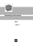
Horn
> 8492/111
Betriebsanleitung
Hupe
> 8492/111
Inhaltsverzeichnis
1
Inhaltsverzeichnis
1
2
3
4
5
6
7
8
9
11
12
13
14
2
Inhaltsverzeichnis ..................................................................................................2
Allgemeine Angaben .............................................................................................2
Allgemeine Sicherheitshinweise ............................................................................3
Vorgesehener Einsatzbereich ...............................................................................4
Technische Daten .................................................................................................5
Transport und Lagerung ........................................................................................6
Funktionsbeschreibung .........................................................................................6
Montage ................................................................................................................7
Installation .............................................................................................................7
Inbetriebnahme ...................................................................................................10
Wartung ...............................................................................................................12
Baumuster-Prüfbescheinigung ............................................................................13
Konformitätserklärung ........................................................................................16
Allgemeine Angaben
2.1 Hersteller
R. STAHL Schaltgeräte GmbH
Am Bahnhof 30
D-74638 Waldenburg
Telefon:
Telefax:
Internet:
+49 7942 943-0
+49 7942 943-4333
www.stahl.de
2.2 Angaben zur Betriebsanleitung
ID-NR.:
Publikations-Nummer:
8492601300
S-BA-8492-00-de-01/2006
Technische Änderungen vorbehalten.
2
Hupe 8492/111
ID-NR.: 8492601300
S-BA-8492-00-de-01/2006
Allgemeine Sicherheitshinweise
3
Allgemeine Sicherheitshinweise
3.1 Sicherheitshinweise für Montage- und Bedienpersonal
Die Betriebsanleitung enthält grundlegende Sicherheitshinweise, die bei Aufstellung, Betrieb und Wartung zu beachten sind. Nichtbeachtung hat eine Gefährdung für Personen,
Anlage und Umwelt zur Folge.
WARNUNG
Gefahr durch unbefugte Arbeiten am Gerät!
Verletzungen und Sachschäden drohen.
Montage, Installation, Inbetriebnahme, Betrieb und Wartung dürfen ausschließlich
von dazu befugtem und entsprechend geschultem Personal durchgeführt werden.
Vor Montage/Inbetriebnahme:
Betriebsanleitung lesen.
Montage- und Betriebspersonal ausreichend schulen.
Sicherstellen, dass der Inhalt der Betriebsanleitung vom zuständigen Personal voll
verstanden wird.
Es gelten die nationalen Montage- und Errichtungsvorschriften (z.B. EN 60079-14).
Bei Betrieb der Geräte:
Betriebsanleitung am Einsatzort verfügbar halten.
Sicherheitshinweise beachten.
Nationale Sicherheits- und Unfallverhütungsvorschriften beachten.
Gerät nur entsprechend der Leistungsdaten betreiben.
Bei Zusammenschaltung mehrerer aktiver Betriebsmittel in einem eigensicheren
Stromkreis können sich andere sicherheitstechnische Werte ergeben, durch die die
Eigensicherheit gefährdet wird.
Wartungsarbeiten bzw. Reparaturen, die nicht in der Betriebsanleitung beschrieben
sind dürfen nicht ohne vorherige Abstimmung mit dem Hersteller durchgeführt werden.
Beschädigungen können den Explosionsschutz aufheben.
Umbauten und Veränderungen am Gerät, die den Explosionsschutz beeinträchtigen,
sind nicht gestattet.
Gerät nur in unbeschädigtem, trockenem und sauberem Zustand einbauen und
betreiben.
Bei Unklarheiten:
Mit Hersteller Kontakt aufnehmen.
3.2 Warnhinweise
Warnhinweise sind in dieser Betriebsanleitung nach folgendem Schema gegliedert:
WARNUNG
Art und Quelle der Gefahr!
Mögliche Folgen.
Maßnahmen zur Vermeidung der Gefahr.
Sie sind dabei immer mit dem Signalwort „WARNUNG“ und teilweise mit einem gefahrenspezifischen Symbol gekennzeichnet.
ID-NR.: 8492601300
S-BA-8492-00-de-01/2006
Hupe 8492/111
3
Vorgesehener Einsatzbereich
3.3 Verwendete Symbole
X
Handlungsaufforderung;
beschreibt durch den Anwender auszuführende Tätigkeiten.
Reaktionszeichen;
beschreibt Resultate bzw. Reaktionen auf Tätigkeiten.
Aufzählung
Beschreibt Hinweise und Empfehlungen.
Gefahr durch spannungsführende Teile!
4
Vorgesehener Einsatzbereich
Die Hupe 8492 ist für den Einsatz als Warnsignalgeber in gasexplosionsgefährdeten
Bereichen vorgesehen.
Die Geräte können in Zone 0, 1, 2 mit den Explosionsgruppen IIA, IIB, IIC und den
Temperaturklassen T1, T2, T3, T4 eingesetzt werden.
Bei Versorgung über zugehörige Betriebsmittel wie Sicherheitsbarrieren oder
galvanische Trennstufen kann die Hupe in den Zonen 0, 1 und 2 betrieben werden.
Die Geräte sind zugelassen für den Umgebungstemperaturbereich von
- 40 °C bis + 60 °C und dürfen außerhalb dieses Bereiches nicht betrieben werden.
Die Geräte sind keine Sicherheitsvorrichtungen im Sinne der Richtlinie 94/9/EG Anhang
II, Absatz 1.5.
Die Installation der Geräte soll von geeignet geschultem Personal gemäß den national
gültigen Errichtungs- und Installationsvorschriften durchgeführt werden.
Die EG-Baumusterprüfbescheinigung basiert auf dem folgenden bei der Konstruktion
verwendeten Material:
X Gehäuse: ABS Kunststoff
X Sollten die Geräte in Kontakt mit aggressiven Medien kommen, liegt es in der
Verantwortung des Betreibers wirksame Maßnahmen zu ergreifen, so dass der
Explosionsschutz und die Funktion der Geräte davon nicht negativ beeinflusst werden.
X "Aggressive Medien" - z.B. Säuren oder Gase welche Metalle angreifen können, oder
Lösungsmittel welche Kunststoffe angreifen können.
X "Wirksame Maßnahmen" - z.B. regelmäßige Inspektionen oder Verwendung von
Bestädigkeitstabellen.
4
Hupe 8492/111
ID-NR.: 8492601300
S-BA-8492-00-de-01/2006
Technische Daten
5
Technische Daten
Explosionsschutz
E II 1 G EEx ia IIC, T4*
* T4 at + 60 °C
Bescheinigungen
SIRA 05 ATEX 2270X**
Lautstärke
105 dB(A), im Abstand von 1 m;
einstellbar
Bemessungsbetriebsspannung Ue
10 V ... 28 V
Bemessungsbetriebsstrom Ie
25 mA
typisch, bei Versorgung mit 24 V über eine Sicherheitsbarriere 28 V,
300 Ω
Elektromagnetische Verträglichkeit
gem. 89/336/EEC
Sicherrheitstechnische Daten
Ui: 28 V
Ii: 93 mA
Pi: 660 mW
Ci: 0
Li: 0
Installation
zu betreiben über jede bescheinigte Sicherheitsbarriere oder galvanische Trennstufe, deren Ausgangsparameter folgende Werte nicht
übersteigen:
U0
I0
P0
28 V, DC
93 mA, DC
660 mW
Gehäusematerial
Kunststoff: ABS
Umgebungsbedingungen
- 40 °C ... + 60 °C
Kabeleinführung
M 20 x 1,5
Anschlussart
Anschlussklemmen für 0,5 mm² ... 2,5 mm²
** BESONDERE BEDINGUNGEN
(gemäß EG-Baumusterprüfbescheinigung SIRA 05ATEX2270X)
X Die Stromversorgung des Geräts erfolgt an den Klemmen + und - über eine
Sicherheitsbarriere oder galvanische Trennstufe mit einer Leerlaufspannung
Uo < 28 V, einem Kurzschlussstrom Io < 93 mA und einer ohmschen Strombegrenzung. Die Barriere oder Trennstufe muss eine EG-Baumusterprüfbescheinigung gemäß Richtlinie 94/9/EG (ATEX) haben.
X Die Geräte sollen nicht in Anlagen installiert werden in denen die Gehäuse aufgrund
vorbeiziehender nicht-leitender Medien statisch aufgeladen werden können.
X Die Geräte werden ohne Kabelverschraubung ausgeliefert. Daher wird die Schutzart
von IP66 erst durch die korrekte Installation einer geeigneten Kabelverschraubung erreicht. Ohne Kabelverschraubung beträgt die Schutzart mindestens IP20.
X Die maximale zulässige an den Klemmen + und - anschließbare Kapazität (Kabelkapazität plus Kapazität der Trennstufe) soll nicht mehr als 83nF betragen.
ID-NR.: 8492601300
S-BA-8492-00-de-01/2006
Hupe 8492/111
5
Transport und Lagerung
Maßzeichnungen
Typenschild
6
Transport und Lagerung
Transport
Erschütterungsfrei in Originalkarton, nicht stürzen, vorsichtig handhaben.
Lagerung
Trocken in Originalverpackung lagern
7
Funktionsbeschreibung
Die Hupen 8492/111 sind für den Einsatz als Warnsignalgeber in explosionsgefährdeten
Bereichen vorgesehen.
Sie verfügen über 49 verschiedene Signalfolgen, die über innenliegende DIP-Schalter
gewählt werden können. Über eine äußere Beschaltung sind drei verschiedene Signalfolgen je DIP-Schalterstellung abrufbar.
Es können mehrere Hupen parallel betrieben werden. Die Tonfolgen-Synchronisation erfolgt über einen internen quarzgesteuerten Oszillator.
Die Lautstärke ist stufenlos regelbar.
Die EG-Baumusterprüfbescheinigung erlaubt den Parallelbetrieb von bis zu drei Hupen
mit einer Barriere oder Trennstufe. Bei Anschluss zweier parallel geschalteter Hupen reduziert sich die Schallleistung um 3dB. Drei Hupen dürfen nur dann mit einer gemeinsamen Versorgung angeschlossen werden, wenn die volle Versorgungsspannung zur
Verfügung steht.
6
Hupe 8492/111
ID-NR.: 8492601300
S-BA-8492-00-de-01/2006
Montage
8
Montage
Hupe mit zwei Schrauben (nicht im Lieferumfang enthalten) an der Wand befestigen;
gegebenenfalls Dübel benutzen.
Hupe so befestigen, dass sie nicht als Steighilfe benutzt werden kann!
Montage der Kabeleinführungen
Front, Hupelement und Elektronik sind mit einem Plastikband am Hupengehäuse befestigt.
Kreuzschlitzschrauben lösen und herausdrehen. Unterlegscheiben nicht verlieren.
Front mit Hupelement und Elektronik herausnehmen.
Kabeleinführung M 20 x 1,5 (nicht im Lieferumfang enthalten) einbauen.
9
Installation
Die Hupen 8492/111 müssen über Sicherheitsbarrieren oder galvanische Trennstufen
betrieben werden, deren Ausgangsparameter folgende Werte nicht übersteigen:
U0: 28 V, DC
I0: 93 mA, DC
P0: 660 mW
Kabelparameter
WARNUNG
Die maximal erlaubten Kabelparameter müssen den sicherheitstechnischen Werten
der EG-Baumusterprüfbescheiningung der angeschlossenen Sicherheitsbarriere
bzw. galvanischen Trennstufe entsprechen.
ID-NR.: 8492601300
S-BA-8492-00-de-01/2006
Hupe 8492/111
7
Installation
Installation mittels Sicherheitsbarrieren
Schaltung für die 1. Signalfolge mit Schalter im positiven Zweig:
Anschluss über eine einkanalige Sicherheitsbarriere
(z.B. STAHL-Typ 9001/01-280-085-101)
Wird ein Schalter im positiven Zweig verwendet, bzw. wird die Stromversorgung ein- und
ausgeschaltet, so genügt eine einkanalige Sicherheitsbarriere.
Schaltung für die 1. Signalfolge mit Schalter im negativen Zweig:
Anschluss über eine zweikanalige Sicherheitsbarriere
(z.B. STAHL-Typ 9002/13-280-093-001)
Wird der Schalter im negativen Zweig verwendet (z.B. SPS), dann muss eine zweikanalige Auswertbarriere mit Dioden im Rückzweig verwendet werden.
8
Hupe 8492/111
ID-NR.: 8492601300
S-BA-8492-00-de-01/2006
Installation
Schaltung für die 2. und 3. Signalfolge:
Schaltung für die 2. und 3. Signalfolge
(z.B. STAHL-Typen 9002/13-280-093-001 und 9002/33-280-000-001)
Schaltet man die Klemme S2 der Hupe über die Barriereklemmen 3 und 1 auf die Versorgungsspannung (0 V), dann wird die 2. Signalfolge aktiviert.
Analog dazu: Schaltet man die Klemme S3 der Hupe über die Barriereklemmen 4 und 2
auf die Versorgunsspannung (0 V), dann wird die 3. Signalfolge aktiviert.
ID-NR.: 8492601300
S-BA-8492-00-de-01/2006
Hupe 8492/111
9
Inbetriebnahme
10 Inbetriebnahme
Ansicht der Bedienelemente
10.1 Anklemmen der Leitungen
Kabel durch Kabeleinführung einführen.
Leitungen ca. 3 mm mit geeignetem Werkzeug abisolieren.
Leitungen je nach Schaltung (s. Kapitel 9 „Installation“) in Klemmen (1) einführen und
befestigen.
Kabeleinführung zudrehen.
Die Klemmenblöcke „+“ und „-“ sind doppelt vorhanden.
10.2 Wahl der Tonfolge
Mit einem kleinen Schraubendreher die DIP-Schalter (2) 1-6 anordnen. Tonbeschreibung siehe Kapitel 10.4 „Tonkombinationen für Hupen“.
DIP-Schalter „oben“ entspricht „1“
DIP-Schalter „unten“ entspricht „0“
10.3 Einstellen der Lautstärke
Mit einem kleinen Schraubendreher den Lautstärkenregler (3) betätigen.
Drehen im Uhrzeigersinn erhöht die Lautstärke.
10
Hupe 8492/111
ID-NR.: 8492601300
S-BA-8492-00-de-01/2006
Inbetriebnahme
10.4 Mögliche Tonkombinationen für Hupen
DIP-Schalter
Ton
number
Frequenz
Ton 1
Ton 2
Ton 3
340 Hz
800/1000 Hz
500/1200 Hz
Ton 4
Ton 5
Ton 6
Ton 7
Ton 8
Ton 9
Ton 10
Ton 11
Ton 12
Ton 13
Ton 14
Ton 15
Ton 16
500/1000 Hz
2400 Hz
2400/2900 Hz
2400/2900 Hz
500/1200/500 Hz
1200/500 Hz
2400/2900 Hz
1000 Hz
800/1000 Hz
2400 Hz
800 Hz
800 Hz
660 Hz
Ton 17
544/440 Hz
Ton 18
660 Hz
Ton 19
Ton 20
Ton 21
Ton 22
Ton 23
Ton 24
Ton 25
Ton 26
Ton 27
Ton 28
Ton 29
Ton 30
Ton 31
Ton 32
Ton 33
Ton 34
Ton 35
Ton 36
Ton 37
Ton 38
Ton 39
Ton 40
von 1400 Hz bis 1600 Hz
von 1600 Hz bis 1400 Hz
660 Hz
554/440 Hz
544 Hz
800 Hz
800/1000 Hz
2400/2900 Hz
Glocke (simuliert)
554 Hz
440 Hz
800/1000 Hz
300 Hz
660/1200 Hz
2-Ton-Glocke (simuliert)
745 Hz
1000/2000 Hz
420 Hz
von 500 Hz bis 1000 Hz
1000 Hz
2000 Hz
800 Hz
544/440 Hz
Ton 41
Ton 42
Ton 43
Ton 44
Ton 45
Ton 46
Sirene
Sirene
1200 Hz
Sirene
1000 Hz
1200/500 Hz
Ton 47
1000 Hz
Ton 48
Ton 49
420 Hz
von 500 bis 1200 Hz
ID-NR.: 8492601300
S-BA-8492-00-de-01/2006
Intervall
Dauerton
Wechselton mit 0,25 s Intervallen
„Slow Whoop“ mit 0,3 Hz mit 0,5 s
Pause
Wischton mit 1 Hz
Dauerton
Wischton mit 7 Hz
Wischton mit 1 Hz
Sirene mit 0.3 Hz
„Sägezahnton“ mit 1 Hz - DIN
Wechselton mit 2 Hz
unterbrochener Ton mit 1 kHz
Wechselton mit 0,875 Hz
unterbrochener Ton mit 1 Hz
unterbrochener Ton 0,25 s an; 1 s aus
Dauerton
unterbrochener Ton
0,15 s an; 0,15 s aus
Wechselton 100 ms/400 ms NFS 32-001
unterbrochener Ton
1,8 s an; 1,8 s aus
in 1 s;
in 0,5 s
Dauerton
Wechselton mit 1 Hz
unterbrochener Ton mit 0,875 Hz
unterbrochener Ton mit 2 Hz
Wischton mit 50 Hz
Wischton mit 50 Hz
Zweite
Ton1 2 3 4 5 6 folge
Dritte
Tonfolge
0 0 0 0 0 0 Ton 2
1 0 0 0 0 0 Ton 17
0 1 0 0 0 0 Ton 2
Ton 5
Ton 5
Ton 5
1
0
1
0
1
0
1
0
1
0
1
0
1
Ton 6
Ton 3
Ton 7
Ton 10
Ton 2
Ton 15
Ton 7
Ton 2
Ton 4
Ton 15
Ton 4
Ton 2
Ton 18
Ton 5
Ton 20
Ton 5
Ton 5
Ton 5
Ton 2
Ton 5
Ton 5
Ton 5
Ton 5
Ton 5
Ton 5
Ton 5
1
0
0
1
1
0
0
1
1
0
0
1
1
0
1
1
1
1
0
0
0
0
1
1
1
1
0
0
0
0
0
1
1
1
1
1
1
1
1
0
0
0
0
0
0
0
0
0
0
0
0
0
0
0
0
0
0
0
0
0
0
0
0
0
0
0 0
0 0
1 0
Ton 2
Ton 27
1 0
0 0
1 0
Ton 2
Ton 5
0 1
0 0
1 0
Ton 2
Ton 5
1
0
0
1
1
0
0
1
1
0
0
1
1
0
0
1
1
0
0
1
1
0
1
1
1
1
0
0
0
0
1
1
1
1
0
0
0
0
1
1
1
1
0
0
0
0
0
1
1
1
1
1
1
1
1
0
0
0
0
0
0
0
0
1
1
1
1
1
1
1
1
1
1
1
1
1
0
0
0
0
0
0
0
0
0
0
0
0
0
0
0
0
0
0
0
0
0
1
1
1
1
1
1
1
1
Ton 2
Ton 2
Ton 2
Ton 6
Ton 29
Ton 29
Ton 2
Ton 26
Ton 2
Ton 7
Ton 2
Ton 26
Ton 26
Ton 2
Ton 38
Ton 36
Ton 35
Ton 9
Ton 34
Ton 23
Ton 31
Ton 5
Ton 5
Ton 5
Ton 5
Ton 5
Ton 5
Ton 15
Ton 5
Ton 5
Ton 5
Ton 5
Ton 5
Ton 15
Ton 5
Ton 45
Ton 5
Ton 5
Ton 45
Ton 45
Ton 17
Ton 27
0
0
1
1
0
0
0
0
0
0
1
1
1
1
1
1
1
1
0
0
0
0
0
0
1
1
1
1
1
1
Ton 2
Ton 2
Ton 2
Ton 2
Ton 38
Ton 47
Ton 5
Ton 5
Ton 5
Ton 5
Ton 34
Ton 37
1
1 1
0 1
Ton 46
Ton 37
1 1 1 0 1 Ton 49
0 0 0 1 1 Ton 26
Ton 5
Ton 37
1
0
1
0
1
0
1
Dauerton
0
Dauerton
1
Wischton mit 7 Hz
0
Dauerton
1
Wischton mit 1 Hz
0
1
unterbrochener Ton
0
Wechselton mit 0,5 s - „Singapore“
1
mit 0,625 s - „Australian alert“
0
3,75 s/0,25 s - „Australian evac.“
1
Dauerton
0
Dauerton
1
unterbrochener Ton 0,25 s an; 1 s aus 0
Wechselton 100 ms/400 ms 1
NFS 32-001
langsam ansteigend bis 1200 Hz
0
langsam ansteigend bis 800 Hz
1
Dauerton
0
langsam ansteigend bis 2400 Hz
1
unterbrochener Ton 1 s an; 1 s aus 0
„Sägezahnton“ mit 1 Hz - DIN /
1
PFEER „Prepare to abandon platform“
unterbrochener Ton 1 s an; 1 s aus - 0
„PFEER General Alarm“
mit 0,625 s - „Australian Alert“
1
3,75 s /0,25 s - „Australian evacuate“ 0
Hupe 8492/111
11
Wartung
11 Wartung
WARNUNG
Wartungs- und Instandsetzungsarbeiten nur durch Fachpersonal!
Wartungs- und Instandsetzungsarbeiten an den Geräten dürfen nur von dazu befugtem und entsprechend geschultem Personal durchgeführt werden.
Geltende nationale Bestimmungen im Einsatzland beachten.
Im Rahmen der Wartung Prüfen:
Leitungen auf festen Sitz.
Gehäuse auf sichtbare Schäden.
Einhaltung der zulässigen Temperaturen gem. EN 50014.
Bestimmungsgemäße Funktion.
Regelmäßig die Hupe auf ordnungsgemäßen Zustand hinsichtlich der Montage, der
Installation und des Betriebes Prüfen.
Art und Umfang der Prüfungen den entsprechenden Vorschriften (z.B. IEC/EN/DIN
60079-17) entnehmen. Die Fristen so bemessen, dass entstehende Mängel in der Anlage, mit denen zu rechnen ist, rechtzeitig festgestellt werden.
12
Hupe 8492/111
ID-NR.: 8492601300
S-BA-8492-00-de-01/2006
Baumuster-Prüfbescheinigung
12 Baumuster-Prüfbescheinigung
ID-NR.: 8492601300
S-BA-8492-00-de-01/2006
Hupe 8492/111
13
Baumuster-Prüfbescheinigung
14
Hupe 8492/111
ID-NR.: 8492601300
S-BA-8492-00-de-01/2006
Baumuster-Prüfbescheinigung
ID-NR.: 8492601300
S-BA-8492-00-de-01/2006
Hupe 8492/111
15
Konformitätserklärung
13 Konformitätserklärung
16
Hupe 8492/111
ID-NR.: 8492601300
S-BA-8492-00-de-01/2006
Operating Instructions
Horn
> 8492/111
Table of Contents
1
Table of Contents
1
2
3
4
5
6
7
8
9
10
11
12
13
2
Table of Contents ..................................................................................................2
General information ...............................................................................................2
General safety instructions ....................................................................................3
Intended field of application ...................................................................................4
Technical data .......................................................................................................5
Transportation and storage ...................................................................................6
Functional description ...........................................................................................6
Assembly ...............................................................................................................7
Installation .............................................................................................................7
Commissioning ....................................................................................................10
Maintenance ........................................................................................................12
Type Examination Certificate ..............................................................................13
Declaration of Conformity ....................................................................................16
General information
2.1 Manufacturer
R. STAHL Schaltgeräte GmbH
Am Bahnhof 30
D-74638 Waldenburg, Germany.
Telephone:
Fax:
Internet:
+49 7942 943-0
+49 7942 943-4333
www.stahl.de
2.2 Information about the operating instructions
ID-NO.:
Publication Number:
8492601300
S-BA-8492-00-en-01/2006
We reserve the right to make technical changes without notice.
2
Horn 8492/111
ID-NR.: 8492601300
S-BA-8492-00-en-01/2006
General safety instructions
3
General safety instructions
3.1 Safety instructions for installation and operating personnel
The operating instructions contain basic safety instructions to be followed during installation, operation and maintenance. Not following the instruction can be hazardous to personnel, equipment and the environment.
WARNING!
Unauthorised use of the device is hazardous!
Injuries and damage may be the result.
Connection, installation, commissioning, operation and maintenance may only be
performed by authorised personnel suitably trained for this purpose.
Before connection/operation:
Read the operating instructions.
Properly train the installation and operating personnel.
Ensure that the contents of the operating instructions are fully understood by the relevant personnel.
The national installation and assembly regulations apply.
(e.g. EN 60079-14):
When operating the devices:
Ensure that the operating instructions are available where the device is used.
Follow the safety instructions.
Follow national safety and accident prevention regulations.
Only operate the devices in accordance with their performance data.
Interconnecting several active devices in an intrinsically safe circuit may result in other
safety values which jeopardise intrinsically safety.
Maintenance and repair work not described in the operating instructions may not be
performed without prior approval from the manufacturer.
Damage can compromise and even neutralise the explosion protection.
Modifications and alterations to the device that impair its explosion protection are not
permitted.
Devices may only be installed and operated when undamaged, dry and clean.
If you have questions:
Contact the manufacturer.
3.2 Warnings
Warnings are indicated in these operating instructions using the following format:
WARNING!
Source and type of hazard!
Possible consequences.
Action to take to prevent the hazard.
Warnings are always indicated by the signal word "WARNING" and may also be indicated
by the hazard symbol.
ID-NR.: 8492601300
S-BA-8492-00-en-01/2006
Horn 8492/111
3
Intended field of application
3.3 Symbols used
X
Prompt for action;
describes the tasks to be performed by the user.
Reaction symbol;
describes the results of or reactions to actions.
List
Describes instructions and recommendations.
Danger, energised parts!
4
Intended field of application
The horn 8492 is intended for use as a warning device in explosive gas atmospheres.
The equipment may be used in zones 0, 1 and 2 with flammable gases and vapours with
apparatus groups IIA, IIB & IIC and with temperature classes T1, T2, T3 and T4.
The horn may be operated in Zones 0, 1 and 2 if it is powered via related equipment such
as safety barriers or galvanic isolator.
The equipment is only certified for use in ambient temperatures in the range
- 40°C to + 60°C and should not be used outside this range.
The equipment has not been assessed as a safety-related device (as referred to by Directive 94/9/EC Annex II, clause 1.5).
Installation of this equipment shall be carried out by suitably-trained personnel in accordance with the applicable code of practice. Repair of this equipment shall only be carried
out by the manufacturer or in accordance with the applicable code of practice.
The certification of this equipment relies on the following materials used in its construction:
X Enclosure: ABS Plastic
X If the equipment is likely to come into contact with aggressive substances, then it is the
responsibility of the user to take suitable precautions that prevent it from being adversely affected, thus ensuring that the type of protection is not compromised.
X "Aggressive substances" - e.g. acidic liquids or gases that may attack metals, or solvents that may affect polymeric materials.
X "Suitable precautions" - e.g. regular checks as part of routine inspections or establishing from the material's data sheet that it is resistant to specific chemicals.
4
Horn 8492/111
ID-NR.: 8492601300
S-BA-8492-00-en-01/2006
Technical data
5
Technical data
Explosion protection
E II 1 G EEx ia IIC, T4*
* T4 at + 60 °C
Certifications
SIRA 05 ATEX 2270X**
Volume
105 dB(A) at a distance of 1 m;
adjustable
Rated operating voltage Uin
10 V ... 28 V
Rated operating current Iin
25 mA
typical value, in the case of 24 V power supply via a 28 V safety barrier,
300 Ω
Electromagnetic compatibility
in accordance with 89/336/EEC
Safety values
Ui: 28 V
Ii: 93 mA
Pi: 660 mW
Ci: 0
Li: 0
Installation
Can be operated via any certified safety barrier or galvanic isolator
whose output parameters do not exceed the following values:
U0
I0
P0
28 V DC
93 mA, DC
660 mW
Housing material
Plastic: ABS
Ambient conditions
- 40 °C ... + 60 °C
Cable entry point
M 20 x 1.5
Type of connection
Connection terminals for 0.5 mm² ... 2.5 mm²
** SPECIAL CONDITIONS FOR SAFE USE
(as stated on the EC Type Examination Certificate SIRA 05ATEX2270X)
X The equipment shall only be supplied via Terminals + w.r.t. Terminals - from a barrier
having a maximum open circuit voltage Uo that is < 28 V and a maximum short circuit
current Io that is < 93 mA, where Io is resistively limited. The barrier shall be ATEX certified by a notified body.
X The equipment shall not be directly installed in any process where its enclosure might
be statically charged by the rapid flow of a non-conductive media.
X The equipment has an ingress protection rating of IP66; however, if it has been supplied without a cable entry device, then the user shall ensure that the device that is fitted
will provide an ingress protection that is appropriate to the environment in which it is
installed i.e. IP20 or better.
X The total capacitance connected to terminals + wrt - (i.e. the capacitance of the cable
plus any other capacitance) shall not exceed 83nF.
ID-NR.: 8492601300
S-BA-8492-00-en-01/2006
Horn 8492/111
5
Transportation and storage
Dimension drawings
Typelabel
6
Transportation and storage
Transport
X Free of vibration in original carton, do not drop, handle carefully.
Storage
X Store dry in original packaging
7
Functional description
The horns 8492/111 are intended for use as warning devices in hazardous areas.
They feature 49 different signal sequences which can be selected by internal DIP switches. Three different signal sequences per DIP switch setting can be selected by means
of an external circuit.
Several horns can be operated in parallel. The tone sequences are synchronised by means of an internal, crystal-controlled oscillator.
The volume can be adjusted steplessly.
The EC Type Examination Certificate allows parallel operation of up to three horns with
a barrier or isolator. In the case of connection of two parallel-connected horns, the sound
power output is reduced by 3 dB. Three horns may be connected to a common power
supply only if the full supply voltage is available.
6
Horn 8492/111
ID-NR.: 8492601300
S-BA-8492-00-en-01/2006
Assembly
8
Assembly
Attach the horn to the wall with two screws (not included in the scope of delivery); use
dowels if necessary.
Attach the horn so that it cannot be used as a climbing aid!
Installation of the cable entries
Front-panel, horn element and electronic are attached to the horn housing
with a plastic strip.
Undo the cross-head screws and unscrew them. Do not lose the washers.
Remove the front panel with horn element and electronic.
Insert the cable entry M 20 x 1.5 (not included in the scope of delivery).
9
Installation
The horns 8492/111 must be operated via safety barriers or galvanic isolators whose output parameters do not exceed the following values:
U0: 28 V, DC
I0: 93 mA, DC
P0: 660 mW
Cable parameters
WARNING
The maximum permitted cable parameters are as specified on the certificate of the
Zener barrier or galvanic isolator that has been selected for the installation.
ID-NR.: 8492601300
S-BA-8492-00-en-01/2006
Horn 8492/111
7
Installation
Installation with safety barriers
Circuit for the 1st signal sequence with switch in the positive line:
Connection via a single-channel safety barrier
(e.g. STAHL Type 9001/01-280-085-101)
If a switch is used in the positive line or if the power supply is switched ON and OFF, a
single-channel safety barrier will suffice.
Circuit for the 1st signal sequence with switch in the negative line:
Connection via a two-channel safety barrier
(e.g. STAHL Type 9002/13-280-093-001)
If the switch in the negative line is used (e.g. PLC), a two-channel evaluation barrier with
diodes in the return branch must be used.
8
Horn 8492/111
ID-NR.: 8492601300
S-BA-8492-00-en-01/2006
Installation
Circuit for the 2nd and 3rd signal sequences
Circuit for the 2nd and 3rd signal sequences
(e.g. STAHL Types 9002/13-280-093-001 and 9002/33-280-000-001)
If terminal S2 of the horn is connected to the supply voltage (0 V) via the barrier terminals
3 and 1, the second signal sequence is activated.
Analogously, if terminal S3 of the horn is connected to the supply voltage (0 V) via the
barrier terminals 4 and 2, the 3rd signal sequence is activated.
ID-NR.: 8492601300
S-BA-8492-00-en-01/2006
Horn 8492/111
9
Commissioning
10 Commissioning
View of the operating controls
10.1 Cable terminal connections
Insert the cable through the cable entry.
Strip the insulation from the cables to a length of approx. 3 mm with a suitable tool.
Insert the cables into the terminals (1), depending on circuit (see Chapter 9 "Installation") and secure them.
Screw the cable entry tight.
The terminal blocks "+" and "-" are provided twice.
10.2 Selection of the tone sequence
Using a small screwdriver, arrange the settings of the DIP switches (2) 1-6. See Chapter 10.4 "Tone combination for horns" for a description of the tones.
DIP switch "up" corresponds to "1"
DIP switch "down" corresponds to "0"
10.3 Setting the volume
Use a small screwdriver to operate the volume control (3).
Turning clockwise increases the volume.
10
Horn 8492/111
ID-NR.: 8492601300
S-BA-8492-00-en-01/2006
Commissioning
10.4 Possible tone combinations for horns
Tone
number
DIP switches
Frequency
Tone 1
Tone 2
Tone 3
340 Hz
800/1000 Hz
500/1200 Hz
Tone 4
Tone 5
Tone 6
Tone 7
Tone 8
Tone 9
Tone 10
Tone 11
Tone 12
Tone 13
Tone 14
Tone 15
Tone 16
Tone 17
500/1000 Hz
2400 Hz
2400/2900 Hz
2400/2900 Hz
500/1200/500 Hz
1200/500 Hz
2400/2900 Hz
1000 Hz
800/1000 Hz
2400 Hz
800 Hz
800 Hz
660 Hz
544/440 Hz
Tone 18 660 Hz
Tone 19 from1400 Hz to 1600 Hz
from 1600 Hz to 1400 Hz
Tone 20 660 Hz
Tone 21 554/440 Hz
Tone 22 544 Hz
Tone 23 800 Hz
Tone 24 800/1000 Hz
Tone 25 2400/2900 Hz
Tone 26 Simulated Bell
Tone 27 554 Hz
Tone 28 440 Hz
Tone 29 800/1000 Hz
Tone 30 300 Hz
Tone 31 660/1200 Hz
Tone 32 Two tone chime
Tone 33 745 Hz
Tone 34 1000/2000 Hz
Tone 35 420 Hz
Tone 36 from 500 Hz to 1000 Hz
Tone 37 1000 Hz
Tone 38 2000 Hz
Tone 39 800 Hz
Tone 40 544/440 Hz
Tone 41
Tone 42
Tone 43
Tone 44
Tone 45
Tone 46
Motor Siren
Motor Siren
1200 Hz
Motor Siren
1000 Hz
1200/500 Hz
Tone 47 1000 Hz
Tone 48 420 Hz
Tone 49 from 500 to 1200 Hz
ID-NR.: 8492601300
S-BA-8492-00-en-01/2006
Interval
Continuous
Alternating at 0.25 s intervalls
Slow Whoop at 0.3 Hz with 0.5 s
gap repeated
Sweeping at 1 Hz
Continuous
Sweeping at 7 Hz
Sweeping at 1 Hz
Siren at 0.3 Hz
Saw Tooth at 1 Hz - DIN
Alternating at 2 Hz
Intermittent at 1 kHz
Alternating at 0.875 Hz
Intermittent at 1 Hz
Intermittent 0.25 s on; 1 s off
Continuous
Intermittent 0.15 s on; 0.15 s off
Alternating 100 ms/400 ms NFS 32-001
Intermittent 1.8 s on; 1.8 s off
in 1 s;
in 0.5 s
Continuous
Alternating at 1 Hz
Intermittent at 0.875 Hz
Intermittent at 2 Hz
Sweeping at 50 Hz
Sweeping at 50 Hz
Continuous
Continuous
Sweeping at 7 Hz
Continuous
Sweeping at 1 Hz
Intermittent
Alternating at 0.5 s - Singapore
at 0.625 s - Australian alert
3.75 s/0.25 s - Australian evac.
Continuous
Continuous
Intermittent 0.25 s on; 1 s off
Alternating 100 ms/400 ms NFS 32-001
Slow Rise to 1200 Hz
Slow Rise to 800 Hz
Continuous
Slow Rise to 2400 Hz
Intermittent 1 s on; 1 s off
Saw Tooth at 1 Hz - DIN / PFEER
„Prepare to abandon platform“
Intermittent 1 s on; 1 s off PFEER General Alarm
at 0.625 s - Australian Alert
3.75 s /0.25 s - Australian evacuate
1 2 3 4 5 6
Second
tone
Third
tone
0 0 0 0 0 0 Tone 2
1 0 0 0 0 0 Tone 17
0 1 0 0 0 0 Tone 2
Tone 5
Tone 5
Tone 5
1
0
1
0
1
0
1
0
1
0
1
0
1
0
Tone 5
Tone 20
Tone 5
Tone 5
Tone 5
Tone 2
Tone 5
Tone 5
Tone 5
Tone 5
Tone 5
Tone 5
Tone 5
Tone 27
1
0
0
1
1
0
0
1
1
0
0
1
1
0
0
1
1
1
1
0
0
0
0
1
1
1
1
0
0
0
0
0
0
1
1
1
1
1
1
1
1
0
0
0
0
0
0
0
0
0
0
0
0
0
0
1
0
0
0
0
0
0
0
0
0
0
0
0
0
0
Tone 6
Tone 3
Tone 7
Tone 10
Tone 2
Tone 15
Tone 7
Tone 2
Tone 4
Tone 15
Tone 4
Tone 2
Tone 18
Tone 2
1 0 0 0 1 0 Tone 2
0 1 0 0 1 0 Tone 2
Tone 5
Tone 5
1
0
1
0
1
0
1
0
1
0
1
0
1
0
1
0
1
0
1
0
1
1
0
0
1
1
0
0
1
1
0
0
1
1
0
0
1
1
0
0
1
1
0
1
1
1
1
0
0
0
0
1
1
1
1
0
0
0
0
1
1
1
1
0
0
0
0
0
1
1
1
1
1
1
1
1
0
0
0
0
0
0
0
0
1
1
1
1
1
1
1
1
1
1
1
1
1
0
0
0
0
0
0
0
0
0
0
0
0
0
0
0
0
0
0
0
0
0
1
1
1
1
1
1
1
1
Tone 2
Tone 2
Tone 2
Tone 6
Tone 29
Tone 29
Tone 2
Tone 26
Tone 2
Tone 7
Tone 2
Tone 26
Tone 26
Tone 2
Tone 38
Tone 36
Tone 35
Tone 9
Tone 34
Tone 23
Tone 31
Tone 5
Tone 5
Tone 5
Tone 5
Tone 5
Tone 5
Tone 15
Tone 5
Tone 5
Tone 5
Tone 5
Tone 5
Tone 15
Tone 5
Tone 45
Tone 5
Tone 5
Tone 45
Tone 45
Tone 17
Tone 27
0
1
0
1
0
1
0
0
1
1
0
0
0
0
0
0
1
1
1
1
1
1
1
1
0
0
0
0
0
0
1
1
1
1
1
1
Tone 2
Tone 2
Tone 2
Tone 2
Tone 38
Tone 47
Tone 5
Tone 5
Tone 5
Tone 5
Tone 34
Tone 37
1 Tone 46
Tone 37
1 1 1 1 0 1 Tone 49
0 0 0 0 1 1 Tone 26
Tone 5
Tone 37
0 1 1
1 0
Horn 8492/111
11
Maintenance
11 Maintenance
WARNING
Maintenance and repair work may be carried out only by specialist personnel!
Maintenance and repair work on the devices may be carried out only by authorised, appropriately trained personnel.
Observe applicable national regulations in the country of use.
Check the following within the framework of maintenance:
Cables for firm attachment.
Housing for visible damage.
Compliance with the permitted temperatures in accordance with EN 50014.
Function as intended.
Regularly inspect the horn in order to ensure that it is in proper conditions in respect
of installation, wiring and operation.
Please refer to the corresponding regulations (e.g. IEC/EN/DIN 60079-17) for the nature
and scope of the tests and inspections. Plan the intervals so that any defects in the equipment which may be anticipated are promptly detected.
12
Horn 8492/111
ID-NR.: 8492601300
S-BA-8492-00-en-01/2006
Type Examination Certificate
12 Type Examination Certificate
ID-NR.: 8492601300
S-BA-8492-00-en-01/2006
Horn 8492/111
13
Type Examination Certificate
14
Horn 8492/111
ID-NR.: 8492601300
S-BA-8492-00-en-01/2006
Type Examination Certificate
ID-NR.: 8492601300
S-BA-8492-00-en-01/2006
Horn 8492/111
15
Declaration of Conformity
13 Declaration of Conformity
16
Horn 8492/111
ID-NR.: 8492601300
S-BA-8492-00-en-01/2006
ID-NR.: 8492601300
S-BA-8492-00-de/en-01/2006
ID-NR.: 8492601300
S-BA-8492-00-de/en-01/2006