1
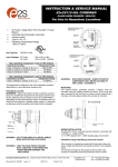
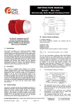
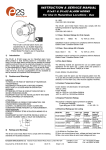
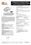
Operating Instructions
Horn
> 8492/111
Table of Contents
1
Table of Contents
1
2
3
4
5
6
7
8
9
10
11
12
13
2
Table of Contents ..................................................................................................2
General information ...............................................................................................2
General safety instructions ....................................................................................3
Intended field of application ...................................................................................4
Technical data .......................................................................................................5
Transportation and storage ...................................................................................6
Functional description ...........................................................................................6
Assembly ...............................................................................................................7
Installation .............................................................................................................7
Commissioning ....................................................................................................10
Maintenance ........................................................................................................12
Type Examination Certificate ..............................................................................13
Declaration of Conformity ....................................................................................16
General information
2.1 Manufacturer
R. STAHL Schaltgeräte GmbH
Am Bahnhof 30
D-74638 Waldenburg, Germany.
Telephone:
Fax:
Internet:
+49 7942 943-0
+49 7942 943-4333
www.stahl.de
2.2 Information about the operating instructions
ID-NO.:
Publication Number:
8492601300
S-BA-8492-00-en-01/2006
We reserve the right to make technical changes without notice.
2
Horn 8492/111
ID-NR.: 8492601300
S-BA-8492-00-en-01/2006
General safety instructions
3
General safety instructions
3.1 Safety instructions for installation and operating personnel
The operating instructions contain basic safety instructions to be followed during installation, operation and maintenance. Not following the instruction can be hazardous to personnel, equipment and the environment.
WARNING!
Unauthorised use of the device is hazardous!
Injuries and damage may be the result.
Connection, installation, commissioning, operation and maintenance may only be
performed by authorised personnel suitably trained for this purpose.
Before connection/operation:
Read the operating instructions.
Properly train the installation and operating personnel.
Ensure that the contents of the operating instructions are fully understood by the relevant personnel.
The national installation and assembly regulations apply.
(e.g. EN 60079-14):
When operating the devices:
Ensure that the operating instructions are available where the device is used.
Follow the safety instructions.
Follow national safety and accident prevention regulations.
Only operate the devices in accordance with their performance data.
Interconnecting several active devices in an intrinsically safe circuit may result in other
safety values which jeopardise intrinsically safety.
Maintenance and repair work not described in the operating instructions may not be
performed without prior approval from the manufacturer.
Damage can compromise and even neutralise the explosion protection.
Modifications and alterations to the device that impair its explosion protection are not
permitted.
Devices may only be installed and operated when undamaged, dry and clean.
If you have questions:
Contact the manufacturer.
3.2 Warnings
Warnings are indicated in these operating instructions using the following format:
WARNING!
Source and type of hazard!
Possible consequences.
Action to take to prevent the hazard.
Warnings are always indicated by the signal word "WARNING" and may also be indicated
by the hazard symbol.
ID-NR.: 8492601300
S-BA-8492-00-en-01/2006
Horn 8492/111
3
Intended field of application
3.3 Symbols used
X
Prompt for action;
describes the tasks to be performed by the user.
Reaction symbol;
describes the results of or reactions to actions.
List
Describes instructions and recommendations.
Danger, energised parts!
4
Intended field of application
The horn 8492 is intended for use as a warning device in explosive gas atmospheres.
The equipment may be used in zones 0, 1 and 2 with flammable gases and vapours with
apparatus groups IIA, IIB & IIC and with temperature classes T1, T2, T3 and T4.
The horn may be operated in Zones 0, 1 and 2 if it is powered via related equipment such
as safety barriers or galvanic isolator.
The equipment is only certified for use in ambient temperatures in the range
- 40°C to + 60°C and should not be used outside this range.
The equipment has not been assessed as a safety-related device (as referred to by Directive 94/9/EC Annex II, clause 1.5).
Installation of this equipment shall be carried out by suitably-trained personnel in accordance with the applicable code of practice. Repair of this equipment shall only be carried
out by the manufacturer or in accordance with the applicable code of practice.
The certification of this equipment relies on the following materials used in its construction:
X Enclosure: ABS Plastic
X If the equipment is likely to come into contact with aggressive substances, then it is the
responsibility of the user to take suitable precautions that prevent it from being adversely affected, thus ensuring that the type of protection is not compromised.
X "Aggressive substances" - e.g. acidic liquids or gases that may attack metals, or solvents that may affect polymeric materials.
X "Suitable precautions" - e.g. regular checks as part of routine inspections or establishing from the material's data sheet that it is resistant to specific chemicals.
4
Horn 8492/111
ID-NR.: 8492601300
S-BA-8492-00-en-01/2006
Technical data
5
Technical data
Explosion protection
E II 1 G EEx ia IIC, T4*
* T4 at + 60 °C
Certifications
SIRA 05 ATEX 2270X**
Volume
105 dB(A) at a distance of 1 m;
adjustable
Rated operating voltage Uin
10 V ... 28 V
Rated operating current Iin
25 mA
typical value, in the case of 24 V power supply via a 28 V safety barrier,
300 Ω
Electromagnetic compatibility
in accordance with 89/336/EEC
Safety values
Ui: 28 V
Ii: 93 mA
Pi: 660 mW
Ci: 0
Li: 0
Installation
Can be operated via any certified safety barrier or galvanic isolator
whose output parameters do not exceed the following values:
U0
I0
P0
28 V DC
93 mA, DC
660 mW
Housing material
Plastic: ABS
Ambient conditions
- 40 °C ... + 60 °C
Cable entry point
M 20 x 1.5
Type of connection
Connection terminals for 0.5 mm² ... 2.5 mm²
** SPECIAL CONDITIONS FOR SAFE USE
(as stated on the EC Type Examination Certificate SIRA 05ATEX2270X)
X The equipment shall only be supplied via Terminals + w.r.t. Terminals - from a barrier
having a maximum open circuit voltage Uo that is < 28 V and a maximum short circuit
current Io that is < 93 mA, where Io is resistively limited. The barrier shall be ATEX certified by a notified body.
X The equipment shall not be directly installed in any process where its enclosure might
be statically charged by the rapid flow of a non-conductive media.
X The equipment has an ingress protection rating of IP66; however, if it has been supplied without a cable entry device, then the user shall ensure that the device that is fitted
will provide an ingress protection that is appropriate to the environment in which it is
installed i.e. IP20 or better.
X The total capacitance connected to terminals + wrt - (i.e. the capacitance of the cable
plus any other capacitance) shall not exceed 83nF.
ID-NR.: 8492601300
S-BA-8492-00-en-01/2006
Horn 8492/111
5
Transportation and storage
Dimension drawings
Typelabel
6
Transportation and storage
Transport
X Free of vibration in original carton, do not drop, handle carefully.
Storage
X Store dry in original packaging
7
Functional description
The horns 8492/111 are intended for use as warning devices in hazardous areas.
They feature 49 different signal sequences which can be selected by internal DIP switches. Three different signal sequences per DIP switch setting can be selected by means
of an external circuit.
Several horns can be operated in parallel. The tone sequences are synchronised by means of an internal, crystal-controlled oscillator.
The volume can be adjusted steplessly.
The EC Type Examination Certificate allows parallel operation of up to three horns with
a barrier or isolator. In the case of connection of two parallel-connected horns, the sound
power output is reduced by 3 dB. Three horns may be connected to a common power
supply only if the full supply voltage is available.
6
Horn 8492/111
ID-NR.: 8492601300
S-BA-8492-00-en-01/2006
Assembly
8
Assembly
Attach the horn to the wall with two screws (not included in the scope of delivery); use
dowels if necessary.
Attach the horn so that it cannot be used as a climbing aid!
Installation of the cable entries
Front-panel, horn element and electronic are attached to the horn housing
with a plastic strip.
Undo the cross-head screws and unscrew them. Do not lose the washers.
Remove the front panel with horn element and electronic.
Insert the cable entry M 20 x 1.5 (not included in the scope of delivery).
9
Installation
The horns 8492/111 must be operated via safety barriers or galvanic isolators whose output parameters do not exceed the following values:
U0: 28 V, DC
I0: 93 mA, DC
P0: 660 mW
Cable parameters
WARNING
The maximum permitted cable parameters are as specified on the certificate of the
Zener barrier or galvanic isolator that has been selected for the installation.
ID-NR.: 8492601300
S-BA-8492-00-en-01/2006
Horn 8492/111
7
Installation
Installation with safety barriers
Circuit for the 1st signal sequence with switch in the positive line:
Connection via a single-channel safety barrier
(e.g. STAHL Type 9001/01-280-085-101)
If a switch is used in the positive line or if the power supply is switched ON and OFF, a
single-channel safety barrier will suffice.
Circuit for the 1st signal sequence with switch in the negative line:
Connection via a two-channel safety barrier
(e.g. STAHL Type 9002/13-280-093-001)
If the switch in the negative line is used (e.g. PLC), a two-channel evaluation barrier with
diodes in the return branch must be used.
8
Horn 8492/111
ID-NR.: 8492601300
S-BA-8492-00-en-01/2006
Installation
Circuit for the 2nd and 3rd signal sequences
Circuit for the 2nd and 3rd signal sequences
(e.g. STAHL Types 9002/13-280-093-001 and 9002/33-280-000-001)
If terminal S2 of the horn is connected to the supply voltage (0 V) via the barrier terminals
3 and 1, the second signal sequence is activated.
Analogously, if terminal S3 of the horn is connected to the supply voltage (0 V) via the
barrier terminals 4 and 2, the 3rd signal sequence is activated.
ID-NR.: 8492601300
S-BA-8492-00-en-01/2006
Horn 8492/111
9
Commissioning
10 Commissioning
View of the operating controls
10.1 Cable terminal connections
Insert the cable through the cable entry.
Strip the insulation from the cables to a length of approx. 3 mm with a suitable tool.
Insert the cables into the terminals (1), depending on circuit (see Chapter 9 "Installation") and secure them.
Screw the cable entry tight.
The terminal blocks "+" and "-" are provided twice.
10.2 Selection of the tone sequence
Using a small screwdriver, arrange the settings of the DIP switches (2) 1-6. See Chapter 10.4 "Tone combination for horns" for a description of the tones.
DIP switch "up" corresponds to "1"
DIP switch "down" corresponds to "0"
10.3 Setting the volume
Use a small screwdriver to operate the volume control (3).
Turning clockwise increases the volume.
10
Horn 8492/111
ID-NR.: 8492601300
S-BA-8492-00-en-01/2006
Commissioning
10.4 Possible tone combinations for horns
Tone
number
DIP switches
Frequency
Tone 1
Tone 2
Tone 3
340 Hz
800/1000 Hz
500/1200 Hz
Tone 4
Tone 5
Tone 6
Tone 7
Tone 8
Tone 9
Tone 10
Tone 11
Tone 12
Tone 13
Tone 14
Tone 15
Tone 16
Tone 17
500/1000 Hz
2400 Hz
2400/2900 Hz
2400/2900 Hz
500/1200/500 Hz
1200/500 Hz
2400/2900 Hz
1000 Hz
800/1000 Hz
2400 Hz
800 Hz
800 Hz
660 Hz
544/440 Hz
Tone 18 660 Hz
Tone 19 from1400 Hz to 1600 Hz
from 1600 Hz to 1400 Hz
Tone 20 660 Hz
Tone 21 554/440 Hz
Tone 22 544 Hz
Tone 23 800 Hz
Tone 24 800/1000 Hz
Tone 25 2400/2900 Hz
Tone 26 Simulated Bell
Tone 27 554 Hz
Tone 28 440 Hz
Tone 29 800/1000 Hz
Tone 30 300 Hz
Tone 31 660/1200 Hz
Tone 32 Two tone chime
Tone 33 745 Hz
Tone 34 1000/2000 Hz
Tone 35 420 Hz
Tone 36 from 500 Hz to 1000 Hz
Tone 37 1000 Hz
Tone 38 2000 Hz
Tone 39 800 Hz
Tone 40 544/440 Hz
Tone 41
Tone 42
Tone 43
Tone 44
Tone 45
Tone 46
Motor Siren
Motor Siren
1200 Hz
Motor Siren
1000 Hz
1200/500 Hz
Tone 47 1000 Hz
Tone 48 420 Hz
Tone 49 from 500 to 1200 Hz
ID-NR.: 8492601300
S-BA-8492-00-en-01/2006
Interval
Continuous
Alternating at 0.25 s intervalls
Slow Whoop at 0.3 Hz with 0.5 s
gap repeated
Sweeping at 1 Hz
Continuous
Sweeping at 7 Hz
Sweeping at 1 Hz
Siren at 0.3 Hz
Saw Tooth at 1 Hz - DIN
Alternating at 2 Hz
Intermittent at 1 kHz
Alternating at 0.875 Hz
Intermittent at 1 Hz
Intermittent 0.25 s on; 1 s off
Continuous
Intermittent 0.15 s on; 0.15 s off
Alternating 100 ms/400 ms NFS 32-001
Intermittent 1.8 s on; 1.8 s off
in 1 s;
in 0.5 s
Continuous
Alternating at 1 Hz
Intermittent at 0.875 Hz
Intermittent at 2 Hz
Sweeping at 50 Hz
Sweeping at 50 Hz
Continuous
Continuous
Sweeping at 7 Hz
Continuous
Sweeping at 1 Hz
Intermittent
Alternating at 0.5 s - Singapore
at 0.625 s - Australian alert
3.75 s/0.25 s - Australian evac.
Continuous
Continuous
Intermittent 0.25 s on; 1 s off
Alternating 100 ms/400 ms NFS 32-001
Slow Rise to 1200 Hz
Slow Rise to 800 Hz
Continuous
Slow Rise to 2400 Hz
Intermittent 1 s on; 1 s off
Saw Tooth at 1 Hz - DIN / PFEER
„Prepare to abandon platform“
Intermittent 1 s on; 1 s off PFEER General Alarm
at 0.625 s - Australian Alert
3.75 s /0.25 s - Australian evacuate
1 2 3 4 5 6
Second
tone
Third
tone
0 0 0 0 0 0 Tone 2
1 0 0 0 0 0 Tone 17
0 1 0 0 0 0 Tone 2
Tone 5
Tone 5
Tone 5
1
0
1
0
1
0
1
0
1
0
1
0
1
0
Tone 5
Tone 20
Tone 5
Tone 5
Tone 5
Tone 2
Tone 5
Tone 5
Tone 5
Tone 5
Tone 5
Tone 5
Tone 5
Tone 27
1
0
0
1
1
0
0
1
1
0
0
1
1
0
0
1
1
1
1
0
0
0
0
1
1
1
1
0
0
0
0
0
0
1
1
1
1
1
1
1
1
0
0
0
0
0
0
0
0
0
0
0
0
0
0
1
0
0
0
0
0
0
0
0
0
0
0
0
0
0
Tone 6
Tone 3
Tone 7
Tone 10
Tone 2
Tone 15
Tone 7
Tone 2
Tone 4
Tone 15
Tone 4
Tone 2
Tone 18
Tone 2
1 0 0 0 1 0 Tone 2
0 1 0 0 1 0 Tone 2
Tone 5
Tone 5
1
0
1
0
1
0
1
0
1
0
1
0
1
0
1
0
1
0
1
0
1
1
0
0
1
1
0
0
1
1
0
0
1
1
0
0
1
1
0
0
1
1
0
1
1
1
1
0
0
0
0
1
1
1
1
0
0
0
0
1
1
1
1
0
0
0
0
0
1
1
1
1
1
1
1
1
0
0
0
0
0
0
0
0
1
1
1
1
1
1
1
1
1
1
1
1
1
0
0
0
0
0
0
0
0
0
0
0
0
0
0
0
0
0
0
0
0
0
1
1
1
1
1
1
1
1
Tone 2
Tone 2
Tone 2
Tone 6
Tone 29
Tone 29
Tone 2
Tone 26
Tone 2
Tone 7
Tone 2
Tone 26
Tone 26
Tone 2
Tone 38
Tone 36
Tone 35
Tone 9
Tone 34
Tone 23
Tone 31
Tone 5
Tone 5
Tone 5
Tone 5
Tone 5
Tone 5
Tone 15
Tone 5
Tone 5
Tone 5
Tone 5
Tone 5
Tone 15
Tone 5
Tone 45
Tone 5
Tone 5
Tone 45
Tone 45
Tone 17
Tone 27
0
1
0
1
0
1
0
0
1
1
0
0
0
0
0
0
1
1
1
1
1
1
1
1
0
0
0
0
0
0
1
1
1
1
1
1
Tone 2
Tone 2
Tone 2
Tone 2
Tone 38
Tone 47
Tone 5
Tone 5
Tone 5
Tone 5
Tone 34
Tone 37
1 Tone 46
Tone 37
1 1 1 1 0 1 Tone 49
0 0 0 0 1 1 Tone 26
Tone 5
Tone 37
0 1 1
1 0
Horn 8492/111
11
Maintenance
11 Maintenance
WARNING
Maintenance and repair work may be carried out only by specialist personnel!
Maintenance and repair work on the devices may be carried out only by authorised, appropriately trained personnel.
Observe applicable national regulations in the country of use.
Check the following within the framework of maintenance:
Cables for firm attachment.
Housing for visible damage.
Compliance with the permitted temperatures in accordance with EN 50014.
Function as intended.
Regularly inspect the horn in order to ensure that it is in proper conditions in respect
of installation, wiring and operation.
Please refer to the corresponding regulations (e.g. IEC/EN/DIN 60079-17) for the nature
and scope of the tests and inspections. Plan the intervals so that any defects in the equipment which may be anticipated are promptly detected.
12
Horn 8492/111
ID-NR.: 8492601300
S-BA-8492-00-en-01/2006
Type Examination Certificate
12 Type Examination Certificate
ID-NR.: 8492601300
S-BA-8492-00-en-01/2006
Horn 8492/111
13
Type Examination Certificate
14
Horn 8492/111
ID-NR.: 8492601300
S-BA-8492-00-en-01/2006
Type Examination Certificate
ID-NR.: 8492601300
S-BA-8492-00-en-01/2006
Horn 8492/111
15
Declaration of Conformity
13 Declaration of Conformity
16
Horn 8492/111
ID-NR.: 8492601300
S-BA-8492-00-en-01/2006