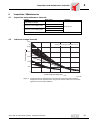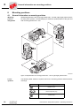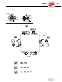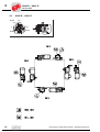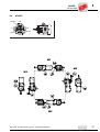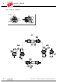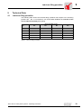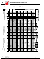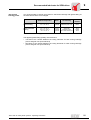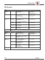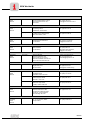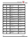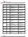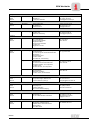
1
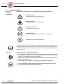
Geared Motors HW30, HS40, HS41, HK40, HS50,
HS60 for Trolley Drive Systems
Edition
07/2000
Operating Instructions
1050 4214 / EN
SEW-EURODRIVE
1
Important Notes................................................................................................. 4
2
Safety Instructions............................................................................................ 5
3
Installation ......................................................................................................... 6
3.1 Before you begin....................................................................................... 6
3.2 Preliminary work ....................................................................................... 6
3.3 Installing the gear unit............................................................................... 6
4
Assembly / Disassembly .................................................................................. 8
4.1 Required tools........................................................................................... 8
4.2 Installing the drive rod............................................................................... 8
4.3 Gear units with solid shafts ....................................................................... 8
5
Commissioning ............................................................................................... 10
5.1
Commissioning of gear units HW30 and helical-worm gear units HS..... 10
I
0
kVA
i
f
n
6
Inspection / Maintenance ............................................................................... 11
6.1 Inspection and maintenance intervals..................................................... 11
6.2 Lubricant change intervals ...................................................................... 11
6.3 Inspection and maintenance ................................................................... 12
7
Operation and Service .................................................................................... 13
7.1 Gear unit malfunction.............................................................................. 13
8
Mounting Positions......................................................................................... 14
8.1 General information on mounting positions ............................................ 14
8.2 HW30 D.. ................................................................................................ 15
8.3 HS40 D.., HS41 D................................................................................... 16
8.4 HK40D... ................................................................................................. 17
8.5 HS50 D.., HS60 D................................................................................... 18
9
Technical Data................................................................................................. 19
9.1 Lubricant filling quantities........................................................................ 19
9.2 Recommended lubricants for SEW drives .............................................. 20
P Hz
Operating Instructions Gear Units for Trolley Drive Systems
3
1
Important Notes
1
Important Notes
Warning
and Safety
Instructions
Always follow the warnings and safety instructions in this publication!
Electrical hazard
Possible effects: Serious or fatal injury.
Immediate danger
Possible effects: Serious or fatal injury.
Dangerous situation
Possible effects: Minor injury.
Harmful situation
Possible effects: Damage to equipment or surroundings.
Application hints and useful information.
Following these instructions is required for fault-free operation and fulfillment of any
warranty claims. Read these instructions carefully before you start working with the unit!
These operating instructions contain vital servicing information and should be kept in the
vicinity of the unit.
Disposal
(please observe all applicable regulations):
• Housing components, gears, shafts and rolling bearings of gear units should
be disposed of as steel scrap. The same applies to components made of
cast iron if no separate collection is available.
• Helical-worm wheels consist partially of non-ferrous metal and should be
disposed of accordingly.
• Collect used oil and dispose of it according to applicable regulations.
•
•
4
In case of design changes, adjust the lubricant filling amounts accordingly.
Please observe the information in Section 3.3!
Gear Units for Trolley Drive Systems - Operating Instructions
Safety Instructions
2
2
Safety Instructions
Preliminary
remarks
The following safety instructions refer primarily to the operation of gear
units.
When operating geared motors, please also observe safety instructions for motors in
the corresponding operating instructions.
Please refer to the additional safety instructions in the individual sections of
these operating instructions.
General
During and after operation, geared motors and gear units contain live and moving
components and possibly hot surfaces.
All tasks related to transport, storage, installation/assembly, connection, startup,
service and maintenance may only be performed by qualified technical personnel
while strictly adhering to
• the pertinent detailed operating instruction(s) and circuit diagrams
• warning and safety labels on the gear unit/geared motor
• system-specific regulations and requirements
• national/regional regulations concerning safety and accident prevention
Serious personal injuries and material damage may occur through
• incorrect use
• wrong installation or operation
• inadmissible removal of required protective covers or of the housing
Intended usage
These geared motors/gear units are intended for industrial systems. They comply with
existing standards and regulations. The technical data and information on approved
conditions can be found on the nameplate and in the documentation.
All these details must be observed!
Transport /
Storage
Inspect shipment for possible transport damages upon receipt. Immediately
inform the shipping company of any damages. Startup may have to be cancelled.
Fasten installed lifting eyebolts. They were designed for the weight of the geared motor/
gear unit; no additional loads may be applied.
If necessary, use appropriate and sufficiently dimensioned means of transport. Remove
existing shipping braces prior to startup.
Installation /
Assembly
Observe information in sections 3 and 4!
Commissioning /
Operation
Check the correct direction of rotation of the gear unit in its disengaged state (without
built-on geared motor). Pay special attention to unusual sliding noises during barring.
Secure the key for the trial run without output components. Do not deactivate monitoring
and protection devices – not even for the trial run.
If in doubt, modifications to normal operation (e.g. increased temperature, noises,
vibrations) may require that the geared motor be switched off. Determine the cause and
confer with SEW, if necessary.
Inspection /
Maintenance
Observe information in section 6!
Gear Units for Trolley Drive Systems - Operating Instructions
5
Before you begin
3
3
Installation
3.1
Before you begin
The drive may
only be installed
if
3.2
•
•
•
the entries on the nameplate of the geared motor match the supply voltage
the drive is not damaged (no damage resulting from transport or storage)
it is certain that the following requirements have been fulfilled:
– with all gear units:
ambient temperature between 0 °C and +40 °C, no
oils, acids, gases, vapors, radiation, etc.
– with special versions:
drive configured according to ambient conditions
– with Spiroplan® gear unit HW30 and helical-worm gear HS..:
no large external mass moments of inertia are present that could exert a restoring
load on the gear unit (with η’ (restoring) = 2 – 1/η < 0.5 self-locking)
Preliminary work
Output shafts and flange surfaces must be thoroughly cleaned of anti-corrosion agents,
contamination or similar impurities (use a commercially available solvent). Do not let the
solvent get in contact with the sealing lips of the oil seals – danger of damage to the
material!
Please note: The service life of the lubricant in the bearings is reduced if the unit is
stored ≥ 1 year.
Gear unit designs of the "extended storage" type have
• an oil fill suitable for the mounting position so the unit is ready to run (mineral oil).
Nevertheless, check the oil level prior to startup (see “Lubricant filling quantities" on
page 19).
• a partially higher oil level if synthetic oil is used. Correct the oil level prior to startup
(see “Lubricant filling quantities" on page 19).
3.3
Installing the gear unit
The gear unit or geared motor must be mounted/installed in the specified mounting
position (Spiroplan® gear units are not dependent upon mounting position) on a level1),
vibration-absorbing and torsionally rigid support structure. Do not tighten housing legs
and mounting flanges against each other.
The oil check and drain screws and the breather valves must be freely accessible!
At this point of assembly, please check that the oil filling is as specified for the mounting
position.
In case of design changes, adjust the lubricant filling amounts accordingly.
Where the mounting position of HS gear units is to be changed to mounting position M2,
please consult the SEW service department.
1) Maximum permitted flatness error for flange mounting (approximate value with reference
to DIN ISO 1101): with → flange 120 – 600 mm max. error 0.2 – 0.5 mm
6
Gear Units for Trolley Drive Systems - Operating Instructions
Installing the gear unit
3
Use plastic inserts (2–3 mm thick) if there is a risk of electrochemical corrosion between
the gear unit and the driven machine (connection between different metals such as cast
iron and high-grade steel)! Also fit the bolts with plastic washers! Ground the housing
additionally – use the grounding bolts on the motor.
Installation in
damp areas or on
the outside
Gear units are supplied in corrosion-resistant versions for use in damp areas or in the
open air. Any damage to the paintwork (e.g. on the breather valve) must be repaired.
Gear unit
venting
All gear units are delivered by SEW ready for the mounting position with the breather
valve and transport fixture fitted.
Exception:
Gear units for extended storage, pivoting and inclined mounting positions are delivered
with a screw plug on the intended vent hole. Prior to startup, the customer must replace
the highest screw plug by the supplied breather valve on each individual gear unit!
• With geared motors (for extended storage, pivoting or inclined mounting position),
the supplied breather valve is located in the terminal box on the motor.
• With mount-on units that must breathe on the input side, a breather valve is
supplied in a plastic bag.
• With gear units in an enclosed design no breather valve is supplied.
Activating the
breather valve
Usually the breather valve is activated ex-works. Should this not be the case, the
transport fixture must be removed from the breather valve prior to the startup of
the gear unit!
1. Breather valve with
transport fixture
2. Remove the transport fixture
02053BXX
Painting the gear
unit
02054BXX
3. Breather valve activated
02055BXX
If the drive is to be overpainted or partially repainted, ensure that the breather valve and
the oil seals are carefully covered with tape. Remove the tape strips after the paint work
is finished.
Gear Units for Trolley Drive Systems - Operating Instructions
7
Required tools
4
4
Assembly / Disassembly
4.1
Required tools
•
•
•
•
•
Wrench set
Mounting device
Shims and distance rings, if necessary
Fixing devices for input and output elements
Lubricant (e.g. NOCO® fluid)
Installation
tolerances
Shaft end
Flanges
Diametric tolerances in accordance with DIN 748
• ISO k6 for solid shafts with d, d1 ≤ 50 mm
• ISO k6 for solid shafts with d, d1 > 50 mm
• Center hole in accordance with DIN 332,
shape DR..
4.2
Centering shoulder tolerances in accordance with
DIN 42948
• ISO j6 with b1 ≤ 230 mm
• ISO h6 with b1> 230 mm
Installing the drive rod
Install the supplied drive rod (with Spiroplan® gear unit HW30 and helical-worm gear unit
HS40/41) into the operating lever and secure it with a lock nut.
4.3
Gear units with solid shafts
Mounting of
carrying wheels
Figure 1 shows an example of a mounting device for the installation of a carrying wheel
onto the gear unit or motor shaft ends. It may be possible to dispense with the thrust
bearing on the mounting device.
1 Shaft end of gear unit
2 Thrust bearing
3 Carrying wheel
2
1
3
03605AXX
Figure 1: Example of a mounting device for installation of carrying wheels
8
Gear Units for Trolley Drive Systems - Operating Instructions
Gear units with solid shafts
4
Figure 2 shows the correct mounting arrangement b of a carrying wheel in order to
avoid impermissible overhung loads.
a wheel hub
FX1
b
FX1
X1
incorrect
wheel hub
X1
correct
03604AEN
Figure 2: Correct mounting arrangement of a carrying wheel
•
•
•
•
Only use a mounting device (see Figure 1) for installing input and output elements.
Use the center bore and the thread on the shaft end for positioning purposes.
Never drive carrying wheels, etc. onto the shaft end by hitting them with a
hammer (damage to bearings, housing and the shaft)!
Power transmission elements should be balanced after fitting and must not give rise
to any impermissible radial or axial forces (see Figure 2 / permitted values see the
"Trolley drive systems" catalog).
Note:
Assembly is easier if you first apply lubricant to the output element or heat it up
briefly (80 to 100 °C).
Input and output elements such as carrying wheels must have protection against
contact!
Mechanical
clutch
The output can be mechanically separated from a continuously running motor by
activating the clutch.
Pole-switchable motors or motors controlled by frequency inverters should be engaged
at low output speeds.
Gear Units for Trolley Drive Systems - Operating Instructions
9
I
5
Startup of gear units HW30 and helical-worm gear units HS..
0
5
Startup
5.1
Startup of gear units HW30 and helical-worm gear units HS..
The direction of rotation of the output shaft on the HS40/41 helical-worm gear
units was changed from CW to CCW in comparison to the predecssor SHB4. Swap
two motor feeder cables to change the direction of rotation.
Running-in
period
The Spiroplan® gear unit HW30 and the helical-worm gear unit HS.. require a runningin period of at least 24 hours before reaching their maximm efficiency. A separate
running-in period for each direction of rotation is required if the gear unit is operated in
both directions of rotation. Table 1 shows the average power reduction during the
running-in period.
Power reduction for
helical-worm gear unit
HS..
i range
Power reduction
Spiroplan® gear unit HW30
1 speed
approx. 12 %
approx.
50...280
approx. 15 %
approx.
40…75
2 speeds
approx. 6 %
approx.
20…75
approx. 10 %
approx.
20…30
3 speeds
-
-
approx. 8 %
approx. 15
4 speeds
-
-
approx. 8 %
approx. 10
5 speeds
approx. 3 %
approx. 6…25
approx. 5 %
approx. 8
Table 1: Power reduction for helical-worm gear units HS.. and
10
i range
Spiroplan®
gear units HW30
Gear Units for Trolley Drive Systems - Operating Instructions
Inspection and maintenance intervals
6
Inspection / Maintenance
6.1
Inspection and maintenance intervals
→ Section
Interval
What to do?
Every 3000 machine hours
At least every six months
Check the oil
Depending on operating conditions
(→ Figure 3) at least every 3 years
Change mineral oil
Depending on operating conditions
(→ Figure 3) at least every 5 years
Change synthetic oil
Spiroplan®
6
Renew the anti-friction bearing
see Section 6.3
Renew the anti-friction bearing
gear units HW30 are lubricated for life and, therefore, are maintenance-free.
Table 2: Inspection and maintenance intervals
6.2
Lubricant change intervals
30000
[h]
Average value per type of lubricant at 70° C
25000
Operating hours
CLP PG
20000
15000
CLP HC
10000
CLP
5000
0
70
80
90
100
110
[°C]
120
Oil bath steady-state temperature
03357AEN
Figure 3: Change intervals for standard gear units under normal environmental conditions.
Change the oil more frequently when using special versions subject to more severe/
aggressive environmental conditions!
Gear Units for Trolley Drive Systems - Operating Instructions
11
Inspection and maintenance
6
6.3
Inspection and maintenance
Do not mix synthetic lubricants with each other and do not mix synthetic and mineral
lubricants!
Oil is the standard lubricant.
The location of the oil level plug, the oil drain plug and the breather plug for the different
mounting positions can be found in the corresponding figures (see section 8.1).
12
Checking
the oil level
1. Disconnect the drive and secure against unintentional switch-on!
Wait until the gear unit has cooled down – Danger of burns!
2. For modified mounting positions refer to Section 3.3!
3. For gear units with oil level plug:
Remove oil level plug, check oil level and adjust if necessary, replace oil level plug.
Checking the oil
1. Disconnect the drive and secure against unintentional switch-on!
Wait until the gear unit has cooled down – Danger of burns!
2. Remove some oil from the oil drain plug.
3. Check the oil consistency:
– viscosity
– if the oil is visibly strongly contaminated, it is recommended to change it sooner
than specified in the maintenance intervals in section 6.1
4. For gear units with oil level plug:
Remove oil level plug, check oil level and adjust if necessary, replace oil level plug.
Changing the oil
Change the oil only when the gear unit is at operating temperature.
1. Disconnect the drive and secure it against unintentional switch-on!
Wait until the gear unit has cooled down – Danger of burns!
Note: However, the gear unit must still be warm, otherwise the high viscosity of
excessively cold oil will make it harder to drain the oil correctly.
2. Place a container underneath the oil drain plug.
3. Remove the oil level screw, breather plug/breather valve and oil drain plug.
4. Drain all the oil.
5. Screw in the oil drain plug.
6. Fill new oil of the same type through the breather hole. In other cases please consult
the SEW service department.
– Fill to oil volume in accordance with the mounting positions (see Section 8.1) or
the details given on the name plate.
– Check at the oil level screw.
7. Screw the oil level plug back in.
8. Install breather plug/breather valve.
Gear Units for Trolley Drive Systems - Operating Instructions
Gear unit malfunction
7
7
Operation and Service
Please provide the following information if you require assistance from our
customer service department:
• Nameplate data (complete)
• State type and extent of the fault
• Time and circumstances of the fault
• Presumed cause
7.1
Gear unit malfunction
Malfunction
Possible cause
Solution
Unusual, regular running
noise
a) Meshing/grinding noise:
Bearing damage
b) Knocking noise:
Irregularity in the gearing
1. Check the oil (→ Section 6.3)
2. Contact customer service
Unusual, irregular running
noise
Foreign bodies in the oil
1. Check the oil (→ Section 6.3)
2. Stop the drive, contact customer
service
•
•
•
•
a) Seal defective
Oil leaking 1)
b) Gear unit not vented
from the motor flange
from the motor oil seal
from the gear unit flange
from the output end
oil seal
Oil leaking
• from the breather valve
for a) Call customer service
for b) Vent the gear unit
(→ Section 8)
for a) Correct the oil level
a) Too much oil
(→ Section 6.3)
b) Breather valve not fitted properly
c) Frequent cold starts (oil foams) and/ for b) Fit the breather valve correctly
(→ Section 8.1)
or high oil level
Output shaft is not rotating
Clutch interrupted
although the motor is running
or the input shaft is rotating
1. Check clutch function On / Off
2. Send in the gear unit/geared
motor for repair
1) It is normal for small amounts of oil/grease to leak out of the oil seal during the running-in phase
(24 hour running time).
Gear Units for Trolley Drive Systems - Operating Instructions
13
General information on mounting positions
8
8
Mounting positions
8.1
General information on mounting positions
Mounting
position
designation
SEW distinguishes the four mounting positions M1 – M4 with right-angle geared motors
for trolley drive systems. The following figure shows the spatial position of the gear unit
with mounting positions M1 – M4.
M1
M2
M4
M3
03564AXX
Figure 9: Representation of mounting positions M1 – M4 for right-angle geared motors.
List of
symbols
The following table shows the symbols used in the mounting position sheets and their
meanings:
Symbol
Meaning
Breather valve
Oil level inspection plug
Oil drain plug
14
Gear Units for Trolley Drive Systems - Operating Instructions
HW30 D..
06 007 000
8.2
Normal
8
HW30 D..
270°
2
0°
180°
1
3
Normal
Normal
Normal
90°
M1
M2
M4
M3
Gear Units for Trolley Drive Systems - Operating Instructions
15
HS40 D.., HS41 D..
06 008 000
8
8.3
Normal
HS40 D.., HS41 D..
270°
2
0°
180°
1
3
Normal
Normal
Normal
90°
M1
M2
M4
M3
16
Gear Units for Trolley Drive Systems - Operating Instructions
HK40D...
06 009 000
8.4
Normal
8
HK40D...
270°
2
0°
180°
1
3
Normal
Normal
Normal
90°
M1
M2
M4
M3
Gear Units for Trolley Drive Systems - Operating Instructions
17
HS50 D.., HS60 D..
06 010 000
8
8.5
HS50 D.., HS60 D..
Normal
270°
2
0°
180°
1
3
Normal
Normal
Normal
90°
M1
M2
M4
M3
18
Gear Units for Trolley Drive Systems - Operating Instructions
Lubricant filling quantities
9
Technical Data
9.1
Lubricant filling quantities
9
The following table shows the lubricant filling quantities with respect to the mounting
positions M1 – M4. It is essential to use the oil level screw as an indicator of the
correct lubricant quantity during filling.
Filling quantity in liter
Gear unit
type
M1
M2
M3
M4
HW30
0.65
0.65
0.65
0.75
HS40
1.2
1.45
0.95
1.9
HS41
1.2
1.45
0.95
1.9
HK40
2.0
2.0
2.3
2.8
HS50
1.4
1.4
1.5
2.2
HS60
2.8
2.7
2.8
4.1
Table 3: Lubricant filling quantities
Gear Units for Trolley Drive Systems - Operating Instructions
19
Recommended lubricants for SEW drives
9
+40
+50
+80
+80
+100
Ambient temperature range
0°C
Standard
+40
+25
+10
+10
+40
+80
+60
+40
+20
+10
+10
Standard
-20
0
0
Standard
+10
+40
+40
+60
+40
Oil
VG 220
VG 220
VG 220
VG 150
VG 150
VG 100
VG 68-46
VG 32
VG 32
VG 22
VG 15
VG 680
VG 680
CLP
VG 460
PG
CLP
VG 150
PG
VG 150
VG 100
VG 220
VG 32
VG 460
VG 460
00
000 - 0
Mobilgear
630
Mobil
Glygoyle 30
Mobil
SHC 630
Mobil
SHC 629
Mobilgear
629
Mobil
D.T.E. 15M
Mobil
SHC 624
Mobil
D.T.E. 11M
Mobilgear
636
Mobil Glygoyle
HE 680
Mobil
SHC 634
Mobil
SHC 629
Mobil
D.T.E. 18M
Mobil
1)
Glygoyle 30
Mobil
SHC 624
3)
Mobilube SHC
75 W90-LS
Glygoyle
2)
Grease 00
Mobilux
EP 004
2)
SAE 75W90
(~VG 100)
VG 460
1)
Lubricant ISO viscosity
type
resp.
DIN (ISO) NLGI class
Lubrication table for SEW drives
Gear
unit
type
-10
-25
*-40
*-40
-20
-30
*-40
-20
-30
*-40
*
*-40
-20
-25
*-40
-20
-30
*-40
*
-20
-25
Standard
= lubricants supplied at the assembly plants SEW USOCOME (F)
= lubricants supplied at the assembly plants SEW EURODRIVE (BRD)
= synthetic lubricants
= mineral lubricants
-15
CLP CLP
PG (CC)
CLP HC
CLP (CC)
CLP CLP HLP CLP
PG (CC) (HM) HC
CLP HC
HCE
API SEW CLP CLP CLP
GL5 PG
HC
PG (CC)
E
DIN
51181
Food
Bio oil ind. oil
Grease
Helical gear units, helical-bevel
gear units, parallel gear units
Helical-worm gear units
W gear
units
R, K, F, S
gear units
R 32
R 302
Shell Omala
220
Shell Tivela
WB
Shell Omala
220 HD
Shell Omala
100
Shell Tellus
T 32
Shell Tellus
T 15
Shell Omala
680
Klüberoil
GEM 1-220
Klübersynth
GH 6-220
Klübersynth
GEM 4-220
Klübersynth
GEM 4-150
Klüberoil
GEM 1-150
Klüberoil
GEM 1-68
Klübersynth
GEM 4-32
ISOFLEX
MT 30 ROT
Klüberoil
GEM 1-680
Klübersynth
GH 6-680
Aral Degol
BG 220
Aral Degol
GS 220
Aral Degol
PAS 220
Aral Degol
BG 100
Aral Degol
BG 46
Aral Degol
BG 680
Shell Omala Klübersynth
460 HD
GEM 4-460
Klübersynth
GEM 4-150
Shell Omala Klüberoil
Aral Degol
100
GEM 1-150 BG 100
Klübersynth
GH 6-220
Klübersynth
GEM 4-32
Klüber SEW
HT-460-5
Aralub
MFL 00
Aral Eural
Shell Cassida Klüberöl
Fluid GL 460 4UH1-460
Gear 460
Klüberbio
CA2-460
Klübersynth
GE 46-1200
Shell Tivela
Compound A
Shell Alvania
GL 00
1) Helical-worm gear units with PG oil. Consult SEW-Eurodrive
2) Consult SEW-Eurodrive for other gear units
3) Special lubricant for Spiroplan gear units only
* Please note: critical startup behaviour at low temperatures.
BP Energol
GR-XP 100
BP Energol
GR-XP 220
BP Enersyn
SG-XP 220
Tribol
1100/220
Tribol
800/220
Tribol
1510/220
Tribol
1100/100
Tribol
800/220
Tribol
1100/680
Tribol
800/680
Tribol
1100/100
Tribol
1100/68
BP Energol
HLP-HM 10
BP Energol
GR-XP 680
BP Enersyn
SG-XP 680
BP Energol
GR-XP 100
BP Energrease
LS-EP 00
Meropa 220
Synlube
CLP 220
Pinnacle
EP 220
Meropa 150
Anubia
EP 46
Cetus
PAO 46
Aircraft
Hydr. Oil 15
Meropa 680
Synlube
CLP 680
Meropa 100
Synlube
CLP 220
Cetus
PAO 46
Multifak
6833 EP 00
Multifak
EP 000
Optigear Synthetic A 220
Optigear
BM 220
Optiflex A
220
Renolin
CLP 150
Renolin
B 46 HVI
Renolin Unisyn
CLP 220
Renolin
CLP 220
01 805 492e
Optigear
BM 100
Optigear
32
Renolin
CLP 680
KBTS/Ga/Vi
CLP = mineral oil
HLP = hydraulic oil
Renolit
SF 7- 041
Renolin
CLP 150
Optigear
BM 680
Optigear
BM 100
Optiflex A
220
Optileb
GT 460
Optisynt
BS 460
Longtime
PD 00
CLP PG = polyglycol
CLP HC = synth. hydrocarbon
E = diester oil (water contamination class WGK 1)
HCE = synth. hydrocarbons + diester oil (USDA - H1 approval)
Gear Units for Trolley Drive Systems - Operating Instructions
20
Recommended lubricants for SEW drives
9.2
Recommended lubricants for SEW drives
Anti-friction
bearing grease
9
It is recommended to change the grease for anti-friction bearings with grease filling at
the same time that the oil is changed.
Gear unit antifriction bearing
Motor anti-friction
bearing
Ambient temperature
Basis
current filling
Manufacturer
-30 °C to +60 °C
-40 °C to +80 °C
mineral
synthetic
Mobilux EP 2
Mobiltemp SHC 100
Mobil
-25 °C to +80 °C
-25 °C to +60 °C
+80 °C to +100 °C
-45 °C to -25 °C
mineral
mineral
synthetic
synthetic
Unirex N3
Alvania R3
Barrierta L55/2
Aero Shell Grease 16
Esso
Shell
Klüber
Shell
Table 4: Anti-friction bearing grease
The applied grease filling quantity must amount to
• one-third of the cavities between the rolling elements for fast running bearings
(motor and gear unit input shaft end)
• two-thirds of the cavities between the rolling elements for slow running bearings
(motor and gear unit input shaft end)
Gear Units for Trolley Drive Systems - Operating Instructions
21
SEW Worldwide
SEW Worldwide
Germany
G
e
r
m
a
n
y
0
1
G
e
r
m
a
n
y
0
2
Headquarters
Production
Sales
Service
Production
Bruchsal
Graben
P.O. Box 3023 · D-76642 Bruchsal
Phone: (0 72 51) 75-0
Fax: (0 72 51) 75-19 70
Telex: 7 822 391
http://www.SEW-EURODRIVE.de
[email protected]
SEW-EURODRIVE GmbH & Co
Ernst-Blickle-Straße 1
D-76676 Graben-Neudorf
Phone: (0 72 51) 75-0
Fax: (0 72 51) 75-29 70
Telex: 7 822 276
SEW-EURODRIVE GmbH & Co
Ernst-Blickle-Straße 42
D-76646 Bruchsal
P.O. Box 1220 · D-76671 Graben-Neudorf
G
e
r
m
a
n
y
0
3
Assembly
Service
Garbsen
(near Hanover)
SEW-EURODRIVE GmbH & Co
Alte Ricklinger Straße 40-42
D-30823 Garbsen
Phone: (0 51 37) 87 98-30
Fax: (0 51 37) 87 98-55
P.O. Box 110453 · D-30804 Garbsen
G
e
r
m
a
n
y
0
4
Kirchheim
(near Munich)
SEW-EURODRIVE GmbH & Co
Domagkstraße 5
D-85551 Kirchheim
Phone: (0 89) 90 95 52-10
Fax: (0 89) 90 95 52-50
G
e
r
m
a
n
y
0
5
Langenfeld
(near Düsseldorf)
SEW-EURODRIVE GmbH & Co
Siemensstraße 1
D-40764 Langenfeld
Phone: (0 21 73) 85 07-30
Fax: (0 21 73) 85 07-55
G
e
r
m
a
n
y
0
6
Meerane
(near Zwickau)
SEW-EURODRIVE GmbH & Co
Dänkritzer Weg 1
D-08393 Meerane
Phone: (0 37 64) 76 06-0
Fax: (0 37 64) 76 06-30
G
e
r
m
a
n
y
0
7
Additional addresses for service in Germany provided on request!
France
Phone: 03 88 73 67 00
Fax: 03 88 73 66 00
http://www. USOCOME.com
[email protected]
F
r
a
n
c
e
0
1
Production
Sales
Service
Haguenau
SEW-USOCOME SAS
48-54, route de Soufflenheim
B.P.185
F-67506 Haguenau Cedex
F
r
a
n
c
e
0
2
Production
Forbach
SEW-USOCOME SAS
Zone industrielle Technopole Forbach Sud
B. P. 30269
F-57604 Forbach Cedex
F
r
a
n
c
e
0
3
Assembly
Service
Technical Office
Bordeaux
SEW-USOCOME SAS
Parc d’activités de Magellan
62, avenue de Magellan - B. P.182
F-33607 Pessac Cedex
Phone: 05 57 26 39 00
Fax: 05 57 26 39 09
F
r
a
n
c
e
0
4
Lyon
SEW-USOCOME SAS
Parc d’Affaires Roosevelt
Rue Jacques Tati
F-69120 Vaulx en Velin
Phone: 04 72 15 37 00
Fax: 04 72 15 37 15
F
r
a
n
c
e
0
4
Paris
SEW-USOCOME SAS
Zone industrielle,
2, rue Denis Papin
F-77390 Verneuil I’Etang
Phone: 01 64 42 40 80
Fax: 01 64 42 40 88
F
r
a
n
c
e
0
5
Additional addresses for service in France provided on request!
08/2000
SEW Worldwide
Argentina
Buenos Aires
SEW EURODRIVE ARGENTINA S.A.
Centro Industrial Garin, Lote 35
Ruta Panamericana Km 37,5
1619 Garin
Phone: (3327) 45 72 84
Fax: (3327) 45 72 21
[email protected]
Melbourne
SEW-EURODRIVE PTY. LTD.
27 Beverage Drive
Tullamarine, Victoria 3043
Phone: (03) 99 33 10 00
Fax: (03) 99 33 10 03
Sydney
SEW-EURODRIVE PTY. LTD.
9, Sleigh Place, Wetherill Park
New South Wales, 2164
Phone: (02) 97 25 99 00
Fax: (02) 97 25 99 05
Vienna
SEW-EURODRIVE Ges.m.b.H.
Richard-Strauss-Strasse 24
A-1230 Wien
Phone: (01) 6 17 55 00-0
Fax: (01) 6 17 55 00-30
[email protected]
Bruxelles
CARON-VECTOR S.A.
Avenue Eiffel 5
B-1300 Wavre
Phone: (010) 23 13 11
Fax: (010) 2313 36
http://www.caron-vector.be
[email protected]
Sao Paulo
SEW DO BRASIL
Motores-Redutores Ltda.
Caixa Postal 201-0711-970
Rodovia Presidente Dutra km 213
CEP 07210-000 Guarulhos-SP
Phone: (011) 64 60-64 33
Fax: (011) 64 80-43 43
[email protected]
Sofia
BEVER-DRIVE GMBH
Bogdanovetz Str.1
BG-1606 Sofia
Phone: (92) 9 53 25 65
Fax: (92) 9 54 93 45
[email protected]:bg
Toronto
SEW-EURODRIVE CO. OF CANADA LTD.
210 Walker Drive
Bramalea, Ontario L6T3W1
Phone: (905) 7 91-15 53
Fax: (905) 7 91-29 99
C
a
n
a
d
a
0
2
Vancouver
SEW-EURODRIVE CO. OF CANADA LTD.
7188 Honeyman Street
Delta. B.C. V4G 1 E2
Phone: (604) 9 46-55 35
Fax: (604) 946-2513
C
a
n
a
d
a
0
3
Montreal
SEW-EURODRIVE CO. OF CANADA LTD.
2555 Rue Leger Street
LaSalle, Quebec H8N 2V9
Phone: (514) 3 67-11 24
Fax: (514) 3 67-36 77
Santiago de Chile
SEW-EURODRIVE CHILE
Motores-Reductores LTDA.
Panamericana Norte No 9261
Casilla 23 - Correo Quilicura
RCH-Santiago de Chile
Phone: (02) 6 23 82 03+6 23 81 63
Fax: (02) 6 23 81 79
Tianjin
SEW-EURODRIVE (Tianjin) Co., Ltd.
No. 46, 7th Avenue, TEDA
Tianjin 300457
Phone: (022) 25 32 26 12
Fax: (022) 25 32 26 11
A
r
g
e
n
t
i
n
a
0
1
Assembly
Sales
Service
Australia
A
u
s
t
r
a
l
i
a
0
1
Assembly
Sales
Service
A
u
s
t
r
a
l
i
a
0
2
Austria
A
u
s
t
r
i
a
0
1
Assembly
Sales
Service
Belgium
B
e
l
g
i
u
m
0
1
Assembly
Sales
Service
Brazil
B
r
a
z
i
l
0
1
Production
Sales
Service
Bulgaria
B
u
l
g
a
r
i
a
0
1
Sales
Canada
C
a
n
a
d
a
0
1
Assembly
Sales
Service
Chile
C
h
i
l
e
0
1
Assembly
Sales
Service
China
C
h
i
n
a
0
1
Production
Assembly
Sales
Service
08/2000
SEW Worldwide
Colombia
C
o
l
o
m
b
i
a
0
1
Assembly
Sales
Service
Bogotá
SEW-EURODRIVE COLOMBIA LTDA.
Calle 22 No. 132-60
Bodega 6, Manzana B
Santafé de Bogotá
Phone: (0571) 5 47 50 50
Fax: (0571) 5 47 50 44
Zagreb
KOMPEKS d. o. o.
PIT Erdödy 4 II
HR 10 000 Zagreb
Phone: +385 14 61 31 58
Fax: +385 14 61 31 58
Prague
SEW-EURODRIVE S.R.O.
Business Centrum Praha
Luná 591
16000 Praha 6
Phone: 02/20 12 12 34 + 20 12 12 36
Fax: 02/20 12 12 37
[email protected]
Copenhagen
SEW-EURODRIVEA/S
Geminivej 28-30, P.O. Box 100
DK-2670 Greve
Phone: 4395 8500
Fax: 4395 8509
Tallin
ALAS-KUUL AS
Paldiski mnt.125
EE 0006 Tallin
Phone: 6 59 32 30
Fax: 6 59 32 31
Lahti
SEW-EURODRIVE OY
Vesimäentie 4
FIN-15860 Hollola 2
Phone: (3) 589 300
Fax: (3) 780 6211
Athens
Christ. Boznos & Son S.A.
12, Mavromichali Street
P.O. Box 80136, GR-18545 Piraeus
Phone: 14 22 51 34-6 + 14 22 51 48-9
Fax: 1-4 22 51 59
[email protected]
Normanton
SEW-EURODRIVE Ltd.
Beckbridge Industrial Estate
P.O. Box No.1
GB-Normanton, West- Yorkshire WF6 1QR
Phone: 19 24 89 38 55
Fax: 19 24 89 37 02
Budapest
SEW-EURODRIVE Ges.m.b. H.
Hollósi Simon Hút 14
H-1126 Budapest
Phone: (01) 2 02 74 84
Fax: (01) 2 01 48 98
Hong Kong
SEW-EURODRIVE LTD.
Unit No. 801-806, 8th Floor
Hong Leong Industrial Complex
No. 4, Wang Kwong Road, Kowloon, Hong
Kong
Phone: 2-7 96 04 77 + 79 60 46 54
Fax: 2-7 95-91 29
[email protected]
Baroda
SEW-EURODRIVE India Private Limited
Plot NO. 4, Gidc
Por Ramangamdi · Baroda - 391 243
Gujarat
Phone: 0 265-83 10 86
Fax: 0 265-83 10 87
[email protected]
Dublin
Alperton Engineering Ltd.
48 Moyle Road
Dublin Industrial Estate
Glasnevin, Dublin 11
Phone: (01) 8 30 62 77
Fax: (01) 8 30 64 58
Croatia
C
r
o
a
t
i
a
0
1
Sales
Service
Czech Republic
C
z
e
c
h
Sales
R
e
p
u
b
l
i
c
0
1
Denmark
D
e
n
m
a
r
k
0
1
Assembly
Sales
Service
Estonia
E
s
t
o
n
i
a
0
1
Sales
Finland
F
i
n
l
a
n
d
0
1
Assembly
Sales
Service
Greece
G
r
e
e
c
e
0
1
Sales
Service
Great Britain
G
r
e
a
t
B
r
i
t
a
i
n
0
1
Assembly
Sales
Service
Hungary
H
u
n
g
a
r
y
0
1
Sales
Service
Hong Kong
H
o
n
g
K
o
n
g
0
1
Assembly
Sales
Service
India
I
n
d
i
a
0
1
Assembly
Sales
Service
Ireland
I
r
e
l
a
n
d
0
1
Sales
Service
08/2000
SEW Worldwide
Italy
I
t
a
l
y
0
1
Assembly
Sales
Service
Milan
SEW-EURODRIVE di R. Blickle & Co.s.a.s.
Via Bernini,14
I-20020 Solaro (Milano)
Phone: (02) 96 98 01
Fax: (02) 96 79 97 81
Toyoda-cho
SEW-EURODRIVE JAPAN CO., LTD
250-1, Shimoman-no,
Toyoda-cho, Iwata gun
Shizuoka prefecture, P.O. Box 438-0818
Phone: (0 53 83) 7 3811-13
Fax: (0 53 83) 7 3814
Ansan-City
SEW-EURODRIVE CO., LTD.
R 601-4, Banweol Industrial Estate
Unit 1048-4, Shingil-Dong
Ansan 425-120
Phone: (031) 4 92-80 51
Fax: (031) 4 92-80 56
Bruxelles
CARON-VECTOR S.A.
Avenue Eiffel 5
B-1300 Wavre
Phone: (010) 23 13 11
Fax: (010) 2313 36
http://www.caron-vector.be
[email protected]
Skopje
SGS-Skopje / Macedonia
Teodosij Sinactaski”
6691000 Skopje / Macedonia
Phone: (0991) 38 43 90
Fax: (0991) 38 43 90
Johore
SEW-EURODRIVE Sdn. Bhd.
95, Jalan Seroja 39
81100 Johore Bahru
Johore
Phone: (07) 3 54 57 07 + 3 54 94 09
Fax: (07) 3 5414 04
Rotterdam
VECTOR Aandrijftechniek B.V.
Industrieweg 175
NL-3044 AS Rotterdam
Postbus 10085
NL-3004AB Rotterdam
Phone: (010) 4 46 37 00
Fax: (010) 4 15 55 52
Auckland
SEW-EURODRIVE NEW ZEALAND LTD.
P.O. Box 58-428
82 Greenmount drive
East Tamaki Auckland
Phone: (09) 2 74 56 272 74 00 77
Fax: (09) 274 0165
[email protected]
Christchurch
SEW-EURODRIVE NEW ZEALAND LTD.
10 Settlers Crescent, Ferrymead
Christchurch
Phone: (09) 3 84 62 51
Fax: (09) 3 84 64 55
[email protected]
Moss
SEW-EURODRIVE A/S
Solgaard skog 71
N-1539 Moss
Phone: (69) 2410 20
Fax: (69) 2410 40
Lima
SEW DEL PERU MOTORES REDUCTORES
S.A.C.
Los Calderos # 120-124
Urbanizacion Industrial Vulcano, ATE, Lima
Phone: (511) 349-52 80
Fax: (511) 349-30 02
Lodz
SEW-EURODRIVE Polska Sp.z.o.o.
ul. Pojezierska 63
91-338 Lodz
Phone: (042) 6 16 22 00
Fax: (042) 6 16 22 10
[email protected]
Japan
J
a
p
a
n
0
1
Assembly
Sales
Service
Korea
K
o
r
e
a
0
1
Assembly
Sales
Service
Luxembourg
L
u
x
e
m
b
o
u
r
g
0
1
Assembly
Sales
Service
Macedonia
M
a
c
e
d
o
n
i
a
0
1
Sales
Malaysia
M
a
l
a
y
s
i
a
0
1
Assembly
Sales
Service
Netherlands
N
e
t
h
e
r
l
a
n
d
s
0
1
Assembly
Sales
Service
New Zealand
N
e
w
Z
e
a
l
a
n
d
0
1
Assembly
Sales
Service
N
e
w
Z
e
a
l
a
n
d
0
2
Norway
N
o
r
w
a
y
0
1
Assembly
Sales
Service
Peru
P
e
r
u
0
1
Assembly
Sales
Service
Poland
P
o
l
a
n
d
0
1
Sales
08/2000
SEW Worldwide
Portugal
P
o
r
t
u
g
a
l
0
1
Assembly
Sales
Service
Coimbra
SEW-EURODRIVE, LDA.
Apartado 15
P-3050-901 Mealhada
Phone: (0231) 20 96 70
Fax: (0231) 20 36 85
[email protected]
Bucharest
Sialco Trading SRL
str. Madrid nr.4
71222 Bucuresti
Phone: (01) 2 30 13 28
Fax: (01) 2 30 71 70
[email protected]
St. Petersburg
ZAO SEW-EURODRIVE
P.O. Box 193
193015 St. Petersburg
Phone: (812) 3 26 09 41 + 5 35 04 30
Fax: (812) 5 35 22 87
[email protected]
Singapore
SEW-EURODRIVE PTE. LTD.
No 9, Tuas Drive 2
Jurong Industrial Estate
Singapore 638644
Jurong Point Post Office
P.O. Box 813
Singapore 91 64 28
Phone: 8 62 17 01-705
Fax: 8 61 28 27
Telex: 38 659
Johannesburg
SEW-EURODRIVE (PROPRIETARY) LIMITED
Eurodrive House
Cnr. Adcock Ingram and Aerodrome Roads
Aeroton Ext. 2
Johannesburg 2013
P.O. Box 27032
2011 Benrose, Johannesburg
Phone: (11) 49 44 380
Fax: (11) 49 42 300
Capetown
SEW-EURODRIVE (PROPRIETARY) LIMITED
Rainbow Park
Cnr. Racecourse & Omuramba Road
Montague Gardens, 7441 Cape Town
P.O.Box 53 573
Racecourse Park, 7441 Cape Town
Phone: (021) 5 11 09 87
Fax: (021) 5 11 44 58
Telex: 576 062
Durban
SEW-EURODRIVE (PROPRIETARY) LIMITED
39 Circuit Road
Westmead, Pinetown
P.O. Box 10433, Ashwood 3605
Phone: (031) 700 34 51
Telex: 622 407
Bilbao
SEW-EURODRIVE ESPAÑA, S.L.
Parque Tecnologico, Edificio, 302
E-48170 Zamudio (Vizcaya)
Phone: 9 44 31 84 70
Fax: 9 44 31 84 71
[email protected]
Jönköping
SEW-EURODRIVE AB
Gnejsvägen 6-8
S-55303 Jönköping
Box 3100 S-55003 Jönköping
Phone: (036) 34 42 00
Fax: (036) 34 42 80
www.sew-eurodrive.se
Basel
Alfred lmhof A.G.
Jurastrasse 10
CH-4142 Münchenstein near Basel
Phone: (061) 4 17 17 17
Fax: (061) 4 17 17 00
http://www.imhof-sew.ch
[email protected]
Chon Buri
SEW-EURODRIVE (Thailand) Ltd.
Bangpakong Industrial Park 2
700/456, M007, Tambol Bonhuaroh
Muang District
Chon Buri 20000
Phone: 0066-38 21 45 29/30
Fax: 0066-38 21 45 31
Romania
R
o
m
a
n
i
a
0
1
Sales
Service
Russia
R
u
s
s
i
a
0
1
Sales
Singapore
S
i
n
g
a
p
o
r
e
0
1
Assembly
Sales
Service
South Africa
S
o
u
t
h
A
f
r
i
c
a
0
1
Assembly
Sales
Service
S
o
u
t
h
A
f
r
i
c
a
0
2
S
o
u
t
h
A
f
r
i
c
a
0
3
Spain
S
p
a
i
n
0
1
Assembly
Sales
Service
Sweden
S
w
e
d
e
n
0
1
Assembly
Sales
Service
Switzerland
S
w
i
t
z
e
r
l
a
n
d
0
1
Assembly
Sales
Service
Thailand
T
h
a
i
l
a
n
d
0
1
Assembly
Sales
Service
08/2000
SEW Worldwide
Turkey
T
u
r
k
e
y
0
1
Assembly
Sales
Service
Istanbul
SEW-EURODRIVE
Hareket Sistemleri San. ve Tic. Ltd. Sti
Bagdat Cad. Koruma Cikmazi No. 3
TR-81540 Maltepe ISTANBUL
Phone: (0216) 4 41 91 63 + 4 41 91 64
+ 3 83 80 14 + 3 83 80 15
Fax: (0216) 3 05 58 67
[email protected]
Uruguay
Please contact our office in Argentina.
U
r
u
g
u
a
y
0
1
USA
U
S
A
0
1
Production
Assembly
Sales
Service
Greenville
SEW-EURODRIVE INC.
1295 Old Spartanburg Highway
P.O. Box 518
Lyman, S.C. 29365
Phone: (864) 4 39 75 37
Fax: Sales (864) 439-78 30
Fax: Manuf. (864) 4 39-99 48
Fax: Ass. (864) 4 39-05 66
Telex: 805 550
U
S
A
0
2
Assembly
Sales
Service
San Francisco
SEW-EURODRIVE INC.
30599 San Antonio Road
P.O. Box 3910
Hayward, California 94544
Phone: (510) 4 87-35 60
Fax: (510) 4 87-63 81
U
S
A
0
3
Philadelphia/PA
SEW-EURODRIVE INC.
Pureland Ind. Complex
200 High Hill Road, P.O. Box 481
Bridgeport, New Jersey 08014
Phone: (856) 4 67-22 77
Fax: (856) 8 45-31 79
U
S
A
0
4
Dayton
SEW-EURODRIVE INC.
2001 West Main Street
Troy, Ohio 45373
Phone: (9 37) 3 35-00 36
Fax: (9 37) 4 40-37 99
U
S
A
0
5
Dallas
SEW-EURODRIVE INC.
3950 Platinum Way
Dallas, Texas 75237
Phone: (214) 3 30-48 24
Fax: (214) 3 30-47 24
U
S
A
0
6
Additional addresses for service in the USA provided on request!
Venezuela
V
e
n
e
z
u
e
l
a
0
1
Assembly
Sales
Service
Valencia
SEW-EURODRIVE Venezuela S.A.
Av. Norte Sur No. 3, Galpon 84-319
Zona Industrial Municipal Norte
Valencia
Phone: (041) 32 95 83 + 32 98 04 + 32
94 51
Fax: (041) 32 62 75
[email protected]
[email protected]
08/2000
SEW-EURODRIVE GmbH & Co · P.O.Box 30 23 · D-76642 Bruchsal/Germany · Tel. +49- 72 51-75-0
Fax +49-72 51-75-19 70 · http://www.SEW-EURODRIVE.com · sew @ sew-eurodrive.com