1
Operating Instructions
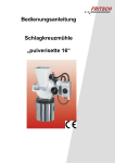
Universal Cutting Mill
" pulverisette 19"
and
Power Cutting Mill
"pulverisette 25"
Fritsch GmbH
Laborgerätebau
Industriestrasse 8
D - 55743 Idar-Oberstein
Phone:
Fax:
E-Mail:
Internet:
*6784/ 70-0
*6784/ 70-11
[email protected]
http://www.fritsch.de
Fritsch GmbH, Laborgerätebau has been certificated by the TÜVZertifizierungsgemeinschaft e.V. on June 24, 1994.
An audit certificated the accordance of the Fritsch GmbH to the DIN EN
ISO 9001.
The enclosed declaration of conformity calls the directives which the
„pulverisette 19“ resp. „pulverisette 25“ corresponds to. This permitts us
to mark the instrument with the CE-Sign.
Instrument number 19.10x.00 / 25.20x.00
Applies as of serial number 0100
Edition 02/2002 Index 004
checked and released
Table of contents
page
1
General Information / Introduction .........................................1
1.1
1.2
1.3
Notes about Operating Instructions...................................................... 1
Explanations of the signs at the instrument and in the operating
instructions............................................................................................ 2
Brief Description of the Instrument ....................................................... 2
1.3.1
1.3.2
1.3.3
Applications ..................................................................................................... 2
Method of Operation ........................................................................................ 3
Drive Motor ...................................................................................................... 3
1.4
Technical Data...................................................................................... 3
2
Operating Safety ......................................................................5
2.1
2.2
2.3
General Safety Instructions .................................................................. 5
Operators.............................................................................................. 6
Protective Equipment ........................................................................... 6
2.3.1
Opening the closure hatch when the machine is not connected to the mains
supply .............................................................................................................. 6
2.4
2.5
Danger Points....................................................................................... 7
Electrical Safety.................................................................................... 7
3
Installation ................................................................................8
3.1
3.2
3.3
3.4
3.5
3.6
3.7
Unpacking............................................................................................. 8
Transport .............................................................................................. 8
Erection................................................................................................. 8
Ambience conditions ............................................................................ 9
Electrical Connection............................................................................ 9
Before Switching On for the First Time ................................................ 9
Switching On for the First Time / Test for Correct Functioning ........... 9
4
Working with the Cutting Mill................................................10
4.1
4.2
Switching On / Switching Off ............................................................. 10
Preparation for Grinding ..................................................................... 10
4.2.1
4.2.2
4.2.3
4.2.4
4.2.5
4.2.6
Inserting / Changing a Sieve Cassette........................................................... 10
Inserting / Changing a Rotor .......................................................................... 11
Closing the Cutting Mill .................................................................................. 11
Mounting of rotating tools and fixed knifes..................................................... 12
Setting the Knife Gap Width........................................................................... 14
Choice of Sieve Cassette............................................................................... 14
4.3
4.4
4.5
Grinding Operation with Standard Funnel .......................................... 15
Combi Funnel for Bulk- and Long Material......................................... 17
Exhaust System (Sample exhauster with cyclone dust chamber) ... 17
5
Cleaning ..................................................................................18
5.1
Cleaning the Exhaust system (Sample exhauster with cyclone dust
chamber)............................................................................................. 19
6
7
8
9
Maintenance ...........................................................................19
Warranty..................................................................................20
Troubleshooting Checklist....................................................20
List of keywords.....................................................................21
pulverisette 19 / pulverisette 25
1
General Information / Introduction
1.1
Notes about Operating Instructions
• The copyright to these technical documents is the property of
Fritsch GmbH, Manufacturers of Laboratory Instruments.
• These operating instructions are not to be reprinted or copied
without the express approval of Fritsch GmbH.
• Please study these instructions carefully before attempting to
operate the machine.
• All operators must be familiar with the contents of the
operating instructions.
• Please observe all notes concerning your safety.
• The cutting mill was designed with the user's safety in mind,
however inherent risks cannot be excluded. Follow the advice
in these instructions to avoid risks to users. The symbols in
the right hand margin highlight the risks described in the text.
Symbols are also to be found on the instrument warning users
of possible risks.
Warning symbols are surrounded by a triangle.
• These operating instructions do not constitute a complete
technical description. They describe only the details required
for safe operation and maintenance for usage under normal
conditions.
pulverisette 19 / pulverisette 25
page 1
1.2
Explanations of the signs at the instrument and
in the operating instructions
Attention!
warning against danger spot
observe operating instructions
Attention! mains voltage
Attention! risk of explosion
Attention! hot surface
Attention! inflammable substances
wear protective gloves!
wear ear protectors!
1.3
Brief Description of the Instrument
1.3.1 Applications
The cutting mill can be used for rapid comminution of soft to
medium-hard and fibrous materials such as: sheet rubber,
plastics, iron-free refuse, confectionery, dried meat, leather,
wood, coal, malt, paper/cardboard, peat, animal feed, pasta,
tablets, sheets, pellets, spices, fabric, straw, maize, bone, roots,
tobacco ...
pulverisette 19 / pulverisette 25
page 2
1.3.2 Method of Operation
The material is fed via a feed funnel (6) into the cutting chamber.
There the material is cut by rotating knives (1) in cooperation with
stationary knives (2). The fine material falls through a sieve
cassette (3) into a collecting basin (5).
1.3.3 Drive
Motor
Universal cutting mill p-19
The machine is driven by a
three-phase a.c. motor or an
a.c. motor with a built-in
mechanical brake.
1.4
Power cutting mill p-25
The p-25 is driven by a threephase a.c. gear motor with no
mechanical brake.
Technical Data
Dimensions and weight
Universal cutting mill p-19
450 mm x 630 mm x 550 mm
(width x height x depth)
56 kg (net weight)
86 kg (gross weight)
Power cutting mill p-25
450 mm x 630 mm x 650 mm
(width x height x depth)
75 kg (Net weight)
105 kg (gross weight)
Noise level
The noise level is approx. 73dB (A) at idle and, including the
cyclone, 95 dB (A) at idle. The value fluctuates considerably
depending on the material being ground.
pulverisette 19 / pulverisette 25
page 3
Nominal voltage / Power consumption / Power output /
Current input or required supply-side fusing
Universal cutting mill p-19
Power cutting mill p-25
400V / 3~ 1800W 1500W 16A 400V / 3~ 2500W 2200W 16A
230V / 3~ 1800W 1500W 16A 230V / 3~ 2500W 2200W 16A
230V / 1~ 2200W 1500W 16A
115V / 1~ 1700W 1100W 15A
(see also section 3.5 Electrical Connection)
Transient overvoltages according to overvoltage category II
allowed.
Electric fuses
• Automatic circuit breaker in the machine
• Micro-Fuse in the machine
• Motor protection switch (see chapter 4.3).
• In machines with a three-phase a.c. motor, a direction of
rotation detection system is fitted (see chapter 2.5 Electrical
Safety)
Material
Universal cutting mill p-19
Feed size (relatively hard
material) max. 10 mm; in other
cases there is no reason why
larger pieces could not be
processed
Batchwise feeding
Power cutting mill p-25
Feed size size (relatively hard
material) max. 20mm; in other
cases there is no reason why
larger pieces could not be
processed
Batchwise feeding
Final fineness
Universal cutting mill p-19
Achievable mean final fineness
0.25-6 mm depending on sieve
insert
Power cutting mill p-25
Achievable mean final fineness
1-10 mm depending on sieve
insert
Speeds
Universal cutting mill p-19
approx. 3000 rpm
pulverisette 19 / pulverisette 25
Power cutting mill p-25
approx. 300 rpm
page 4
2
Operating Safety
2.1
General Safety Instructions
• Read the operating instructions carefully before use.
• The instrument can only to be used for the purpose described
in Chapter 1.3.1 Applications.
• Use only original accessories and original spare parts. Failure
to do so may call into question the performance of the
instrument.
• Do not use damaged accessories.
• The operators must be familiar with the contents of the
operating instructions.
To this end, for example, the operating instructions must be
kept with the instrument.
• Do not remove labels.
• Protective devices must not be made unserviceable or
removed.
• Unauthorized modification of the instrument or any part
thereof will result in the loss of the conformity to European
directives which is asserted by Fritsch and the warranty.
• Wear protective gloves while cleaning the cutting chamber.
• Wear ear protectors if the noise level is higher than 85dB(A).
• Behaviour at all times must be such as to strictly preclude any
risc of accidents.
• Furthermore, the MAC values at place of work specified in the
pertinent safety regulations must be adhered to. Where
applicable, ventilation must be provided or the instrument
must be operated under an exhaust hood.
• When oxidizable materials such as metals, organic materials,
wood, coal, plastic, etc. are ground or sieved, the risk of
spontaneous ignition (dust explosion) exists whenever the fine
particles exceed a specific percentage. While such materials
are being ground or sieved, it is therefore necessary to take
special safety precautions (e.g. wet grinding or wet sieving)
and the work must be supervised by a specialist.
• The instrument is not explosion-proof and is unsuitable to
grind or sieve materials which are explosive, combustible or
promote combustion.
• The safety lock (see arrow in the drawing) becomes warm
when the machine has been in operation for some time. This
is not dangerous.
pulverisette 19 / pulverisette 25
page 5
• p-19: The switch at the back is no mains switch, it is a control
switch. For this reason you have to pull out the mains plug to
disconnect the instrument from mains!
• p-25: The switch at the back is the mains switch. For this
reason the switch has to be easy and quickly to reach.
2.2
Operators
• No one other than authorized persons should operate the
instrument and it must be serviced and repaired by trained
specialists.
• No one suffering from medical problems or under the influence
of medications, drugs, alcohol or overtiredness should be
permitted to operate the instrument.
2.3
Protective Equipment
• Protective equipment must be used as intended and must not
be rendered disabled or dismantled.
• All protective devices should be regularly checked for
completeness and to ensure that they are functioning
correctly.
• The cutting mill is equipped with a safety lock for personal
protection, which locks the front closure hatch during
operation.
• The safety switches prevent operation of the cutting mill when
the grinding chamber is not closed and no collecting basin has
been inserted.
• Do not operate the machine without a feed funnel.
The feed funnels are mechanical protective devices which
permit safe feeding.
• When changing the funnel, disconnect the machine from the
mains supply and fit the new funnel immediately.
• Motor protection switch (see chapter 4.3).
2.3.1 Opening the closure hatch when the machine
is not connected to the mains supply
Attention:
Before you start open the closure as explaned below,
ensure that the closure hatch and the toggle-type fastener
(A) is closed!
1. Insert the attached triangular wrench through the bore located
below the safety lock (see right), and turn clockwise.
2. The closure hatch can now be opened after the toggle-type
fastener (A) of the machine is opened.
3. The cutting mill can now not be switched on. For this, the
safety lock must be activated by turning the triangular wrench
anticlockwise, the closure hatch must be closed and the
toggle-type fastener (A) thrown to fix the closure hatch!
pulverisette 19 / pulverisette 25
page 6
2.4
Danger Points
•
•
•
•
2.5
• First open the closure hatch (1st) fully,
and then open the housing upper
section (2nd). An initial resistance will
be felt when the housing upper section
is being opened.
Ensure that the closure hatch does not swing round violently
and consequently drop out of the hinges.
There is a danger of crushing when the housing upper section
is being closed (see right) - for this reason, the housing upper
section should be closed slowly.
When opening the housing upper section, slowly open it until it
is resting on the rubber buffer (A). Do not let it drop down
violently.
After checking that the rotor (section 4.2.3 Technical Data)
rotates freely, the Allen key must be removed immediately!
Electrical Safety
General
• Press the STOP button: the cutting mill will slow down and
stop.
• Switch off the main switch when the cutting mill is inoperative
for an extended period (e.g. over night).
Protection against Restarting
In the event of a mains failure during operation or after the
machine has been switched off with the main switch, the closure
hatch will remain locked. When the mains voltage is restored, the
lock of the hood will open. For safety reasons, however, the
cutting mill will not start again.
Direction of Rotation Detection
In machines with a three-phase a.c. motor, a direction of rotation
detection system is fitted: If, after the machine has been
connected to the mains supply and the main switch has been
switched on, the START button does not light up, the direction of
rotation must be corrected. For this, two phases must be
changed.
Overload Protection
• In the event of overloading, a motor current protection switch
(see chapter 4.3) will switch off (STOP button will shine).
pulverisette 19 / pulverisette 25
page 7
3
Installation
3.1
Unpacking
• Remove the nails with which the protective packing is
fastened on the transport pallet. The transportation protective
packing is either a wooden box or a cardboard box placed on
the transport pallet.
• Lift the hood off the transport pallet.
• Check that the items supplied correspond to your order before
proceeding.
3.2
Transport
• Transport the machine on the transport pallet using a fork lift
truck or hand fork lift truck.
• To carry the machine, grip it below at the front and the back.
Do not use the housing for carrying.
Carrying the machine will require at least two persons.
3.3
Erection
• The cutting mill is secured to the transport pallet by four
screws. Undo the four screws.
• Lift the cutting mill off the transport pallet.
Lifting the machine down will require at least two persons.
Fastening the Cutting Mill
Screw the cutting mill onto the frame supplied or onto a stable
bench etc.
• Unscrew the oval head screws on the housing and remove the
housing (see right).
• Two U-shaped rails are fitted on the bottom of the machine.
Pass the attached screws through the holes drilled in the Ushaped rails, and screw them into the frame or the bench.
Other screws of the same diameter may also be used.
Please ensure that the machine is fastened securely, as
considerable transverse forces do occur.
Ensure that there is good access to the cutting mill.
Ensure that to the right of the mill, there is sufficient space for the
housing upper section including the funnel to be opened.
Do not block the ventilation louver at the rear. There is a danger of
overheating if the louver is blocked.
pulverisette 19 / pulverisette 25
page 8
3.4
Ambience conditions
•
•
•
•
•
Use the instrument only inside.
The air must not contain any electrical conductive dust.
The ambient temperature must be between 5 and 40°C.
Height up to 2000m M.S.L.
Maximum relative humidity of air 80% temperature up to 31°C,
linear decreasing down to 50% relative humidity of air at 40°C
• Contamination level 2 (IEC 664)
3.5
Electrical Connection
Before making the connection, compare the voltage and current
values shown on the nameplate with the values of the mains
supply to which the machine is to be connected.
(see section 1.4 Fehler! Verweisquelle konnte nicht gefunden
werden.)
If, after the machine has been connected to a three-phase mains
supply and the main switch has been switched on, the START
button does not come on, the direction of rotation must be
corrected. For this, two phases must be changed.
The connecting cable may be changed only by a trained
expert.
3.6
Before Switching On for the First Time
Universal cutting mill p-19
Power cutting mill p-25
• Connect the machine to the mains supply.
• Set the main switch at the • Set the main switch at the
rear of the machine to 0.
rear of the machine to
HAND.
• Pass the attached hexagon socket screw key through the
central hole in the closure hatch. Now turn the hexagon socket
screw key and thus check whether the rotor rotates freely.
• Remove the Allen key again.
• If the rotor does not rotate freely, proceed as described in
section 4.2.4.
This check should also be made every time the rotor is changed.
3.7
Switching On for the First Time /
Test for Correct Functioning
Switch on the machine only when all the work described in
section 3 has been done.
pulverisette 19 / pulverisette 25
page 9
Attention! mains voltage
4
Working with the Cutting Mill
4.1
Switching On / Switching Off
Universal cutting mill p-19
Power cutting mill p-25
• Again check that the cutting mill is located securely.
• Check whether the feed funnel is fitted securely.
• Insert the collecting basin.
• Check whether the toggle-type fastener (A) is closed.
• Connect the machine to the mains supply - the START button
must come on. (see 2.5 Fehler! Verweisquelle konnte nicht
gefunden werden.)
• Set the main switch at the • Set the main switch at the
rear of the machine to
rear of the machine to I.
AUTO.
• Switch on the machine by pressing the START button.
The closure hatch will now be locked.
To switch off the machine, press the STOP button. After waiting
for a few seconds, open the closure hatch.
Switch off the main switch if the cutting mill is to be inoperative
for an extended period (e.g. over night).
Never open the toggle-type fastener during operation, as
this can seriously damage the rotor.
4.2
Preparation for Grinding
4.2.1 Inserting / Changing a Sieve Cassette
Switch on the machine at the main switch. After a few seconds,
open the toggle-type fastener (1). Open the closure hatch (2)
fully, and slowly open the housing upper section (3) (initial
resistance will be felt) until the housing upper section is resting
on the rubber buffer (A).
Pull the sieve cassette out towards the front.
If necessary, use the extracting tool 45.5550.10: Insert the
extracting tool in the two holes in the sieve cassette to beyond
the bends of the extracting tool. When inserting the extracting
tool, move it up and down gently.
If the sieve cassette becomes jammed, remove the material to be
ground below the left-hand stationary knife with a screwdriver.
Before inserting the sieve cassette, clean the cutting chamber
thoroughly so that the machine can be closed tightly again.
pulverisette 19 / pulverisette 25
page 10
4.2.2 Inserting / Changing a Rotor
Universal cutting mill p-19
Power cutting mill p-25
• Set the main switch at the • Set the main switch at the
rear of the machine to I.
rear of the machine to
AUTO.
• Open the toggle-type fastener (1). Open the closure hatch fully
(2), and slowly open the housing upper section (3) until it is
resting on the rubber buffer.
• Pull the rotor out towards the front; wear protective gloves.
If necessary, carefully lever out the rotor.
• Clean the cones of the rotor.
• Clean the two cones of the cutting mill (1st in the closure
hatch and 2nd in the receptacle).
• When inserting the rotor, rotate it until it engages with the
driver pins at the rear. The main switch must be set to
AUTO (p-19).
• Check whether the rotor rotates freely:
Set the main switch to HAND.
Pass the attached hexagon socket screw key through the
central hole in the closure hatch. Now turn the hexagon socket
screw key and thus check whether the rotor rotates freely.
Remove the Allen key again immediately.
If the rotor does not rotate freely, proceed as described in
section Setting the Knife Gap Width.
This check should be made every time the rotor is changed.
4.2.3 Closing the Cutting Mill
Before closing the cutting mill, clean the cutting chamber, the
contact surfaces of the housing, and in particular the closing
surfaces of the lock.
• Slowly close upper section of the housing until it rests in its
closed position.
• Close the closure hatch.
• Hook in the loop of the toggle-type fastener and pull the
handle of the toggle-type fastener over.
• Check whether the rotor rotates freely:
Set the main switch to HAND.
Pass the attached hexagon socket screw key through the
central hole in the closure hatch. Now turn the hexagon socket
screw key and thus check whether the rotor rotates freely.
Remove the Allen key again immediately.
If the rotor does not rotate freely, proceed as described in
section Setting the Knife Gap Width.
This check should be made every time the rotor is changed.
pulverisette 19 / pulverisette 25
page 11
4.2.4 Mounting of rotating tools and fixed knifes
p-19
45.5320.00
p-25
45.7330.00
3
p-19
45.5310.00
1
p-25
45.7310.00
2
p-19
45.5320.00
p-25
45.7320.00
First insert the fixed knifes. Consider the situation of the W+C tungsten
carbide inserts (blue)
The rotary tools of the mills turn in the clockwise direction. Use indexed
knifes or v-shaped rotors by hand and thereby turn in clockwise direction
until the tool at the back engages into the carrier bolts. Close then only
the door of the mill
pulverisette 19 / pulverisette 25
page 12
p-19
45.5160.09
45.5181.09
p-25
45.7180.09
45.7181.09
3
p-19
45.5160.09
45.5161.09
p-25
45.7160.09
45.7161.09
p-19
45.5170.09
1
p-25
45.7170.09
45.7171.09
2
Screws for fixing the fixed knifes
after setting.
Screws for setting the cutting gap.
pulverisette 19 / pulverisette 25
page 13
4.2.5 Setting the Knife Gap Width
Factory settings:
Universal cutting mill p-19
Power cutting mill p-25
• approx. 0.2 mm
• approx. 0.5 mm
Universal cutting mill p-19
Power cutting mill p-25
• Set the main switch to • Set the main switch to I.
HAND.
• Open the closure hatch, and open the housing upper section.
• Loosen the central hexagon socket retaining screws for all
three stationary knives, and unscrew them a short distance.
• Rotate the rotor until the rotor knives and the stationary knives
are located exactly opposite each other.
• Screw in the headless pins to the right and left of the retaining
screws uniformly until they contact the rotor knives. Then turn
the headless pins back uniformly through 1/4 of a revolution
and tighten the retaining screws again.
Using this method, a knife gap of approx. 0.2 mm can be set.
This can be checked with a feeler gauge. This corresponds to 2
sheets printer paper 80gr..
The counter-knives must be parallel with the rotor knives so that
the cutting load is distributed uniformly over the entire length.
• Close the cutting mill
• Pass the attached hexagon socket screw key through the
central hole in the closure hatch. Now turn the hexagon socket
screw key and thus check whether the rotor rotates freely.
• Remove the Allen key again immediately.
4.2.6 Choice of Sieve Cassette
Please note that the sieve cassettes for the machines p-19 and
p-25 differ from each other.
Coarse pieces of material should be precomminuted with a
coarse sieve 2-4 mm and comminuted to the desired final
fineness in a second grinding step.
pulverisette 19 / pulverisette 25
page 14
4.3
Grinding Operation with Standard Funnel
•
•
•
•
•
•
•
•
•
•
•
•
Insert the collecting basin.
Close the cutting mill; see section 4.2.3.
Pull out the slide rod (7) fully.
Move the press plunger (8) into the lower position.
Open the cover, load some material to be ground, and close
the cover again.
The quantity of material to be ground will depend on the feed
grain size and the grindability of the material. It is best to start
with small quantities and increase the quantity depending on
the success of the grinding process.
Switch on the machine (see section 4.1).
Move the slide rod (7) to the right in the direction of the press
plunger (8) until the material to be ground is in front of the
press plunger.
Pull the press plunger (8) upwards, and move the slider fully to
the right until the material to be ground drops into to the
grinding chamber (slight grinding noise will be heard).
Leave the slider at the right, and move the press plunger
downwards (grinding noise will become louder).
Push the press plunger up/down. This pumping results in air
beeing succed in and pumped out by the air filter on the righthand side of the machine.
The air movement is critical to ensuring the fine material
passes through the sieve for collection while the larger
particles are returned for reprocessing.
The grinding operation is finished when the grinding noise
becomes quieter.
Further material to be ground can then loaded into the
machine as above.
pulverisette 19 / pulverisette 25
page 15
Overloading of the cutting mill:
During loading and during the downwards movements of the
press plunger, attention should be paid to the noise of the
grinding process. The volume of the noise corresponds very
closely to the loading of the machine. It is also clear from the
sound pitch if the motor speed is decreasing due to overloading.
Pulling the press plunger back in good time will prevent
overloading of the mill and prolong the life of the grinding parts
and the sieve.
If the cutting mill is overloaded (motor protection switch),
proceed as follows:
1. Unplug power cord
2. Allow the device to cool down
3. Remove the 3 screws on the housing (see image)
4. Carefully lift off the housing (see image)
5. The switch (see image 1) must be set to the “H” position with a
screwdriver (see image 2).
Image 1
pulverisette 19 / pulverisette 25
page 16
Image 2
For fine grinding or material with dust creation the exhaust
system (section 4.5 Exhaust System) may be used.
4.4
Combi Funnel for Bulk- and Long Material
The combi funnel is used for:
1. freeflowing pourable material.
2. grinding long pieces of material such as straw or wood.
For fine grinding < 2 mm, the exhaust system (section 4.5
Exhaust System) must be used.
4.5
Exhaust System
(Sample exhauster with cyclone dust chamber)
• Insert the adapter for the exhauster in the same manner as a
collecting vessel.
• Connect the connecting hose with the adapter and the
exhaust system.
• Close the cutting mill.
• Screw the collecting glass on the cyclone (at the lower end of
the exhaust system), ensure that the connecting hose fits
securely, and switch on the exhaust system.
There are two opposing hose connectors on the exhaust system.
Do not use the closed connection. Leave it closed. Noise Level will
be higher
• Switch on the machine (as in section 4.1) and the exhaust
system.
• Fill in a small quantity of material to be ground by hand, and
note the grinding noises. If the motor speed decreases
audibly, reduce the feed slightly. A rapid eddy with ground
material should form in the collecting glass.
The quantity of material to be ground will depend on the feed
grain size and the grindability of the material. It is best to start
with small quantities and increase the quantity depending on the
success of the grinding process.
pulverisette 19 / pulverisette 25
page 17
When the collecting glass is 2/3 full, grinding must be interrupted
(switch off the cutting mill and the cyclone) and the collecting glass
emptied.
If grinding is not interrupted when the collecting glass is 2/3 full,
the separator effect will decrease and the material will
increasingly clog the filter of the exhaust system.
If the ground material eddying in the collecting glass slowes
down, this means that the air throughflow or the air speed has
decreased:
• the sieve must be cleaned and /or
• the filter of the exhaust system must be cleaned.
The fine fraction (fine dust) of the sample is deposited in the filter
of the exhaust system. Clean the filter from time to time by suction
or blowing.
The exhaust system is especially recommended in combination
with the combination-funnel for long- and bulk solids.
5
Cleaning
When disconnected from mains, the instrument can be wiped
over with a moistened cloth.
It is recommended that the cutting chamber be cleaned with a
vacuum cleaner and dry paint brush or by blowing out with
compressed air.
Do not allow any liquids to seep into the machine.
1. Unscrew the rubber buffer (A).
2. Open the closure hatch and pull it upwards to detach it.
3. (Slowly) open the housing upper section fully.
4. Screw the rod of the press plunger (to the right of the funnel)
fully out of the plunger; at the same time, push the press
plunger out to the left.
5. Grip the press plunger from the left, and pull it out.
The press plunger and the interior of the funnel can then be cleaned.
During reassembly, ensur that all the parts fit securely.
pulverisette 19 / pulverisette 25
page 18
5.1
Cleaning the Exhaust system
(Sample exhauster with cyclone dust chamber)
The exhaust system can be dismantled and cleaned after the
clips are opened. To open and clean the cyclone, two Phillips
screws in the inner base part must be undone.
6
Maintenance
Disconnect mains connector before starting
any work.
Disconnect mains connector and secure
instrument against being turned on again
accidentally
When maintenance work is being
performed, this should be indicated with a
warning sign.
Regular cleaning is the most important
maintenance function for the cutting mill.
Functional
part
Task
Filter of the
cutting mill
Filtering exhaust
air
Test
Maintenance
interval
Cutting gap
Clean the filter insert (C) as
described above; lever it out in an
upwards direction with a
screwdriver or similar tool
Locking the
Check that the closure hatch
closure hatch
remains shut when the main switch
is off?
Securing the lower Check the machine runs without the
opening of the
collecting vessel or the adapter for
cutting chamber
the exhaust system?
Indicating
Check that the START button
readiness for
comes on when the main switch is
operation
on?
Comminuting
Check that the rotor sharp?
material
Maintenance: resharpening
Comminuting
Check that the knife sharp?
material
Maintenance: resharpening
Cutting operation Measure the gap width
Cones
Centring the rotor
Safety lock
Safety
switch
START
button
Rotor
Stationary
knife
pulverisette 19 / pulverisette 25
Check the cones for cleanness and
grooves
page 19
Before each
grinding
operation
Before each use
Before each use
Before each use
Before each use
Before each use
After every rotor
change
After every rotor
change
7
Warranty
The warranty card accompanying this instrument must be returned to the
manufacturer, duly filled out, in order for the warranty to become
effective.
We, Fritsch GmbH, Germany, our application technology laboratory and
our agent in your country will gladly provide advice and assistance with
this instrument.
Always include the serial number shown on the nameplate with any
queries.
8
Troubleshooting Checklist
Malfunction
Possible cause
Elimination of error
START
button not
illuminated
Not connected to
mains
Main switch
Plug in mains plug
In case of threephase a.c. motor:
Incorrect direction of
rotation
Circuit breaker of the
building
Fuse burnt out
START
button
pressed but
Mill does not
start up
hatch not properly
closed
Switch on the main
switch
Change two phases
Press in the circuit
breaker
Remove the housing and
replace the fuse
Clean the contact surface
Close the closure hatch
Push in the collecting
vessel or the adapter for
the exhaust system
properly so that the
switching tongue
engages
Motor stops
Mill protection switch Motor protection switch
STOP button triggered
(see chapter 4.3).
comes on
Eliminate cause of
malfunction
Reduce the feed quantity
Material
Material is extremely
escapes
fine
Uneven
• Cones contaminated
• Rotor imbalance
running with • Bearing in closure • Replace bearing
severe
hatch defective
• Replace rotor
vibration
• Parts broken off
the rotor
Collecting basin or
adapter for the
exhauster not pushed
in properly
There is a copy of the circuit diagrams in the machine.
pulverisette 19 / pulverisette 25
page 20
9
List of keywords
A
Applications ............................................... 2
D
direction of rotation.................................... 7
drive........................................................... 3
E
electrical connection.................................. 9
electrical safety.......................................... 7
exhaust system ................................. 17, 19
M
main switch.............................................. 20
maintenance............................................ 19
material................................................ 4, 17
O
overloading.......................................... 7, 16
P
Protection against Restarting .................... 7
protective device ....................................... 6
Protective devices ..................................... 5
purpose ..................................................... 5
S
Sample exhauster with cyclone dust chamber ........................................................................17, 19
switching on............................................... 9
pulverisette 19 / pulverisette 25
page 21