1
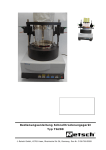
Operating Instructions
Translation of the original
C
B
t
Mill
FRITSCH CROSS BEATER MILL
PULVERISETTE 16
Fritsch GmbH
Milling and Sizing
Industriestrasse 8
D - 55743 Idar-Oberstein
Phone:
+49 (0)6784/ 70-0
Fax
+49 (0)6784/ 70-11
Email:
[email protected]
Internet:
http://www.fritsch.de
Fritsch GmbH, has been certified by the
TÜV-Zertifizierungsgemeinschaft e.V.
Certificat registration number 71 100 J 596.
It was verified through an audit that Fritsch GmbH satisfies the requirements of
DIN EN ISO 9001:2008.
The enclosed declaration of conformity calls the directives
which the „PULVERISETTE 16“ corresponds to.
This permitts us to mark the instrument with the CE-Sign.
Device number 16.300x.00
Applies as of serial number 101
Edition 12/2000 Index 003
PULVERISETTE 16
Table of contents
1
1.1
1.2
1.3
1.4
1.4.1
1.4.2
1.5
1.6
2
2.1
2.2
2.3
2.4
3
3.1
3.2
3.3
3.4
3.5
3.6
4
4.1
4.2
4.3
4.4
4.5
4.6
4.7
Page
General/Introduction ............................................................................3
Notes about the operating instructions ......................................................... 3
Warnings Used ............................................................................................. 4
Explanation of the symbols used on the device and in the operating
instructions.................................................................................................... 5
Brief description of the device....................................................................... 6
Fields of application .............................................................................................6
Method of operation.............................................................................................6
Technical data............................................................................................... 7
Materials and composition ............................................................................ 7
Operating safety ...................................................................................9
General safety instructions ........................................................................... 9
Operators ...................................................................................................... 9
Protective devices....................................................................................... 10
Danger points.............................................................................................. 10
Installation...........................................................................................12
Unpacking ................................................................................................... 12
Transport..................................................................................................... 12
Setup........................................................................................................... 12
Setup on a laboratory table......................................................................... 12
Fastening of the “pulverisette 16” to the universal support......................... 13
Electrical connection ................................................................................... 14
Working with the “pulverisette 16” ...................................................15
Operating elements and operation ............................................................. 15
Operating elements and their function........................................................ 16
Opening and closing the mill housing ......................................................... 17
Inserting the bottom sieve........................................................................... 18
Filter hose and collecting vessel................................................................. 18
Adding material for grinding ........................................................................ 18
Readjusting the impact gap ........................................................................ 19
5
Cleaning ..............................................................................................19
6
Maintenance........................................................................................20
7
Required inspections .........................................................................20
8
Warranty ..............................................................................................21
9
Disclaimer ...........................................................................................21
Page 2
PULVERISETTE 16
1
General/Introduction
1.1 Notes about the operating instructions
• Study the operating instructions carefully.
• The cross beater mill “pulverisette 16” is referred to below as the cross
beater mill.
• All operators must be familiar with the contents of the operating instructions.
• Please follow the notes for your safety.
• The cross beater mill was designed from a perspective of user safety;
however, some residual dangers could not be eliminated. Follow the advice in these instructions to avoid risks to users.
• The symbols in the right hand margin highlight the risks described in the
text.
• Symbols on the device warn about possible dangers or refer to these operating instructions. The symbol in the right page margin (triangle with an
exclamation point) indicates general dangers and refers to the operating
instructions.
• These operating instructions do not constitute a complete technical description. They describe only the details required for safe operation and
maintenance for usage under normal conditions.
• The copyright to these technical documents is the property of Fritsch
GmbH, Laborgerätebau.
• These operating instructions are not to be reprinted or copied without the
express approval of Fritsch GmbH, Laborgerätebau.
Page 3
PULVERISETTE 16
1.2 Warnings Used
The following symbols are used in this description to indicate important information and possible dangers.
DANGER
Indicates a direct danger with high risk that will lead to death
or severe physical injury if not avoided.
WARNING
Indicates a possible danger with moderate risk that could
lead to death or (severe) physical injury if not avoided.
CAUTION
Indicates a danger with low risk that could result in slight or
moderate physical injuries or material damages if not
avoided.
Page 4
PULVERISETTE 16
1.3 Explanation of the symbols used on the device and in
the operating instructions
Attention!
Warning against danger spot
Observe operating instructions
Attention! Mains voltage
Attention! Hazard of explosion
Wear ear protection!
Wear protective gloves!
Spraying with water forbidden!
Do not step below lifted load!
Page 5
PULVERISETTE 16
1.4 Brief description of the device
1.4.1
Fields of application
The cross beater mill serves primarily for preliminary and fine comminution of
medium-hard, brittle materials up to Mohs hardness of 6. Thanks to a large
selection of accessories, the cross beater mill is a device with wide-ranging
fields of application primarily in the areas of chemicals and ceramics, in mining and metallurgy as well as in the preparation of soil samples, etc. in the
laboratory and in industry.
The achievable final fineness depends on the hole width of the bottom sieve
and the grinding properties of the material to be ground. Under good conditions, fineness levels < 100 µm can be achieved.
Typical applications for soft materials:
Needles, leaves, grain, resins, cellulose, chemicals, dried fruits, peat, seeds,
dried plants
Typical applications for medium-hard materials:
Animal feed, salts, pellets, coal, porcelain clay, spices, gypsum, drugs, potash, tablets, slag, minerals, ash, stone and earth (bauxite, limestone, dried
clay, etc.), synthetic resins, pyrite, cement clinker, coke, ores, refractory materials.
1.4.2
Method of operation
The comminution in the cross beater mill takes place through impacting, colliding and shearing effects. After introduction into the filling
funnel, the material enters the grinding chamber, where the comminution process occurs between the cross beater, grinding insert
and bottom sieve.
As soon as the material has reached the corresponding final fineness, it passes through the bottom sieve into the collecting vessel.
A back draft of the air flow generated by the rotating cross beater is
prevented and an acceleration of the material throughput is partially
achieved with the use of a textile filter hose between the cross beater
mill and the collecting vessel.
This ensures a gentle grinding process.
Page 6
PULVERISETTE 16
1.5 Technical data
Dimensions:
“pulverisette 16” approx. 560x420x445mm (height x width x depth)
“pulverisette 16” with base frame approx. 1183x560x700mm (height x width x depth)
Weight:
“pulverisette 16” net approx. 36 kg
with base frame net approx. 58 kg
Operating noise
Noise measurement according to DIN 45635-31-01-KL3
The noise values are also influenced by the properties of the material being ground.
Example:
Noise level LWA = 95dB(A)
Workplace emissions value LpAeq = 86dB(A)
Input material: Quartz pebbles, grain size < 3 mm
Filling level of the grinding chamber: Input quantity until rated motor power
was reached
Drive:
1 and 3 phase alternating current motor with brake
Rotation speed:
2850 rpm
Rated power:
1100 watts
Input grain size:
Max. 20 mm
Collecting vessel volume:
5,000 ml or 30,000 ml
Protection class:
IP 54
1.6 Materials and composition
Collecting vessel 5l and bottom sieves
of stainless steel
Material no.
1.4301
Short name
X 5 CrNi 18 9
Composition
Fe
77,325 %
Cr
18,000 %
Ni
02,500 %
Mn
02,000 %
Si
01,000 %
C
00,070 %
P
00,045 %
S
00,030 %
Page 7
PULVERISETTE 16
Filling funnel and housing of aluminium
Material no..
239
Short name
G-Al Si 10 Mg
Composition
Al
87,300 %
Si
11,000 %
Fe
00,500 %
Mg
00,500 %
Mn
00,400 %
Ti
00,150 %
Zn
00,100 %
Cu
00,050 %
Grinding insert of cast iron
Short name
GG-20
Composition
Fe
93,600 %
C
03,650 %
Si
01,800 %
Mn
00,550 %
P
00,300 %
S
00,100 %
Cross beater of tempered cast iron
Material no..
0.8083
Short name
GTW-38
Composition
Fe
95,465 %
C
03,250 %
Si
00,650 %
Mn
00,400 %
P
00,055 %
S
00,180 %
Impact plates of special steel
Material no...
1.2080
Short name
X 210 Cr 12
Composition
Fe
84,890 %
Cr
12,000 %
C
02,200 %
Mn
00,450 %
Si
00,400 %
P
00,030 %
S
00,030 %
The composition percentages listed above represent average values.
Page 8
PULVERISETTE 16
2
Operating safety
2.1 General safety instructions
•
Study the operating instructions carefully.
•
All operators must be familiar with the contents of the operating instructions.
For this purpose, always keep the operating instructions within easy
reach.
•
Do not remove the instruction labels.
•
Do not disable safety devices.
•
Independent conversions of the device negate the conformity with
European directives declared by Fritsch and void the warranty.
•
The cross beater mill is intended exclusively for use as specified in the
section 1.4.1 .
Any other use is considered improper; the manufacturer accepts no liability for damages resulting from improper use.
•
In addition to the operating instructions, observe and instruct adherence
to all generally applicable statutory and otherwise binding regulations
on accident prevention and environmental protection.
•
If a noise level of 85 dB(A) is reached or exceeded, hearing protection should also be worn to prevent hearing damage.
•
Use original accessories and spare parts only. Failure to adhere to
this may jeopardize the protection of the machine.
•
Do not continue using damaged accessories.
•
The occupational exposure limits of the valid safety instructions must be
observed and if necessary, ventilation should be provided or the machine should be operated under a hood.
•
During comminution of oxidisable substances (e.g. metals or coal),
there exists a danger of self-ignition (dust explosion) if the portion of
fine material exceeds a specific percentage.
•
The cross beater mill is not designed with explosion protection and is
not suitable for grinding of explosive materials.
•
These operating instructions do not contain any repair instructions. Repairs may only be performed by Fritsch GmbH or authorised service
technicians.
2.2 Operators
•
The cross beater mill may only be operated by authorised persons and
maintained and repaired by trained experts.
•
People who are under the influence of health impairments, medications,
drugs, alcohol or excess fatigue may not operate the cross beater mill.
Page 9
PULVERISETTE 16
2.3 Protective devices
•
Protective devices should be used for the intended purpose and must
not be made unserviceable or removed.
•
All protective devices must be regularly inspected for completeness and
proper function. See sections 6 Maintenance and 7 Required inspections.
2.4 Danger points
Process
Action
Dangers
Safety
Damages and injuries resulting
from failure to follow the safety instructions
Please keep the packaging for the
duration of the warranty period
All forms of claims for damages
are excluded
A complaint and return in insufficient packaging can put your
warranty claims at risk
Do not jolt, shake or throw the Electronic
and
mechanical
Transport
“pulverisette 16” during transport
components can be damaged
Temperature fluctua- In event of temperature fluctua- Electronic components can be
tions, protect the “pulverisette 16” damaged
tions
from condensation
In event of incomplete delivery Complaints registered later than
Scope of delivery
and/or transport damages, you this can no longer be accepted
must immediately notify the ship- under some circumstances.
per and Fritsch GmbH (within
24h).
Falling below 5 °C
Electronic
and
mechanical
Ambient temperature
components can be damaged
Exceeding 40 °C
Performance data changes to
an unknown extent.
Exceeding of 80 % at
Electronic
and
mechanical
Humidity
components can be damaged
temperatures up to 31 °C
Performance data changes to
an unknown extent.
Power network does not match Electronic components can be
Electrical connection
the values on the type plate
damaged
Before starting up the device for With an incorrect rotation directhe first time, the rotation direction tion, the grinding performance
must be checked; see the direc- is insufficient and mechanical
tional arrow on the motor.
components may be damaged.
Packaging
Page 10
PULVERISETTE 16
Process
Action
Dangers
Opening and closing Only close the door when the contact surfaces are absolutely free of
of the mill housing
grinding material and other contaminants.
Do not open “pulverisette 16”
while the motor is running.
Adding material
grinding
Cleaning
Mechanical components
the seal can be damaged.
and
In the grinding of toxic or otherwise harmful substances,
there is a risk of inhalation of
dusts that are harmful to health.
Do not open the “pulverisette 16” Risk of injury from the unbraked
and release the motor brake at the cross beater.
same time.
for Add material for grinding slowly Adding too large an amount can
and continuously into the filling bring
the
funnel.
“pulverisette 16” to a stop and
could damage mechanical components.
During grinding, dust-sized grind- Danger of inhalation of harmful
ing material can escape from the dusts.
filling funnel. Use a vacuum hood
when working with toxic or otherwise harmful materials.
Some grinding materials form ex- Risk of explosion.
plosive mixtures in air.
Check the material properties of
your grinding material.
Pull the power plug before every Life-threatening risk of electric
cleaning.
shock
Do not clean with flowing water
Life-threatening risk of electric
shock
Page 11
PULVERISETTE 16
3
Installation
3.1 Unpacking
•
Pull out the nails with which the shell is fastened to the transport pallet. The
shell is the wooden box that is situated over the transport pallet.
•
Lift the shell off the transport pallet.
•
Compare the contents of the delivery with your order.
3.2 Transport
•
Transport with a forklift or elevating truck while on the transport pallet.
•
Use the ring bolt H for transport of the cross beater mill.
Do not stand under the transport pallet!
3.3 Setup
•
Lift the cross beater mill off the transport pallet.
Observe the accident prevention guidelines VBG 8, VBG 9a and VBG 9!
•
Set up the cross beater mill horizontally on a level and stable indoor
surface. It is not necessary to fasten the device in place.
Operation of the cross beater mill while it is on the transport pallet is
not permitted!
•
Ensure easy access to the cross beater mill.
•
The ambient temperature must range from 5–40 °C.
•
The max. humidity up to 31 °C is 80 % and declines linearly to 50 % at
40 °C.
•
The minimum elevation for setup and use of the device is 200 m below
sea level.
3.4 Setup on a laboratory table
You can also mount the cross beater mill onto your laboratory table.
•
Measure the laboratory table thickness.
•
Use screws with a max. diameter of 8 mm and a
length of the laboratory table thickness plus 25 mm.
•
Place the cross beater mill including collecting vessel on the table.
•
Mark the hole locations onto the table using the existing holes on the motor of the cross beater mill.
The spacing from the holes to the front edge of the table must allow sufficient
space for installation and removal of the collecting vessel and the filter hose.
Page 12
PULVERISETTE 16
3.5 Fastening of the “pulverisette 16” to the universal
support
Lift the mill onto the support
with 2 people.
Attention!
Warning against
danger spot
Important!!! Secure the device against tipping until it is
completely screwed in place,
since the mill’s centre of
gravity allows it to tip forward.
Then fasten the mill to the
installation plate with the
supplied fastening materials.
Warning against
hand injury
Mounting
holes
“pulverisette 16”
Page 13
PULVERISETTE 16
3.6 Electrical connection
CAUTION
Electrical Safeguard!
Danger of damages due to short-circuit.
• Ensure that the socket is connected to a power line secured with a circuit breaker.
The electrical connection may only be created by a qualified electrician.
The voltage and frequency of the cross beater mill can be found on the type
plate.
Make certain that the values match the existing power network.
CAUTION
Non-observance of the values on the type plate may damage electrical as well as mechanical components.
Connect the cross beater mill to the power network using the supplied connector cable.
The supplied power cable does not have a plug, since the type of plug depends on the setup location and the respective national regulations.
External fuse protection must be provided during connection of the power
cable to the mains in accordance with the regulations of the setup location.
DANGER
Power Supply Voltage
The connector cable may only be altered by a trained expert.
Direction of rotation of the drive motor
Viewed from the drive side, the 3-phase AC motor should rotate anticlockwise. (Viewed from the front, looking at the cross beater mill, anticlockwise;
viewed from the rear, clockwise.)
The single-phase AC motor is factory-set to rotate anticlockwise.
See:
• DIN VDE 0530 part 8 “Terminal marking and direction of rotation”
• DIN VDE 0530 Teil 7 / EN 60 934-7 “Type codes”.
The direction of rotation of the 3-phase motor can be changes by swaping
two of the leads, L1, L2 and L3 (either at the motor terminals or in the plug).
The direction of rotation may only be changed by a trained electrician.
Page 14
PULVERISETTE 16
4
Working with the “pulverisette 16”
4.1 Operating elements and operation
Graphical view of the operating elements:
Page 15
PULVERISETTE 16
4.2 Operating elements and their function
Item
Element
A
Main switch
with ON/OFF
button
A1
Power switch
with knob
B1
Door
seal
hand wheel
only
with
PULVERISET
TE 16 comfort
Symbol
Function
Disconnects and connects the “pulverisette 16”
from/to the mains
I pressed = “pulverisette 16” is switched on
0 pressed = “pulverisette 16” is switched off
Disconnects and connects the “pulverisette 16”
from/to the mains
ON = “pulverisette 16” is switched on
OFF = “pulverisette 16” is switched off
0 I
Opens and closes the door of the “pulverisette
16” comfort, places tension on the door seal
Pressed and rotated right = closes the door
Pressed and rotated left = opens the door
Receives the grinding material with a maximum
grain size of 20 mm; not intended for storage of a
grinding material reserve;
Reliably prevents backspray of the grinding material.
Prevents a back draft from the air pressure generated by the rotating cross beater, thereby accelerating the material throughput.
D
Filling funnel
at door
E
Filter hose
w/o illustration
F
Collecting
vessel 5 l
w/o illustration
G
Release level
for the motor
brake
Pushing back releases the motor brake, allowing
manual turning of the cross beater for cleaning.
H
Transport bolt
Prevents damage to mechanical and electrical
components during transport.
Receives the ground material.
Page 16
PULVERISETTE 16
4.3 Opening and closing the mill housing
Only open the “pulverisette 16” while it is switched off.
• Press the button 0 on the power switch A or turn to the OFF setting
(see image)
•
Press the hand wheel B1 and turn to the left
•
The hand wheel snaps into the final position
•
Close in reverse order
0
I
Important:
Only close the door when the contact surfaces are absolutely free of
grinding material and other contaminants.
Mechanical components and the seal can be damaged.
Do not open “pulverisette 16” while the motor is running.
In the grinding of toxic or otherwise harmful substances, there is a risk
of inhalation of dusts that are harmful to health.
Do not open the “pulverisette 16” and release the motor brake at the
same time.
Risk of injury from the unbraked cross beater.
Page 17
PULVERISETTE 16
4.4 Inserting the bottom sieve
Bottom sieves BS of stainless steel with Conidur or round perforation are
available as accessories. (See image)
Conidur
0.12/0.2/0.25/0.5/0.75/1/1.5/2 mm
Round hole 3/4/5/6/8/10 mm
•
Stop the “pulverisette 16”
•
Open the mill housing
•
Insert the bottom sieve BS
•
Set the impact gap between the grinding insert and cross
beater to 1mm, with a bottom sieve to cross beater spacing of not < 1 mm.
•
Close mill housing
•
Make certain that a collecting vessel is in place.
•
Start the “pulverisette 16”
Important:
Never operate the device without a bottom sieve inserted! Risk of injury
through possible insertion of fingers from below!
4.5 Filter hose and collecting vessel
Through the use of a textile filter hose between the “pulverisette 16” and the collecting vessel, the airflow generated by
the rotating cross beater is guided away and a back draft is
prevented. In addition, it accelerates the material throughput
and ensures a gentle grinding process.
• Slide filter hose E over the flange, and at the same time
hold the clamping clip at an angle
•
Clamp on seal E1
•
Hang in the collecting vessel F
• Clamp on seals F1
If the collecting vessel is installed without filter hose, you
can expect dust to escape from the filling funnel D.
4.6 Adding material for grinding
The maximum grain size should not exceed 20 mm.
Add grinding material slowly into the filling funnel D (see image)
A rebound blocker in the filling funnel prevents the grinding
material from being thrown back out.
Page 18
PULVERISETTE 16
4.7 Readjusting the impact gap
From time to time, the gap between the grinding insert and the impact plates
of the cross beater should be inspected. (See image)
•
Pull the power plug
•
Open the mill housing
•
Check the gap between the grinding insert ME and the
impact plate PP with a feeler gauge = desired value
~ 1 mm, whereby the gap to the bottom sieve may not
be < 1 mm
Attention:
The gap between grinding insert and impact plate may by
no means exceed 2 mm since this can cause damages to
the instrument.
5
•
Adjust the gap between the grinding insert and impact plate, if necessary.
•
* Screw the impact plates tight with a hex key M5
Cleaning
The cross beater mill can be cleaned while switched off using brushes, small
brushes and possibly vacuumed with an industrial vacuum cleaner or blown
off with compressed air.
Do not allow any liquids to flow into the device.
To clean the grinding chamber in the cross beater mill, the motor brake can be
released with lever G. The cross beater is easy to turn, making cleaning simpler.
The protection class of the cross beater mill is IP54
Page 19
PULVERISETTE 16
6
Maintenance
•
Before the start of maintenance work, pull the power plug and secure the device against accidental reactivation!
•
•
•
Warn about maintenance work with a sign.
Only have maintenance work performed by experts.
Put safety devices back into operation after maintenance and repair
work.
The cross beater mill requires almost entirely no maintenance.
From time to time, the gap between the grinding insert and the impact plates
of the cross beater should be inspected.
Procedure:
• Pull the power plug
•
Open the mill housing
•
Check the gap between the grinding insert ME and the
impact plate PP with a feeler gauge = desired value
1 mm, whereby the gap to the bottom sieve may not be
< 1 mm
Attention:
The gap between grinding insert and impact plate may by no
means exceed 2 mm since this can cause damages to the instrument.
•
7
Adjust the gap between the grinding insert and impact plate, if necessary.
Required inspections
•
•
•
•
Before the start of repair work, pull the power plug and secure the
device against accidental reactivation!
Warn about repair work with a sign.
Put safety devices back into operation after maintenance and repair
work.
Only have repair work performed by experts.
The limit switch and the motor brake should be tested for proper function
every six months.
• Limit switch on the door hinge on the left
o With an opening gap of max. 3 mm, the limit switch must switch off the
motor
• Limit switch on quick latch on the right
o Upon a rotation of the hand wheel of max. 45°, the motor brake must
be activated
• Motor brake
o Start device
o Stop device
o If the braking time exceeds 0.5 seconds, contact a service technician
Page 20
PULVERISETTE 16
8
Warranty
The warranty card enclosed with the machine upon delivery must be completely filled out and returned to the delivering factory so that the warranty
can enter into effect.
Online registration is also possible. More information can be found on your
warranty card or on our website http://www.fritsch.de
The company Fritsch GmbH in Idar-Oberstein and your "Technical Application Laboratory" or the corresponding national representatives would be
happy to provide you with advice and assistance.
Please include the serial number given on the type plate along with any
questions.
NOTE
9
Please note that the original Fritsch packaging must be used
in the event that the machine is returned. Fritsch GmbH is
not responsible for damages resulting from improper packaging (non-Fritsch packaging).
Disclaimer
Before using this product, these operating instructions are to be carefully
read and be understood. Use of the product requires expertise and it is to be
carried out only by commercial users. The product may be used exclusively
for the applications outlined in these instructions and within the scope of the
regulations set out in these operating instructions, and it shall subject to
regular maintenance. In the event of infringements of these instructions
and/or improper use or maintenance, the customer assumes full liability for
the functionality of the product and for such damage or injury as may occur
as a result of breaching these obligations.
The content of these operating instructions is subject as a whole to copyright
protection. This operating manual and its content may not, in any form, in
whole or in part, be reproduced, further distributed or saved without the prior
written consent of Fritsch GmbH
These operating instructions have been compiled to the best of our knowledge and belief and checked for relevance at the time of printing. FRITSCH
GMBH does not accept any warranty or guarantee for the accuracy or completeness of the content in these operating instructions, including, but not
limited to, the tacit warranties of merchantability and suitability for a particular
purpose, unless applicable laws or adjudications prescribe a liability.
FRITSCH GMBH expressly reserves the right to amend and/or to update
these operating instructions without prior notice. The same applies to
changes and improvements to the products described in these operating instructions. The onus for obtaining information about the current status of
these operating instructions lies with the individual user. In this regard,
please contact the FRITSCH GMBH distributor in your area or apply directly
to Fritsch GmbH, Industriestrasse 8 D-55473 Idar-Oberstein, Germany.
Not all parts illustrated must be built into the product. A right to delivery of
these parts does not exist. If interested in them, please contact the FRITSCH
GMBH distributor in your locality or Fritsch GmbH, Industriestrasse 8, D55743 Idar-Oberstein directly.
Page 21
PULVERISETTE 16
FRITSCH GMBH endeavours, with the greatest of care, to continually improve the quality, reliability and safety of their products and to conform with
the state of the art. The products supplied, as well as these operating instructions, correspond with, at the time of transfer from the influence area of
FRITSCH GMBH, the respective state of the art.
Customers agree and acknowledge that, through usage of the product, defects, faults or errors cannot be ruled out entirely.
To avoid the risks thereof, of damage to persons or property being incurred,
or of any other direct or indirect damages, customers must provide for adequate and comprehensive safety measures whilst working with the product.
Fritsch GmbH expressly disclaims every explicit or implied, contractual or
arising from improper handling or a fixed contractual, statutorial or other liability, warranty or other obligation in respect of compensation obligations.
Under no circumstances shall Fritsch GmbH accept liability, resp., are you
entitled to compensation, for any special, direct, indirect, incidental, or consequential damages, including but not limited to lost profits, lost savings, lost
revenues or economic losses of any kind, or for compensation obligations
towards third parties for downtime, goodwill, damage to or replacement of
equipment and property, for the costs or restoration of materials or goods in
connection with the product or the utilisation of our products, for other damage or personal injury (including death) or the like. In so far as the law or adjudications require a mandatory liability, the above disclaimer is to be considered as limited. A liability for negligence is excluded in every case.
No explicit, implied or other rights of usage are granted for patents, trademarks or other intellectual property rights. Likewise, we assume no responsibility for patent infringements or violations of the rights of third parties arising
from the use of this product.
Both adherence with these operating instructions and the conditions and
methods of installation, operation, usage and maintenance of the product
cannot be monitored by Fritsch GmbH. Improper execution of the installation
can lead to property damage and, as a result, also place people at risk. Accordingly, we accept no responsibility or liability for losses, damages or expenses resulting from, or in any way connected with, defective installation
and improper operation, as well as from incorrect utilisation and maintenance.
Page 22