1
Betriebsanleitung
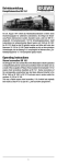
Dampflokomotive BR 19.1
Am 29. August 1941 erließ das Reichsbahnzentralamt in Berlin einen
Umzeichnungsplan für zahlreiche Lokomotiven, die infolge der Besetzung Polens übernommen wurden. Darunter waren, unter der BR 19.1
eingereiht, 54 bemerkenswerte 1´D1´h2 Schnellzuglokomotiven. Zwölf
Lokomotiven der entsprechenden Bauart waren erst 1940 als 39 1001
bis 39 1012 direkt an die DR geliefert worden und liefen jetzt unter den
Nummern 19 155 bis 19 166. Dabei handelte es sich um eine polnische
Schnellzuglok, die als Gattung Pt 31 ursprünglich im Rahmen eines
"Einheitslokprogramms" in 110 Exemplaren gebaut wurde.
Operating Instructions
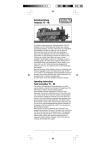
Steam locomotive BR 19.1
On 29 August 1941, the central office of the Reichsbahn in Berlin
published a reclassification plan for numerous locomotives which were
taken over as a result of the occupation of Poland. These included 54
remarkable 1´D1´h2 express train locomotives classified as BR 19.1.
Twelve locomotives of the corresponding construction type had been
delivered directly to the DR in 1940 as 39 1001 to 39 1012 and were
now in service under the numbers 19 155 to 19 166.
This was a Polish express train locomotive, 110 of which had originally
been built as Class Pt 31 as part of a "unit locomotive programme".
1
Inhaltsverzeichnis
Contents
Benennung
Seite
Allgemeine Montage- und Sicherheitshinweise ................................. 2
Arbeiten vor der Inbetriebnahme
• Entnahme der Lok aus der Verpackung ......................................... 4
• Zusatzbauteile montieren ............................................................... 4
• Spezialwerkzeug ............................................................................. 5
Wartungsarbeiten
Lokomotive
• 1. Ölen .......................................................................................... 5
• 2. Gehäuse demontieren .............................................................. 6
• 3. Motor tauschen ........................................................................ 6
• 4. Beleuchtungseinrichtung ......................................................... 6
• 5. Wartungsarbeiten an Radsätze, Getriebe,
und Kuppelgestänge ................................................................ 6
• 6. Kupplungsnormschacht tauschen ........................................... 6
• 7. Haftreifen tauschen ................................................................. 6
• 8. Schleiferwechsel bei Wechselstromausführung ...................... 6
• 9. Raucheinsatz montieren .......................................................... 6
Tender
• 10. Gehäuse demontieren .............................................................. 8
• 11. Tender von Lok trennen ........................................................... 8
• 12. Platine erneuern/ausbauen ...................................................... 8
• 13. Glühbirnen tauschen ................................................................ 8
• 14 Wartungsarbeiten an Radsätze ................................................ 8
• 15. Kupplungsnormschacht tauschen ........................................... 8
• 16. Premium-Digitaldecoder tauschen .......................................... 8
• 17. Digitalbetrieb ............................................................................ 8
Ersatzteilliste ............................................................................ 14 – 22
Bestellhinweis
• Bestellbeispiel ............................................................................... 23
Funktionstastenbelegung für Soundmodelle .................................... 23
Allgemeine Montage- und Sicherheitshinweise
• Diese Bedienungsanleitung beschreibt sämtliche Arbeitsvorgänge
die zur Wartung und Instandhaltung notwendig sind. Bitte lesen Sie
diese Bedienungsanleitung bevor Sie mit den Arbeiten beginnen.
• Bei unsachgemäßem Umgang mit elektrischen Bauteilen können diese zerstört werden. Für entsprechende Arbeiten (z.B.
Platinenwech-sel) können Sie sich an Ihren Fachhändler oder den
Hersteller wenden.
• Bei den folgenden Wartungsarbeiten ist die jeweilige Demontage
beschrieben, der Zusammenbau ist in umgekehrter Reihenfolge
auszuführen.
• Die folgenden Wartungsarbeiten sind bei Gleich- und
Wechselstrom-Ausführungen fast identisch. Im Ausnahmefall wird
im entsprechenden Textabschnitt Bezug genommen.
• Jegliche Kabel oder Verbindungsdrähte die in diesem Produkt
verbaut sind dürfen nicht in eine Netzsteckdose eingeführt werden.
Lebensgefahr!
• Dieses Modell ist auf märklin-Metallgleisen nur bedingt einsatzfähig.
märklin ist eingetragenes Warenzeichen der "Geb. Märklin & Cie. GmbH Göppingen"
2
Description
Page
General assembly and safty information ............................................. 3
Work to be performed before starting up
• Removing the locomotive from the packaging .............................. 4
• Fitting additional parts .................................................................... 4
• Special tool ..................................................................................... 5
Maintenance work
Locomotive
• 1. Lubricating ............................................................................... 5
• 2. Dismantling housing ............................................................... 10
• 3. Exchanging the engine .......................................................... 10
• 4. Light fittings ........................................................................... 10
• 5. Maintenance work on wheelsets, gears,
and coupling rods .................................................................. 10
• 6. Replace the standard coupler shaft ...................................... 10
• 7. Replace the traction tires ...................................................... 10
• 8. Replace pic up in alternating current version ........................ 10
• 9. Mounting smoke insert .......................................................... 10
Tender
• 10. Dismantling housing ............................................................... 12
• 11. Disconnect the tender from the locomotive .......................... 12
• 12. Renew/remove the printed circuit board ............................... 12
• 13. Exchanging the light bulbs ..................................................... 12
• 14. Maintenance work on wheelsets ........................................... 12
• 15. Replace the standard coupler shaft ...................................... 12
• 16. Replace the premium digital decoder ................................... 12
• 17. Digital operation ..................................................................... 12
Spare parts list ......................................................................... 14 – 22
Order notice
• Order example .............................................................................. 23
Function keys for sound models ....................................................... 23
General assembly and safety information
• These operating instructions describe all work steps necessary for
maintenance and repair. Please read these operating instructions
carefully before you start with your work.
• In the case of incorrect handling of electrical components, they may
be destroyed. Please ask your specialist dealer to help with the
necessary work (e.g. changing circuit boards).
• In the case of maintenance work, the disassembly is described
below, to re-assemble the tractor reverse the work steps.
• The maintenance work described below is virtually identical
for direct current and alternating current models. If there are
any differences these will be pointed out specifically.
• All cables and connection wires installed in this product may not be
inserted in a mains socket. Danger!
• This model fits conditionally to märklin metals.
märklin is a registered trademark of the "Geb. Märklin & Cie. GmbH Göppingen"
3
Arbeiten vor der Inbetriebnahme
Work to be performed before starting up
Entnahme der Lok aus der Verpackung (Fig. 1)
Deckel der Verpackung öffnen. Kunststoff-Schutzverpackung
mit Lok entnehmen und auf einen Tisch oder ähnliches abstellen.
Lasche (1) lösen, Deckel und Seitenteile der Schutzverpackung
wegklappen, Lok entnehmen.
Removing the locomotive from packaging (Fig. 1)
Open package lid. Take out plastics protecting package with
engine and put it down on a table or similar item.
Loosen latch (1), fold away lid and side parts of protecting package,
take out engine and take out engine.
Fig. 1
1
Zusatzbauteile montieren (Fig. 2)
In der Verpackung sind zusätzliche Bauteile lose beigelegt. Siehe
Seite 14, Pos. 212.
• 2 = 2 x Bügelkupplung
Werden die Bauteile aus dem Zurüstbeutel für Vitrinenmodelle
montiert, ist die Lok nicht mehr für den Fahrbetrieb geeignet.
• 1 = 2 x Bremsschlauch Knorr rechts
• 3 = 2 x Bremsschlauch Knorr links
• 4 = 2 x Heizschlauch
• 5 = 2 x Originalkupplung
• 6 = 1 x Aufstieg vorn links
• 7 = 1 x Aufstieg vorn rechts
• 8 = 1 x Trittstufe rechts
• 9 = 1 x Trittstufe links
• 10 = 1 x Leiter links
• 11 = 1 x Leiter rechts
• 12 = 1 x Injektorleitung 1
• 13 = 1 x Injektorleitung 2
Fitting additional parts (Fig. 2)
Accessory parts have been loosely enclosed in the packaging. See
page 14, position 212.
• 2 = 2 x Bow coupling
If the components from the add-on bag for display models are
mounted, then the engine will no longer be suitable for operation.
• 1 = 2 x Brake hose Knorr right
• 3 = 2 x Brake hose Knorr left
• 4 = 2 x Heating hose
• 5 = 2 x Original coupling
• 6 = 1 x Front step left
• 7 = 1 x Front step right
• 8 = 1 x Step right
• 9 = 1 x Step left
• 10 = 1 x Ladder left
• 11 = 1 x Ladder right
• 12 = 1 x Injection pipe 1
• 13 = 1 x Injection pipe 2
4
Wartungsarbeiten
Maintenance works
Fig. 2
Spezialwerkzeug (Fig. 3)
Mit dem Schraubedreher (1) können die Schrauben (2) der
Kuppelstangen gelöst und wieder befestigt werden.
Special tool (Fig. 3)
With the screwdriver (1) you can dismantle and fasten the screws (2)
of the coupling rods.
Fig. 3
2
1
1. Ölen (Fig. 4)
Der Motor und die Lagerstellen der Radsätze können an den
gekennzeichneten Punkten sparsam mit Öl der Modellbaubranche
geölt werden. Zum Ölen des Motors ist das Gehäuse abzunehmen,
siehe Seite 6, Punkt 2.
1. Lubricating (Fig. 4)
The engine and the wheelset bearings may be sparingly lubricated at
the marked places with oil used for model making purposes.
In order to lubricate the engine, remove the housing, compare page
10, item 2.
Fig. 4
Motor
Engine
Räder
Wheels
5
Wartungsarbeiten an der Lok
2. Gehäuse demontieren (Fig. 5)
An der Gehäuseunterseite drei Schrauben (80, 111) herausdrehen und
Gehäuse (01) nach oben abnehmen.
3. Motor tauschen (Fig. 5)
Gehäuse (01) demontieren, siehe Punkt 2. Halter für Schnecke (48) ausklipsen
und Schnecke (49) mit Kardan (47) nach oben herausnehmen. Platine (159)
abnehmen. Schrauben (50) herausdrehen und Motor (46) mit Kesselunterteil
(51) abnehmen. Schrauben (52) herausdrehen und Motor abnehmen.
Verkabelung am Motor ablöten.
Achtung: Beim Ausbau des Motors muss auf die Verkabelung
beachtet werden – sonst falsche Fahrtrichtung.
4. Beleuchtungseinrichtung (Fig. 5)
Gehäuse (01) demontieren, siehe Punkt 2.
Glühbirnen vorne: Lampe (121) nach oben abziehen. Glühbirne (13) nach oben
herausziehen und Kabel an Platine (159) ablöten. Einbau in umgekehrter
Reihenfolge.
Glühbirne Führerhaus: Befestigungsschraube (21) herausdrehen. Platine (28)
abnehmen und das Kabel entfernen. Befestigungsschraube (19) herausdrehen und Führerhaus (07) nach oben abnehmen. Abdeckung (12) abziehen
und Glühbirne (13) mit Kabel aus dem Gehäuse herausziehen.
Hinweis: Die Innenbeleuchtung kann im Digitalbetrieb schaltbar gemacht
werden. Dazu den Schiebeschalter im Tender umschalten. Jetzt
kann mit F2 die Innenbeleuchtung geschaltet werden.
5. Wartungsarbeiten an Radsätze, Getriebe und
Kuppelgestänge (Fig. 5)
Bei Wartungsarbeiten an den Radsätzen (96-98) oder dem unteren Getriebe
muss bei Wechselstrommodellen der Schleifer (101) demontiert werden, siehe
Punkt 8. Die Schrauben (81, 110) herausdrehen und die Getriebeabdeckung
(99) abnehmen.
Für Wartungsarbeiten am oberen Getriebe muss das Gehäuse (01) abgenommen werden, siehe Punkt 2. Den Halter für Schnecke (48) ausklipsen und
Schneckenrad (49) mit Kardan (47) entnehmen.
Zum lösen des entsprechenden Radsatzes vom Kuppelgestänge verwenden
Sie bitte den mitgelieferten Schraubendreher, siehe
Seite 5 Spezialwerkzeug.
Der Radsatz (142) kann ohne Demontage des Vorläufers (118) ausgeklipst
werden.
Zur Demontage des Radsatz (93) die Schrauben (95) herausdrehen und
Abdeckung mit Federimitation (94) abnehmen.
Die Demontage der Steuerung (141, 142) wird nicht empfohlen, da es sich
hier um eine konstruktiv komplexe Mechanik handelt. Falls Sie dennoch das
Kuppelgestänge demontieren, bitten wir Sie genau darauf zu achten, wo und
wie jedes Einzelteil montiert war. Die Einbaulage können Sie auch aus der
Ersatzteilgrafik auf Seite 16 entnehmen.
6. Kupplungsnormschacht tauschen (Fig. 5)
Befestigungsschraube (113) herausdrehen und Vorläufer (102) abnehmen.
Bügelkupplung (104) aus Kupplungsnormschacht (103) ausklipsen.
7. Haftreifen tauschen (Fig. 5)
Schraube (68) mit Spezialwerkzeug, siehe Seite 5, herausdrehen. Kuppelstange (71 bzw. 138) zur Seite schieben und Haftreifen (217) wechseln.
8. Schleiferwechsel bei Wechselstromausführung (Fig. 5)
Befestigungsschraube (110) des Schleifers (101) herausdrehen. Kabel am
Schleifer ablöten und Schleifer abnehmen.
9. Raucheinsatz montieren (Fig. 5)
Gehäuse (01) demontieren, siehe Punkt 2.
Raucheinsatz (Pos. 162, Bestell-Nr. 9750.52.03) in Halterung (161)
einsetzen und Gehäuse montieren.
6
Fig. 5
7
Wartungsarbeiten am Tender
10. Gehäuse demontieren (Fig. 6)
Die Schrauben (190) herausdrehen und Gehäuse (02) nach oben
abnehmen.
11. Tender von Lok trennen (Fig. 6)
Soll der Tender von der Lok getrennt werden, muss die Platine (175)
demontiert werden, siehe Punkt 12. Schraube (206) herausdrehen
und Tender von der Lok trennen.
12. Platine erneuern/ausbauen (Fig. 6)
Gehäuse demontieren, siehe Punkt 10. Befestigungsschrauben (174)
herausdrehen und Platine (175) nach oben abnehmen. Sämtliche
Kabel durch Abziehen der Kabelhalter (166) entfernen. Bitte
kennzeichnen Sie sich wo die einzelnen Kabel befestigt waren.
Achtung: Wird die Platine zum Trennen von Tender und Lok
ausgebaut, müssen nur die Kabel an der Platine entfernt
werden, die am Tender angeschlossen sind.
13. Glühbirnen tauschen (Fig. 6)
Gehäuse demontieren, siehe Punkt 10. Kabel/Kabelhalter (166) der
defekten Glühbirne (13) an Platine (175) abziehen.
14. Wartungsarbeiten an Radsätze (Fig. 6)
Entsprechenden Radsatz (194) aus dem Drehgestell (195)
ausklipsen.
15. Kupplungsnormschacht tauschen (Fig. 6)
Gehäuse demontieren, siehe Punkt 10. Befestigungsschrauben (174)
herausdrehen und Abdeckung (208) abnehmen. Kupplungsnormschacht (224) abnehmen und Bügelkupplung (183) ausklipsen.
16. Premium-Digitaldecoder tauschen (Fig. 6)
Gehäuse demontieren, siehe Punkt 10. Premium-Digitaldecoder (219)
abziehen und neuen einstecken.
17. Digitalbetrieb (Fig. 6)
Wechselstrom-Ausführung
Lokomotiven in Wechselstrom-Ausführung AC werden serienmäßig mit
Premium-Digitaldecoder (219) ausgeliefert. Der Decoder erkennt die
Betriebsart (analog/digital) selbstständig. Soll der Decoder umprogrammiert werden, liegt die Einbau- und Betriebsanleitung PremiumDigitaldecoder bei.
Der Decoder ist werkseitig auf Adresse 03 eingestellt.
Gleichstrom-Ausführung
Gehäuse demontieren, siehe Punkt 10. Blindstecker (176) abziehen
und Digitaldecoder einstecken. Den richtigen Einbau des
Digitaldecoders, dessen Einsteckrichtung und Programmierung entnehmen Sie der Betriebsanleitung des Decoderherstellers.
8
Fig. 6
9
Maintenance works on the loco
2. Dismantle housing (Fig. 5)
Unscrew the three screws (80, 111) on the underside of the housing
and remove the housing (01) from the top.
3. Replace engine (Fig. 5)
Dismantle the housing (01), see item 2. Unclip the holder for worm
gear (48) and remove the worm gear (49) with cardan (47) from the
top. Remove the pcb (159). Unscrew the screws (50) and remove
the motor (46) with the boiler under cover (51). Unscrew the screws
(52) and remove the motor. Unsolder the wiring on the engine.
Attention: When dismantling the engine, note the wiring layout otherwise incorrect direction of travel.
4. Light fittings (Fig. 5)
Dismantle the housing (01), see item 2.
Bulbs front: Remove the lamp (121) from the top. Pull out the bulb
(13) and unsolder the wiring on the printed circuit board (pcb) (159).
Driver's cab bulb: Unscrew the fixing screw (21). Remove the pcb
(28) and remove the cable. Unscrew the fixing screw (19) and
remove the driver's cab (07) from the top. Pull off the cover (12) and
pull the bulb (13) and cable out of the housing.
Note: The interior lightning may be switchable by digital operating.
Switch the sliding switch at the tender. With F2 the interior
lightning can switched.
5. Maintenance work on wheelsets, gears and
coupling rods (Fig. 5)
The pic up (101) must be removed for maintenance work on the
wheelsets (96-98) or the lower gears, see item 8. Unscrew the
screws (81, 110) and remove the gears cover (99).
For maintenance work on the upper gears, the housing (01) must be
removed, see item 2. Unclip the holder for worm gear (48) and
remove the worm gear (49) with cardan (47).
To unscrew the wheelsets from the coupling rods, please use the
special tool, see page 5.
The wheelset (142) can also be unclipped without dismantling the
bogie (118).
Dismantling the wheelset (93) unscrew the screw (95) and remove
the cover with spring imitation (94).
Dismantling the coupling rod (141, 142) is not recommended, as the
mechanics are complex. However, if you do dismantle the coupling
rods, please precisely note where and how each individual part was
fitted. The installation position is also given in the spare parts
diagram on page 16.
6. Replace the standard coupling shaft (Fig. 5)
Unscrew the fixing screw (113) and remove the advancing wheel
(102). Unclip the bow coupling (183) from the standard coupling
shaft (103).
7. Replace the traction tyres (Fig. 5)
Unscrew the screw (68) with the special tool, see page 5. Push the
coupling rod (71 or 138) to the side and replace the traction tyres
(217).
8. Replace pic up in alternating current version (Fig. 5)
Unscrew the fixing screw (110) of the pic up (101), unsolder the
cable on the slider and remove the slider.
9. Mounting smoke insert (Fig. 5)
Remove the housing, see section 3. Insert the smoke unit (item 162,
Order No. 9750.52.03) in the holder (161) and fit housing.
10
Fig. 5
11
Maintenance works on the tender
10. Dismantle housing (Fig. 6)
Unscrew the screws (190) and take out the housing (02) from the
top.
11. Disconnect the tender from the locomotive (Fig. 6)
If the tender is to be disconnected from the locomotive, the printed
circuit board (175) must be dismantled, see item 12. Unscrew the
screw (206) and disconnect the tnder from the locomotive.
12. Renew/remove printed circuit board (Fig. 6)
Dismantle the housing, see item 10. Unscrew the fixing screws (174)
and take out the printed circuit board (175) from the top. Remove all
cables by pulling off the cable support (166). Please mark where the
individual cables were fixed.
Attention: If the printed circuit board is dismantled to disconnect the
tender and locomotive, only the cables at the printed
circuit board which are connected to the tender have to
be removed.
13. Exchanging the light bulbs (Fig. 6)
Dismantle the housing, see item 10. Pulling off the cable/cable
support (166) of the damaged bulb (13) at the pcb (175).
14. Maintenance work on wheelsets (Fig. 6)
Unclips the according wheelset (194) from the bogie (195).
15. Replace the standard coupling shaft (Fig. 6)
Dismantle the housing, see item 10. Unscrew the fixing screws (174)
and remove the cover (208). Take off the standard coupling shaft
(224) and unclip the bow coupling (183).
16. Replace the premium digital decoder (Fig. 6)
Dismantle the housing, see item 10. Pull off the premium digital
decoder (219) and plug in the new one.
17. Digital operation (Fig. 6)
Alternating current version
Locomotives of the alternative current version AC are supplied with a
premium digital decoder (219) as a standard. The decoder
recognises the type of operation (analog/digital) independently. If the
decoder re reprogrammed, refer to the installation and operating
instructions for the premium digital decoder.
The decoder is set to address 03 in the factory.
Direct current version
Dismantle the housing, see item 10. Pull off the dummy plug (176)
and plug in the digital decoder. Correct installation of the digital
decoder, its plug-in direction and programming are given in
the digital decoder manufacturer’s operating instructions.
12
Fig. 6
13
Ersatzteilliste Dampflokomotive BR 19.1
Spare Parts List Steam engine BR 19.1
Gleichstrom / Wechselstrom
Lokomotive / Locomotive
D.C. current / A.C. current
14
15
Ersatzteilliste Dampflokomotive BR 19.1
Spare Parts List Steam engine BR 19.1
Gleichstrom / Wechselstrom
Lokomotive / Locomotive
D.C. current / A.C. current
16
Gleichstrom / Wechselstrom
Tender / Tender
D.C. current / A.C. current
17
Ersatzteilliste Dampflokomotive BR 19.1
Spare Parts List Steam engine BR 19.1
Pos. Bestell Nr.
Order no.
Benennung
1
2
3
Dachentlüftung
Ventilation
Abdeckung
Cover
Griffstange Führerhaus
Cabin handle
Griffstange Führerhaus 40404 Cabin handle 40404
Windabweiser
Wind shield
Seitenfenster
Side window
Frontfenster rechts
Front window right
Führerhaus kpl.
Drivers cabin cpl.
Führerhaus 40404 kpl.
Drivers cabin 40404 cpl.
Führerhaus 40408 kpl.
Drivers cabin 40408 cpl.
Führerhaus 40410 kpl.
Drivers cabin 40410 cpl.
Führerhaus 40412 kpl.
Drivers cabin 40412 cpl.
Frontfenster links
Front window links
Fenster hinten rechts
Rear window right
Fenster hinten links
Rear window links
Lampenhalter
Holder for lamp
Lampenschirm
Lamp cover
Lampe
Bulb
Handrad
Hand wheel
Leitung Stehkessel
Pipe cabin
Abdeckung
Hatch
Kessel kpl.
Boiler cpl.
Kessel 40404 kpl.
Boiler 40404 cpl.
Kessel 40408 kpl.
Boiler 40408 cpl.
Kessel 40410 kpl.
Boiler 40410 cpl.
Kessel 40412 kpl.
Boiler 40412 cpl.
Leitung
Pipe
Schraube
Screw
Leitung
Pipe
Leitung
Pipe
Handgriff
Handrail
Griffstange Kessel links
Handrail boiler links
Griffstange Kessel links 40404 Handrail boiler left 40404
Sandfallrohr 2 links
Sandpipe 2 links
Sandfallrohr 1 links
Sandpipe 1 links
Kesselleiter
Boiler ladder
Leitung
Pipe
Platine
PCB
Dampfrohr
Steam pipe
Rauchkammertür
Smoke box door
Rauchkammertür 40404
Smoke box door 40404
Rauchkammertür 40408
Smoke box door 40408
Rauchkammertür 40410
Smoke box door 40410
Rauchkammertür 40412
Smoke box door 40412
Griffstange Rauchkammertür Handrail smoke box door
Handrad Rauchkammertür
Hand wheel smoke box door
Ventil
Valve
Leitung
Pipe
Ventil
Valve
Ventil 40404
Valve 40404
Ventil
Valve
Ventil 40404
Vlave 40404
Leitung
Pipe
Griffstange Kessel rechts
Handrail boiler right
Griffstange Kessel rechts 40404 Handrail boiler right 40404
Ventil
Valve
Sandfallrohr 1 rechts
Sand pipe 1 right
Sandfallrohr 2 rechts
Sand pipe 2 right
Kamin
Chimney
Halter f. Sicherheitsventil
Holder f savety valve
Sicherheitsventil
Savety valve
Pfeife
Whistle
Motor kpl.
Motor cpl.
Kardan
Cardan
Halter f. Schnecke
Holder f. worm gear
Schnecke kpl.
Worm gear cpl.
Schraube
Screw
Kesselunterteil
Boiler under cover
Kesselunterteil 40410
Boiler under cover 40410
Schraube
Screw
Schraube
Screw
4
5
6
7
8
9
10
11
12
13
14
15
16
17
18
19
20
21
22
23
24
25
26
27
28
29
30
31
32
33
34
35
36
37
38
39
40
41
42
43
44
45
46
47
48
49
50
51
52
53
40400.50.01
40400.50.02
40400.50.03
40404.50.03
40400.50.04
40400.50.05
40400.50.06
40400.50.07
40404.50.07
40408.50.07
40410.50.07
40412.50.07
40400.50.08
40400.50.09
40400.50.10
40400.50.11
40400.50.12
3268.99.00
40400.50.13
40400.50.14
40400.50.15
40400.50.16
40404.50.16
40408.50.16
40410.50.16
40412.50.16
40400.50.17
40400.50.18
40400.50.19
40400.50.20
40400.50.21
40400.50.22
40404.50.22
40400.50.23
40400.50.24
40400.50.25
40400.50.26
40400.50.27
40400.50.28
40400.50.29
40404.50.29
40408.50.29
40410.50.29
40412.50.29
40400.50.30
40400.50.31
40400.50.32
40400.50.33
40400.50.34
40404.50.34
40400.50.35
40404.50.35
40400.50.36
40400.50.37
40404.50.37
40400.50.38
40400.50.39
40400.50.40
40400.50.41
40400.50.42
40400.50.43
40400.50.44
40400.50.45
40400.50.46
40400.50.47
40400.50.48
40400.50.49
40400.50.50
40410.50.50
40400.50.51
40400.50.52
Description
18
Pos. Bestell Nr.
Order no.
Benennung
Description
54
55
56
Abdeckung
Abdeckung
Umlauf
Umlauf 40404
Umlauf 40408
Umlauf 40410
Abdeckung Umlauf
Leitung 1 Pumpe
Pumpe
Leitung 2 Pumpe
Windleitblech links
Windleitblech links 40404
Windleitblech links 40410
Handgriff
Leiter links
Leiter links 40404
Injektorleitung 1
Inlektorleitung 1 40404
Injektorleitung 2
Injektorleitung 2 40404
Kesselstütze
Kesselstütze 40404
Halter für Steuerung
Halter für Steuerung 40404
Schraube für Kuppelstange
Feder
Abdeckung
Kuppelstange links
Hülse
Kurbelzapfen mit Schwinge links
Treibstange links
Bremsklotz 4 links
Bremsklotz 4 links 40404
Bremsklotz 3 links
Bremsklotz 3 links 40404
Bremsklotz 2 links
Bremsklotz 2 links 40404
Bremsklotz 1 links
Bremsklotz 1 links 40404
Schraube
Schraube
Schraube
Deichsel
Deichsel 40404
Welle 1
Welle 2
Zahnrad 1
Zahnrad 2
Zahnrad
Drehgestell
Drehgestell 40404
Abdeckung
Abdeckung 40404
Stütze links
Stütze links 40404
Feder
Radsatz DC
Radsatz AC
Radsatz DC 40404
Radsatz AC 40405
Radsatz DC 40408/40410
Abdeckung mit Federimitation
Abdeckung
mit Federimitation 40404
Schraube
Radsatz mit Haftreifennut DC
Radsatz mit. Haftreifennut AC
Radsatz mit Haftreifennut DC
Radsatz mit
Haftreifennut AC 40405
Radsatz 40408/40410
Cover
Cover
Walk way
Walk way 40404
Walk way 40408
Walk way 40410
Cover walk way
Pipe 1 pump
Pump
Pipe 2 pump
Wind shield left
Wind shield left 40404
Wind shield left 40410
Handrail
Ladder left
Ladder left 40404
Injection pipe 1
Injection pipe 1 40404
Injection pipe 2
Injection pipe 2 40404
Boiler support
Boiler support 40404
Crosshead slide bar support
Crosshead slide bar support 40404
Screw for couple rod
Spring
Cover
Couple rod left
Bush
Gear return crank left
Connecting rod left
Brake block 4 left
Brake block 4 left 40404
Brake block 3 left
Brake block 3 left 40404
Brake block 2 left
Brake block 2 left 40404
Brake block 1 left
Brake block 1 left 40404
Screw
Screw
Screw
Shaft
Shaft 40404
Gear shaft 1
Gear shaft 2
Gear 1
Gear 2
Gear
Bogie
Bogie 40404
Cover
Cover 40404
Support left
Support left 40404
Spring
Wheelset DC
Wheelset AC
Wheelset DC 40404
Wheelset AC 40405
Wheelset DC 40408/40410
Cover with spring imitation
Cover
with spring imitation 40404
Screw
Wheelset with traction tire DC
Wheelset with traction tire AC
Wheelset with traction tire DC
Wheelset with
traction tire AC 40408
Wheelset 40408/40410
57
58
59
60
61
62
63
64
65
66
67
68
69
70
71
72
73
74
75
76
77
79
80
81
82
83
84
85
86
87
88
89
90
91
92
93
94
95
96
40400.50.53
40400.50.54
40400.50.55
40404.50.55
40408.50.55
40410.50.55
40400.50.56
40400.50.57
40400.50.58
40400.50.59
40400.50.60
40404.50.60
40410.50.60
40400.50.61
40400.50.62
40404.50.62
40400.50.63
40404.50.63
40400.50.64
40404.50.64
40400.50.65
40404.50.65
40400.50.66
40404.50.66
40400.50.67
40400.50.68
40400.50.69
40400.50.70
40400.50.71
40400.50.72
40400.50.73
40400.50.74
40404.50.74
40400.50.75
40404.50.75
40400.50.76
40404.50.76
40400.50.78
40404.50.78
40400.50.79
40400.50.80
40400.50.81
40400.50.82
40404.50.82
40400.50.83
40400.50.84
40400.50.85
40400.50.86
40400.50.87
40400.50.88
40404.50.88
40400.50.89
40404.50.89
40400.50.90
40404.50.90
40400.50.91
40400.50.92
40401.50.92
40404.50.92
40405.50.92
40408.50.92
40400.50.93
40404.50.93
40400.50.94
40400.50.95
40401.50.95
40404.50.95
40405.50.95
40408.50.95
19
Ersatzteilliste Dampflokomotive BR 19.1
Spare Parts List Steam engine BR 19.1
Pos. Bestell Nr.
Order no.
Benennung
Description
97
Radsatz DC
Radsatz AC
Radsatz DC 40404
Radsatz AC 40405
Radsatz 40408/40410
Radsatz DC
Radsatz AC
Radsatz DC 40404
Radsatz AC 40405
Radsatz 40408/40410
Getriebeabdeckung
Getriebeabdeckung 40404
Radsatz DC
Radsatz AC
Radsatz DC 40404
Radsatz AC 40405
Radsatz 40408/40410
Schleifer AC
Vorläufer
Vorläufer 40404
Kupplungsschacht
Kupplungsschacht 40404
Abdeckung
Abdeckung
Schraube
Abdeckung
Schraube
Stütze rechts
Stütze rechts 40404
Schraube
Schraube
Schraube
Schraube
Aufstieg vorn links
Aufstieg vorn links 40404
Puffergriff vorn
Abdeckung
Schraube
Aufstieg vorn rechts
Aufstieg vorn rechts 40404
Puffer links
Puffer links 40404
Puffer rechts
Puffer rechts 40404
Lampe für 40400
Lampe für 40404
Lampe für 40408
Lampe für 40412
Abdeckung
Abdeckung
Abdeckung
Leitung
Zylinder links
Zylinder links 40404
Zylinder links 40410
Abdeckung
Abdeckung
Kolbenstangenschutzrohr
Luftventil
Zylinderentwässerung links
Feder
Bremsklotz 1 rechts
Bremsklotz 1 rechts 40404
Bremsklotz 2 rechts
Bremsklotz 2 rechts 40404
Bremsklotz 3 rechts
Bremsklotz 3 rechts 40404
Bremsklotz 4 rechts
Bremsklotz 4 rechts 40404
Kuppelstange rechts
Treibstange rechts
Wheelset DC
Wheelset AC
Wheelset DC 40404
Wheelset AC 40405
Wheelset 40408/40410
Wheelset DC
Wheelset AC
Wheelset DC 40404
Wheelset AC 40405
Wheelset 40408/40410
Gear box cover
Gear box cover 40404
Wheelset DC
Wheelset AC
Wheelset DC 40404
Wheelset AC 40405
Wheelset 40408/40410
Pic up AC
Advancing wheel
Advancing wheel 40404
Standard coupling shaft
Standard coupling shaft 40404
Cover
Cover
Screw
Cover
Screw
Support right
Support right 40404
Screw
Screw
Screw
Screw
Front step left
Front step left 40404
Buffer handle front
Cover
Screw
Front step right
Front step left 40404
Buffer left
Buffer left 40404
Buffer right
Buffer right 40404
Lamp for 40400
Lamp for 40404
Lamp for 40408
Lamp for 40412
Cover
Cover
Cover
Pipe
Cylinder left
Cylinder left 40404
Cylinder left 40410
Cover
Cover
Pisten rod cover pipe
Air valve
Cylinder drain cocks left
Spring
Brake block 1 right
Brake block 1 right 40404
Brake block 2 right
Brake block 2 right 40404
Brake block 3 right
Brake block 3 right 40404
Brake block 4 right
Brake block 4 right 40404
Couple rod right
Connecting rod right
98
99
100
101
102
103
104
105
106
107
108
109
110
111
112
113
114
115
116
117
118
119
120
121
122
123
124
125
126
127
128
129
130
131
133
134
135
136
137
138
139
40400.50.96
40401.50.96
40404.50.96
40405.50.96
40408.50.96
40400.50.97
40401.50.97
40404.50.97
40405.50.97
40408.50.97
40400.50.218
40404.50.218
40400.50.98
40401.50.98
40404.50.98
40405.50.98
40408.50.98
2225
40400.50.99
40404.50.99
40400.50.100
40404.50.100
40400.50.101
40400.50.102
40400.50.103
40400.50.104
40400.50.105
40400.50.106
40404.50.106
40400.50.107
40400.50.108
40400.50.109
40400.50.110
40400.50.111
40404.50.111
40400.50.112
40400.50.113
40400.50.114
40400.50.115
40404.50.115
40400.50.116
40404.50.116
40400.50.117
40404.50.117
40400.50.118
40404.50.118
40408.50.118
40412.50.118
40400.50.119
40400.50.120
40400.50.121
40400.50.122
40400.50.123
40404.50.123
40410.50.123
40400.50.124
40400.50.125
40400.50.126
40400.50.127
40400.50.128
40400.50.130
40400.50.131
40404.50.131
40400.50.132
40404.50.132
40400.50.133
40404.50.134
40400.50.134
40404.50.134
40400.50.135
40400.50.136
20
Pos. Bestell Nr.
Order no.
Benennung
Description
140 40400.50.137 Kurbelzapfen
mit Schwinge rechts
141 40400.50.138 Steuerung kpl. links
142 40400.50.139 Steuerung kpl. rechts
143 40400.50.140 Zylinderentwässerung rechts
144 40400.50.141 Tachometer
40404.50.141 Tachometer 40404
145 40400.50.142 Leiter rechts
40404.50.142 Leiter rechts 40404
146 40400.50.143 Drahtbügel für Lampe
40404.50.143 Drahtbügel für Lampe 40404
147 40400.50.144 Trittstufe
148 40400.50.145 Trittstufe rechts
149 40400.50.146 Trittstufe links
150 40400.50.147 Luftkessel
40404.50.147 Luftkessel 40404
151 40400.50.148 Kesselstütze
40404.50.148 Kesselstütze 40404
152 40400.50.149 Welle
153 40400.50.150 Kesselstütze
40404.50.150 Kesselstütze 40404
154 40400.50.151 Windleitblech rechts
40404.50.151 Windleitblech rechts 40404
40410.50.151 Windleitblech rechts 40410
156 40400.50.153 Lichtmaschine
157 40400.50.154 Leitung
158 40400.50.155 Steuerstange
159 40400.50.156 Platine
160 40400.50.157 Kontaktfeder
161 40400.50.158 Halter f. Raucheinsatz
162 9750.52.03 Raucheinsatz
163 40400.50.159 Kohleeinsatz kpl.
40408.50.159 Kohleeinsatz kpl. 40408
40410.50.159 Kohleeinsatz kpl. 40410
164 40400.50.160 Haken
40410.50.160 Haken 40410
165 40400.50.161 Griffstange rechts
40404.50.161 Griffstange rechts 40404
166 40400.50.162 Kabelhalter
167 40400.50.163 Trittstufe
168 40400.50.164 Trittstufe klein rechts
169 40400.50.165 Trittstufe klein links
170 40400.50.166 Werkzeugkasten
40408.50.166 Werkzeugkasten 40408
40410.50.166 Werkzeugkasten 40410
172 40400.50.168 Griffstange links
40404.50.168 Griffstange links 40404
173 40400.50.169 Tendergehäuse
40404.50.169 Tendergehäuse 40404
40408.50.169 Tendergehäuse 40408
40410.50.169 Tendergehäuse 40410
174 40400.50.170 Schraube
175 40400.50.171 Platine
176 40400.50.172 Brückenstecker
177 40400.50.173 Halter für Lautsprecher
178 40400.50.174 Schallkapsel
179 40400.50.175 Abdeckung
180 40400.50.176 Abdeckung
181 40400.50.177 Tenderfahrgestell
40404.50.177 Tenderfahrgestell 40404
40408.50.177 Tenderfahrgestell 40408
40410.50.177 Tenderfahrgestell 40410
182 40400.50.178 Schienenräumer Tender rechts
40404.50.178 Schienenräumer Tender rechts
183 9952.50.03 Bügelkupplung
184 40400.50.179 Abdeckung
185 40400.50.180 Schienenräumer Tender links
40404.50.180 Schienenräumer
Tender links 40404
186 40400.50.181 Aufstieg Tender hinten
40404.50.181 Aufstieg Tender hinten 40404
21
Gear return crank
right
Linkage cpl. left
Linkage cpl. right
Cylinder drain cocks right
Speedometer
Speedometer 40404
Ladder right
Ladder right 40404
Link for lamp
Link for lamp 40404
Step
Step right
Step left
Airtank
Airtank 40404
Boiler support
Boiler support 40404
Axle
Boiler support
Boiler support 40404
Windshield right
Wind shield right 40404
Wind shield right 40410
Dynamo
Pipe
Reversing rod
PCB
Contact spring
Holder f. smoke
Smoke unit
Coal box cpl.
Coal box cpl. 40408
Coal box cpl. 40410
Hook
Hook 40410
Handrail right
Handrail right 40404
Cable support
Step
Step small right
Step small left
Tool box
Tool box 40408
Tool box 40410
Handrail left
Handrail left 40404
Tender body
Tender body 40404
Tender body 40408
Tender body 40410
Screw
PCB
Blind plug
Holder for speaker
Sound saggar
Cover
Cover
Tender chassis
Tender chassis 40404
Tender chassis 40408
Tender chassis 40410
Track cleaner right
Track cleaner right
Bow coupler
Cover
Track cleaner left
Track cleaner left 40404
Step tender rear
Step tender rear 40404
Ersatzteilliste Dampflokomotive BR 19.1
Spare Parts List Steam engine BR 19.1
Pos. Bestell Nr.
Order no.
Benennung
Description
187 40400.50.182
40404.50.182
188 40400.50.183
189 40400.50.184
40404.50.184
190 40400.50.185
191 40400.50.186
40404.50.186
192 40400.50.187
40404.50.187
193 40400.50.188
40404.50.188
194 40400.50.189
40401.50.189
40404.50.189
40405.50.189
40408.50.189
Halterung
Halterung 40404
Schalter
Leiter Tender vorn links
Leiter Tender vorn links 40404
Schraube
Leitung Tender
Leitung Tender 40404
Tenderdetail
Tenderdetail 40404
Bremseinrichtung
Bremseinrichtung 40404
Radsatz Tender DC
Radsatz Tender AC
Radsatz Tender DC 40404
Radsatz Tender AC 40405
Radsatz
Tender DC 40408/40410
Drehgestell Tender
Drehgestell Tender 40404
Drehgestellfeder 1
Drehgestellfeder 1 40404
Drehgestellfeder 2
Drehgestellfeder 2 40404
Bremsblock links
Bremsblock links 40404
Bremsblock rechts
Bremsblock rechts 40404
Luftkessel
Luftkessel 40404
Leitung
Bremsventil
Bremsventil 40404
Werkzeugkiste
Werkzeugkiste 40410
Signalhalter
Leiter Tender vo. rechts
Leiter Tender vo. rechts 40404
Schraube
Abdeckung
Abdeckung
Lautsprecher
Türe links kpl.
Türe links kpl. 40410
Türe rechts kpl.
Türe rechts kpl. 40410
Zurüstbeutel
Werkzeugkiste
Feder
Schraube
Puffergriff Tender
Haftreifen
Werkzeugkiste auf Umlauf
Digitaldecoder
Zylinder rechts
Zylinder rechts 40404
Zylinder rechts 40410
Trittstufe links
Trittstufe links 40404
Trittstufe rechts
Trittstufe rechts 40404
Schraube
Kupplungsschacht
Kupplungsschacht 40404
Schraube
Handbremse
Griffstange links
Griffstange links 40404
Griffstange rechts
Griffstange rechts 40404
Holder
Holder 40404
Switch
Ladder tender front left
Ladder tender front left 40404
Screw
Pipe tender
Pipe tender 40404
Detail tender
Detail tender 40404
Brake unit
Brake unit 40404
Wheelset tender DC
Wheelset tender AC
Wheelset tender DC 40404
Wheelset tender AC 40405
Wheelset
tender DC 40408/40410
Bogie tender
Bogie tender 40404
Bogie spring 1
Bogie spring 1 40404
Bogie spring 2
Bogie spring 2 40404
Brake block left
Brake block left 40404
Brake block right
Brake block right 40404
Airtank
Airtank 40404
Pipe
Brake valve
Brake valve 40404
Tool box
Tool box 40410
Signal holder
Ladder tender fr. right
Ladder tender fr. Right 40404
Screw
Cover
Cover
Speaker
Door left cpl.
Door left cpl. 40410
Door right cpl.
Door right cpl. 40410
Add on part
Toolbox
Spring
Screw
Buffer handle tender
Traction tyre
Box on walkway
Digital decoder
Cylinder rechts
Cylinder right 40404
Cylinder right 40410
Step left
Step left 40404
Step right
Step ri 40404
Screw
Coupler pocket
Coupler pocket 40404
Screw
Hand brake
Handrail left
Handrail left 40404
Handrail right
Handrail right 40404
195 40400.50.190
40404.50.190
196 40400.50.191
40404.50.191
197 40400.50.192
40404.50.192
198 40400.50.193
40404.50.193
199 40400.50.194
40404.50.194
200 40400.50.195
40404.50.195
201 40400.50.196
202 40400.50.197
40404.50.197
203 40400.50.198
40410.50.198
204 40400.50.199
205 40400.50.200
40404.50.200
206 40400.50.201
207 40400.50.202
208 40400.50.203
209 9750.51.93
210 40400.50.204
40410.50.204
211 40400.50.205
40410.50.205
212 40400.50.206
213 40400.50.207
214 40400.50.208
215 40400.50.209
216 40400.50.210
217 40400.50.211
218 40400.50.212
219 9750.50.80
220 40400.50.213
40404.50.213
40410.50.213
221 40400.50.214
40404.50.214
222 40400.50.215
40404.50.215
223 40400.50.216
224 40400.50.217
40404.50.217
225 40400.50.218
226 40400.50.220
227 40400.50.221
40404.50.221
228 40400.50.222
40404.50.222
22
Bestellhinweis
Bei der Bestellung von Ersatzteilen muss die Ersatzteil Bestell-Nr. und die Benennung
angegeben werden. Ist dies nicht der Fall, kann die Bestellung nicht bearbeitet
werden.
Order notice
When ordering spare parts you must always state the order number and give the
description. If you do not do this, the order cannot be processed.
Bestellbeispiel:
Position (46), Motor kpl. = 40400.50.45, Motor kpl.
Order example:
Position (46), Motor cpl. = 40400.50.45, Motor cpl.
Optionale Soundfunktion /
optional sound functions
F0
F1
F2
F3
F4
F5
F6
F7
F8
F9
F10
F11
Licht AN/AUS
Sound AN/AUS
Signalhorn lang
Glocke
Rauchgenerator
Injektor
Rangiergang
Luftpumpe
Kohle schaufeln
Bremse lösen
Sanden
Signalhorn kurz
Light ON/OFF
Sound ON/OFF
Whistle long
Bell
Smoke generator
Injector
Shunting mode
Air pump
Coal shoveling
Break release
Sanding
Whistle short
Maßstabs- und originalgetreue Kleinmodelle für erwachsene
Sammler.
Scale and true to original small-sized model for adult
collectors.
Zum Betrieb des vorliegenden Produkts darf als Spannungsquelle nur ein nach VDE 0551/EN 60742 gefertigter
Spielzeug-Transformator verwendet werden.
Only a toy transformer produced compliant with VDE 0551/
EN 60742 may be used as a voltage source to operate this
product.
Dieses Produkt entspricht den gültigen CE Normen.
This product conforms to the current CE standards.
Elektro- und Elektronikaltgeräte dürfen nicht in den
Hausmüll gelangen. Sie müssen entsprechend der jeweils
gültigen Länderrichtlinien fachgerecht entsorgt werden.
Electrical equipment may not reach to domestic waste.
According to the current terms of the country reference the
electrical eqipment must professional disposed.
23
40400.50.230 / 10 09 – BRA
Brawa Artur Braun Modellspielwarenfabrik GmbH & Co.
Uferstraße 26-28 · D-73630 Remshalden
Hotline +49 (0) 7151 - 979 35 68
Telefax +49 (0) 7151 - 746 62
www.brawa.de