1
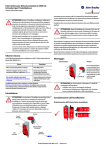
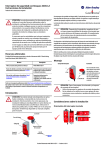
Installation and Operating Instructions
Safety interlocking switch with solenoid lock
Intended use
PSEN me1 safety switches are interlocking devices equipped with a solenoid operated guard lock. When used together with a suitable machine
control system these switches also monitor the position of movable guards. When correctly installed the PSEN me1 ensures that movable machine
guards can only be opened when it is safe to do so. Machine start-up, which could cause hazardous situations, is only possible if the movable
machine guards are duly closed and the PSEN me1 locking device is latched in position.
Standards governing installation and operation: EN 954-1 safety-related parts of control systems
EN 1088 interlocking devices with and without movable machinery guards
EN 60 204-1 electrical equipment of industrial machinery
Risk assessment at the machine acc. to:
EN 954-1 safety-related parts of control systems
EN 1050 safety of machinery, risk assessment
The mounting position is flexible, however the position should: 1- Allow authorized personnel to access the manual lock over-ride in order to control
and, if necessary, exchange components. 2- Ensure that foreign objects cannot enter the actuator opening whilst the guard is open.
Sequence of installation:
Installation by trained and qualified personnel only!
1. Select actuator head alignment
approach direction / 4 x 90° rotation / secured with single-way screw)
Approach direction
Horizontal H
Conversion
2.
1.
Vertical V
3.
Remove
cross head
screw
2.
4x90°
3.
1.
Secured with oneway screw
Max. 0.9 Nm
max. 0.9 Nm
Tamperproof
safety!
Replace cross
head screw with the
supplied one-way
screw.
Excess of the maximum torque of 0.9 Nm or installing the actuator so that it is subject to lateral forces may
damage the actuating mechanism of the switch gear. This can render the personal protection function useless
and cause serious injury or accidental death. Never use the safety switch and actuator as an end stop!
Date of issue: 22.02.2006 / Page 7 of 12
Document : 0800000458 / Version: 01 / 2196-06
Pilz GmbH & Co. KG, Sichere Automation, Felix-Wankel-Straße 2, D-73760 Ostfildern, Deutschland
Phone: +49 711 3409-0, Fax: +49 711 3409-133, E-Mail: [email protected], www.pilz.com
Template : 0850174292 Orig. 2
Installation and Operating Instructions
Actuator 1AS
(Standard)
28.1
23.5
63+4
Use ∅12 washers
for M4 screws
(ISO7093/DIN
9021) for form-fit
installation.!
Approach direction H
2.1 Securely fasten switching device; see illustrations for dimensions (mounting surface must be flat and plane).
2.2 Slide actuator into housing until the upper edge of the actuator is flush with the edge of the housing.
Align the actuator with the machine guard so that opening or closing the machine guard does not
apply lateral force to the actuator head. Verify by opening and closing the guards several times.
2.3 Permanently mount the actuator to the machine guard using rivets or single-way screws.
Approach
direction V
55
Socket-head
screw DIN912,
size 2.5
28.1
Approach
direction V
Approach
direction H
Actuator 1AR
(Universal)
In order to maintain the maximum level of safety, always order and use actuators together with the correct safety switches.
Actuator 1AS
R min > 400 mm
Actuator 1AR
R min > 150 mm
Actuator 1AR:
Change of mounting flange only prior to installation
Date of issue: 22.02.2006 / Page 8 of 12
Document : 0800000458 / Version: 01 / 2196-06
Pilz GmbH & Co. KG, Sichere Automation, Felix-Wankel-Straße 2, D-73760 Ostfildern, Deutschland
Phone: +49 711 3409-0, Fax: +49 711 3409-133, E-Mail: [email protected], www.pilz.com
Template : 0850174292 Orig. 2
Installation and Operating Instructions
Mechanical data
Enclosure
thermoplastic glass fibre reinforced
Mechanical life
1 million switching cycles at
(UL94-VO)
Cover
max. 600 cycles/hour
thermoplastic glass fibre reinforced
Mounting
4 M 5 screws
ISO1207
(UL94-VO)
Actuator head
ISO 4762
thermoplastic glass fibre reinforced
Tightening torque (max.)
and Zn-GD
Conductor cross-section
Separate actuator
St/PA / Zn-GD
Termination
Ambient air temperature
-25 °C to +70 °C, -13 °F to +158 °F
Cable entry
3 (M20X1.5)
Locking force FZh
max. 1500 N
Mounting position
any orientation
According to GS-ET-19
Weight
approx. 0.3 kg (w/o actuator)
Actuating force
27 N min.
Actuating speed
V=0.5 m/s max.
M= 2 Nm
cage clamp
1.5 mm² flex max.
Electrical connection
I
The electrical connection shall only be carried out
by trained and qualified personnel!
2
45
I Release snap-shut terminal lid with a screwdriver
II Screw cable gland into the chosen entry, this will
‘break-out’ blind hole, remove plastic disk.
1
Connecting to cage clamp terminals:
1) Insert screwdriver (blade width 2.5 mm) in
lower opening
2) Turn 45°
I
3) Insert flex. cable in upper opening
2
(Max. 1.5 mm cross-section)
remove screwdriver.
III Snap terminal chamber lid shut
Electrical data
Protection class
IP 67 acc. to IEC 60529
Approvals
see label on housing
Switch function
4 slow-action contacts max.
BG (GS-ET-19) (applied for)
Rated insulation voltage
Ui 250V
cCSAus B300, R300 (applied for)
Utilization category
AC 15 230V/2.5 A
Conventional thermal current
Ithe 2.5 A
Max. making current (4 contacts)
10 A
VDE 0660 T200, EN 60947-5-1
Type of short-circuit protection
4 A gl
IEC 60947-5-1
GS-ET-19
15 VA (0.5 s)
inrush
≤ 1.4 VA (24 V)
continuous
56 VA (0.2 s)
inrush
1.1 VA
continuous
Standards
VDE 0660 T100, EN 60947-1
Solenoid
Actuating cycles permanent
Operating voltage
600 / hour
PSEN me1
24 V AC/DC
PSEN me1.1
24 V DC +24/110/230 V AC
ON period
100 % duty cycle (to E1, E2)
Temperature class
B (130 °C), (266 °F)
Solenoid power consumption PSEN me1
PSEN me1.1
Date of issue: 22.02.2006 / Page 9 of 12
Document : 0800000458 / Version: 01 / 2196-06
Pilz GmbH & Co. KG, Sichere Automation, Felix-Wankel-Straße 2, D-73760 Ostfildern, Deutschland
Phone: +49 711 3409-0, Fax: +49 711 3409-133, E-Mail: [email protected], www.pilz.com
Template : 0850174292 Orig. 2
Installation and Operating Instructions
I
II
III
Actuator inserted and locked
( guard closed and locked )
Actuator inserted and unlocked
( guard closed but unlocked )
Actuator withdrawn
( guard open )
Switching function safety guard
Switching function locking device (solenoid)
PSEN me1S
PSEN me1.1S
Locking principle : Spring lock (without power)
The safety guard is automatically locked when the actuator is correctly inserted. Supplying power to the solenoid unlocks the protective system
and the safety guard can then be opened.
PSEN me1M
Locking principle : magnetic force (With power applied)
The locking device is only activated when power is applied to the solenoid. NB. If there is a power failure or there is a trigger error, the safety guard
can be opened.
Standard circuit
PSEN me1
Manual lock override
PSEN me1S
PSEN me1.1S
1.
Loosen locking screw.
2.
Rotate over-ride cam 90° with Allen key.
The actuator can now be withdrawn.
3.
E2 : Neutral N
Control
contacts
E1: Operating voltage L+
Rotate over-ride cam back to original position.
Screw and tighten locking screw and seal with sealing
lacquer. ( M = 0.5 Nm)
The manual lock over-ride should only be used with a 3mm socket
screw key if the guard locking device fails.
The access point shall be sealed after installation.
( e.g. with sealing lacquer)
Date of issue: 22.02.2006 / Page 10 of 12
Document : 0800000458 / Version: 01 / 2196-06
Pilz GmbH & Co. KG, Sichere Automation, Felix-Wankel-Straße 2, D-73760 Ostfildern, Deutschland
Phone: +49 711 3409-0, Fax: +49 711 3409-133, E-Mail: [email protected], www.pilz.com
Template : 0850174292 Orig. 2
Installation and Operating Instructions
System description / Suggested application
When the machine guard is closed, the actuator is engaged and locked in the safety switch. In this state the safety outputs in
the safety control module are closed and the contact in the control module (for the solenoid) is open - the machine can now
operate.
In order to carry out maintenance work behind the safety guard the operator has to switch off the machine. This will cause
opening of the outputs of the control module and shutoff of the machines power line. As the dangerous movement of the
machine may not stop immediately, the safety switch lock should only release the actuator after the machine has come to a
complete stop. A suitable control module, e.g. a lost-motion monitor or a delay module (safety timer) can be used for that
purpose.
The safety contacts (force disconnected N.C.) inhibit the machine from restarting whilst the machine guard is open. The
additional N.O. contacts can be used as signaling contacts, they do not have a safety function and are normally used for
indication only. These functions do not conduce safety, just availability of machinery. When used in conjunction with suitable
control modules the NO contacts may be used only for additional verification of the safety circuit.
The set of contacts monitoring the safety guard is form-fit driven by the actuator, so that the position of the safety guard is
directly monitored. The set of contacts monitoring the locking device has a positive drive connection to the lock. Thus ensures
that any failure of the locking device will be immediately detected by the safety control system. An integrated mechanical
mechanism ensures that the lock cannot be engaged whilst the actuator is removed from the safety switch.
The safety switch PSEN me1 can be applied in combination with other safety switching devices and safety control modules in
systems up to control category 4 acc. to DIN EN 954-1 when the applicable standards are maintained.
Maintenance / Inspection
The switching device is
maintenance-free. For trouble-free
operation and a long service life
the device should be inspected
regularly. Ensure that:
- all components are secure and tight
- switching functions operate properly
- all sealing gaskets are in proper
condition
- the components show no signs
of tear and wear.
Control voltage
Control contact
Actuator
contacts
(guard position)
Solenoid contacts
(guard locking)
If defects are the detected the
complete switching device and the
actuator have to be replaced.
Liability disclaimer
By breach of the given instructions
(concerning the intended use, the
safety instructions, the installation
and connection through qualified
personnel and the testing of the
safety function) any liability
expires.
- actuator inserted and locked
- solenoid un-energised
analysing
module
control
module
Contact assignment
illustrated for standard type :
PSEN me1S/1AS
570000
Hazardous machinery
Date of issue: 22.02.2006 / Page 11 of 12
Document : 0800000458 / Version: 01 / 2196-06
Pilz GmbH & Co. KG, Sichere Automation, Felix-Wankel-Straße 2, D-73760 Ostfildern, Deutschland
Phone: +49 711 3409-0, Fax: +49 711 3409-133, E-Mail: [email protected], www.pilz.com
Template : 0850174292 Orig. 2
Installation and Operating Instructions
Date of issue: 22.02.2006 / Page 12 of 12
Document : 0800000458 / Version: 01 / 2196-06
Pilz GmbH & Co. KG, Sichere Automation, Felix-Wankel-Straße 2, D-73760 Ostfildern, Deutschland
Phone: +49 711 3409-0, Fax: +49 711 3409-133, E-Mail: [email protected], www.pilz.com
Template : 0850174292 Orig. 2