1
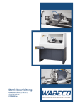
Operating Instructions CNC lathe With slant bed CC-D6200 hs Please read before putting into operation for the first time! Every person that operates the machine, maintains or repairs it, must have read the operating instructions, and in particular, the safety notes prior to putting the machine into operation. Please store these documents for subsequent use Original version in German/translation in English Status at 04/2015 Dear Customer! With the purchase of the WABECO machine you have decided in favour of a quality tool. This machine has been manufactured with the greatest of care and subject to precise quality controls. These operating instructions are designed to help you to use your new machine safely and correctly. For this reason, we ask you to read the appropriate notes through attentively and to take care to observe them. After unpacking the tool, check whether any transportation damages have occurred. Complaints, whatever their nature, should be communicated immediately. Subsequent claims cannot be recognised. For all queries and replacement part orders, please always specify the machine number (see type plate). Reprinting and reproductions of any kind, even extracts, require the written permission of WABECO Disposing of the machine The transportation and protective packaging is made of the following materials: ■ Corrugated card ■ Polystyrene without Freon ■ Polyethylene foil ■ Timber as single-use pallet (untreated) ■ Euro pallet (multiple use packaging) If you no longer need the items, or you do not want to reuse them, dispose of these items at the officially recognised recycling points. The machine is manufactured in such a way that 98% of the used materials that can be recycled, for example, steel, cast iron, aluminium and only 2% are chemical materials, e.g. cable sleeves of electrical cables, PCBs. If you have any difficulties in disposing of these parts properly, we would be happy to help: with prior agreement we will take back the machine in full and dispose of it. You must, however, cover the costs of sending it to us. wabeco-rs.de Walter Blombach GmbH 42899 Remscheid Am Blaffertsberg 13 Germany 2 Tel. +49 (0)2191 597-0 Fax +49 (0)2191 597-40 E-Mail [email protected] Contents Declaration of conformity CC-D6200 hs 5 1. Important safety notes 6 1.1 Intended use 6 1.2 Improper and incorrect use 6 1.3 Modifications to the machine 6 1.4 Safety regulations for proper use 6 1.5 Safety features 1.6 Explanations of the symbols 10 2. Delivery and set up 10 2.1 Transporting the machine 11 2.2 Setting up 12 3. Putting into operation 13 3.1 Setting up and connecting the control computer 13 4. Specifications regarding the machine 14 4.1 Identification of the model 14 4.2 Noise emission declaration 14 4.3 Technical data 15 4.4 Dimensions 17 4.5 Revolution selection 18 4.6 Electrical equipment 19 5. Set up tools 20 5.1 Set work piece zero point 20 6. Coolant system 21 6.1 Safety regulations for the handling of cooling lubricant 21 6.2 Filling the coolant system 21 6.3 Operating the coolant system 22 6.4 Positioning the segmented coolant hose 22 6.5 Controlling the flow of coolant using the coolant shut-off valve 23 7. Maintenance 24 8. Lubrication of the machine 24 9. Readjusting the main spindle 26 10. Overload coupling 27 11. Tool skid 27 12. Tailstock 29 13. 3 and 4 jaw lathe chuck 30 14. Operational faults and the elimination of such 31 15. Operating elements 9 33 3 Contents 16. Drawings and legends 34 16.1 Headstock with motor 34 16.2 Bed with lead screw 36 16.3 Transverse skid with lock plate 38 16.4 Tailstock 40 16.5 CNC drive X-axis 42 16.6 Speed sensor 43 16.7 CNC 8-fold tool changer 44 16.8 Safety cabin hood 46 16.9 Safety cabin interior 47 16.10 Operating console 48 16.11 Bracket arm for operating console 50 16.12 Axis motor and rotary encoder 51 17. Circuit diagram 52 17.1 Overall connection diagram 52 17.2 Axis motor and rotary encoder 53 18. Camlock main spindle (optional) 54 18.1 Undoing a chuck or holding flange from the camlock 54 Main spindle lug 18.2 Blocking a chuck or holding flange on the camlock Main spindle lug 4 54 Declaration of conformity We hereby declare, in the name of the manufacturer Walter Blombach GmbH Tool and machine factory with registered office in Remscheid and Neuerburg D-42871 Remscheid D-54673 Neuerburg P O Box 12 01 61 WABECO Str. 1-10 Phone: (02191) 597-0 Phone: (06564) 9697-0 Fax: (02191) 597-40 Fax: (06564) 9697-25 that the following named CNC lathe Type: CC-D6200 hs in the serial version, meets the following relevant regulations - EU Machine Directive 2006/42/EC - EMC Directive 2004/108/EC - EU Low Voltage Directive 2006/95/EC In order to fulfil/implement the requirements of the directives named above, the already published and applicable standards were drawn upon: EN ISO 12100:2010 DIN EN 60204-1:2006 EN ISO 23125:2010 Proxy for the compilation of the technical documentation is the operational head of the above named manufacturer, Mr Christoph Schneider. D-54673 Neuerburg 2015 ________________________________ Place and date of issue Betriebsleiter Christoph Schneider 5 1. Important safety notes 1.1 Intended use The lathes described in these operating instructions are designed for the processing of metal, plastic and timber only. To ensure safe operation of the lathes, the regulations set out in the chapter: "Safety regulations" must be observed. 1.2 Improper and incorrect use The lathes described in these operating instructions have been developed and manufactured for the purpose named above. Walter Blombach GmbH accepts no responsibility for property damage and personal injury caused as a result of not intended and incorrect use of the lathes. 1.3 Modifications to the machine For reasons of safety, it is forbidden for the user to make modifications of any type to the lathe. Walter Blombach GmbH accepts no responsibility for property damage and personal injury caused as a result of any modifications to the lathe by the user that have not expressly been authorised by the company. 1.4 Safety regulations for proper use The machine may represent a source of danger if it is not used correctly. For this reason, it is important that the following safety regulations are read attentively and observed carefully. Every person that operates the machine, maintains or repairs it, must have read the operating instructions, and in particular, the safety notes prior to putting the machine into operation. In order to fulfil these requirements, these operating instructions must accompany the machine throughout its entire lifetime and be available for research. In the event that the machine changes owners, the operating instructions must thus be passed on to the new owner along with the machine. 6 1. Important safety notes 1.4 Safety regulations for proper use Only spcedially trained persons may operate the machine. The guarantee and warranty are voided if damages are caused by improper operation. 1. We remind you that no liability will be accepted for damages caused by not observing these operating instructions. 2. The operator of the machine is to ensure that at least one copy of the operating instructions is stored in the immediate vicinity of the machine and available to the people who work with the machine. 3. The operator is to ensure that the safety and danger notifications on the machine are observed and that the signs are kept in a legible state. 4. Do not work without goggles. 5. Wear close fitting clothing and, if you have long hair, wear a hair net. Do not wear loose fitting or loose items (ties, shirt sleeves, jewellery etc.). 6. Gloves may not be worn. 7. In the event of an emission noise level as of 80 dB (A) at the workplace, ear defenders must be worn. 8. The machine may not operate without supervision. 9. Secure your machine in such a way that it cannot be switched on by children. Persons who have not been trained may not operate the machine. 10. Before using the machine, make sure it is in good working condition. Pay special attention to any damage to the grounded plug or the electrical connections. Never operate the machine with a defective, crushed or exposed cable. 11. Plug the grounded plug into a suitable socket for the machine. The cable for the machine may only be connected to a safety socket or a connection box. Have the safety socket or connection box checked by an electrical specialist before hand. 12. The safety socket or connection box must be close enough to the machine that the power cable is not under strain. 13. When carrying out maintenance and cleaning work, the machine must be switched off and the grounded plug pulled out. 14. Set-up work is only to be carried out with the machine switched off. 15. Do not reach into the operating machine. 16. Always switch the machine off when you are not using it. 17. Remain with the machine until it has come to a standstill. 7 1. Important safety notes 1.4 Safety regulations for proper use 18. Only have repairs carried out by a qualified specialist! Repair work may only be carried out by persons who are qualified for the relevant repairs and who are familiar with the appropriate health and safety requirements. 19. Protect the machine from damp. 20. Constantly check the machine for damages. Replace damaged parts only with original parts and have these replaced by a specialist. The guarantee and warranty is voided if accessories and replacement parts are use that are not designed for the machine. 21. Do not remove the generated shavings with your hand. Use the appropriate tools (handheld sweeper, hook, brush). 22. Tools and work pieces may never be changed when the machine is running. 23. Do not brake work pieces and bush using your hand or another object. 24. Never leave the chuck key fitted (even when not in operation). 25. Pay attention to the spread of the lathe chuck. 26. The maximum revolution range specified on the lathe chuck may not be exceeded. 27. Always keep safety door to motor closed 28. The safety door to motor may only be opened by trained personnel with a special key by unplugged safety contact pug 29. Turning steels must be firmly tensioned, at the correct height and as short as possible. 30. Do not measure at the rotating work piece (risk of accident, measuring tools will be damaged). 31. When working between the tips, check the locking lever of the tailstock for firm seating. 32. When working with the automatic feed, always pay attention to ensure that the tool skid does not come up against the lathe chuck or the tailstock. 8 1. Important safety notes 1.5 Safety features In order to enable you to work safely with our machines, we have incorporated the following safety mechanisms. These meet the relevant European safety requirements. ■ Safety cabin In order fort he machine to operate in CNC mode, the door to the safety cabin must be closed. ■ ON/OFF switch with under-voltage trigger The ON/OFF switch is fitted with an under-voltage trigger, thus, in the event of a power failure, the machine does not switch itself back on automatically. This prevents risks caused by the unexpected motion of the spindle. ■ Emergency off switch The emergency off switch acts to quickly stop the machine ■ Overload protection The machine is fitted with an overload protection feature. This overload protection feature switches the main drive motor off automatically when the machine is overloaded. The machine can only then be switched on after a waiting period. ■ Switch for operating modes (only for CNC machines) The mode switch has 3 settings (CNC mode – Idle position – Manual mode) that can only be selected with a key. After selecting the mode, the key can be removed in order to prevent a switching of the mode type by unauthorised persons. Working in CNC mode is only possible when door is closed. The door is locked as soon as the main spindle starts. If the door is open, the main spindle cannot be started. Working in set-up mode can be executed while the door is open. The switch for operating modes has to be set to set-up mode. The main spindle can be activated by closed as well as open door. 9 1. Important safety notes 1.6 Explanations of the symbols With an emission noise level as of 80 dB (A) at the workplace ear defenders must be worn Caution: Always pull the power plug prior to any maintenance work! Read the operating instructions prior to initial operation or maintenance work! Caution: Dangerous electric voltage! 2. Delivery and set up The machine is packed with care at the factory. The following should be checked after delivery: 1. Whether the packaging shows damages to be reported or 2. Whether the machine shows transportation damages to be reported If this is the case, we ask you to communicate this information immediately. Subsequent claims cannot be recognised. The machine must be set up on a suitable, even and firm surface. Suitable surfaces are, for example: ■ A tool cabinet (available optionally) ■ A separate workbench with a level surface (spirit level) that is strong enough to carry the weight of the lathe without bending. ■ A steel plate with a level surface (spirit level) The machine must be screwed securely to the surface it is set up on. There are holes in the base of the machine that are designed for this purpose. Good working results and low-vibration operation can only be ensured when the prerequisites for fixture as set out above are maintained. 10 2. Delivery and set up The place of set-up should be selected in such a way that ■ there is sufficient lighting ■ the electrical supply cable with socket outlet with earthing contact and 0-conductor is installed close enough to the machine that the supply line is not subjected to any tensile load. The machine has to be screwed to the installation surface and/or provided with a safe stand by using level elements. For this purpose, the base cabinet of the machine has four fixation thread bores (M10) as well as four fixation bores (Ø 12.5 mm). The doors of the safety cabin can only be opened if the machine is switched to operation modes CNC or set-up if the main spindle is not moving. 2.1 Transport of machine To transport the machine it is advisable to lift it at the lower cabinet with a forklift or platform trolley at the base cupboard of the safety cabin and carefully move it to the desired location. For this purpose, use wide forks (max. 1260 mm). We recommend using an intermediate plate for optimal load distribution and the protection of the machine. For example, a Euro-pallet of 1200 x 800 mm is suitable. . 11 2. Delivery and installation 2.2 Installation The appropriate bores for the installation of the safety cabinet onto a WABECO machining tool cabinet are already provided. The machining tool cabinet ensures secure positioning of the lathe and/or safety cabin. If the safety cabin is installed on another suitable installation surface, the 8 through-bores have to be drilled in the customers installation surface. The positions of the 8 fixation threads (thread M8) of the safety cabin are illustrated below. The diameter of the through-bores in the installation surface has to be at least 9 mm. The hexagon bolts (M10) included in the scope of delivery of the base cabinet can be used for adjustments. For this purpose, first screw the hex nut (M10), which are also included in the scope of delivery, to the hex bolts. Subsequently, insert the screws equipped with nuts into the four provided threads from below in the base cabinet. The base cabinet can now be adjusted by tightening or loosening the screw. Once the base cabinet is adjusted, you can counter the hexagon bolts with the nuts on the screws to secure their position. Good work results and low vibration running are only possible if the above-mentioned prerequisites for mounting are complied with. 12 3. ■ Putting into operation Use a dry cloth to remove the corrosion protection that was applied to all exposed parts for transport ■ In the event of marine impregnation of exposed parts, it is recommended you spray them with oil, allow it to work, and then remove the impregnation with a dry cloth ■ Once set up properly (see the section on delivery and set up) connect the grounded plug directly to a safety socket and the 230 V 50/60 Hz (optional 110 V 60 Hz) mains power supply ■ Provision of sufficient coolant for the operation of a coolant system. ■ Check all electronic operating elements, for example, ON/OFF switch, emergency off switch, potentiometer, bush protection hood, etc. for functionality ■ 3.1 When putting CNC machines into operation for the first time, always read the start-up manual Setting up and connecting the control computer When selecting a suitable control computer, pay attention to the system prerequisites of the control software. These are listed on the rear of the CD case sent with the machine. Follow the instructions in the start manual of the software to install the control software on the computer. The start manual can be found in the CD case of the control software included with the machine. In the next step, the software must be adapted to your machine. To do this, follow the instructions sent with the machine which detail the editing of the parameters. When the software has been successfully installed on the control computer and all parameters have been adapted successfully, the control computer must be connected with the machine controller. The machine controller communicates with the computer via the serial interface (COM port). In order to establish a connection between the machine controller and the computer, connect the end of the interface cable that is on the machine console to the COM port of the computer. CAUTION: The axis cable of the multiphase motors and the serial interface cable may only be plugged or unplugged with the control switched off. Otherwise damages to the control, the machine or the control computer may occur! 13 4. Information regarding the machine 4.1 Identification of the model The precise model designation of your machine can be found on the type plate attached to the machine. 4.2 Noise emission declaration Noise emission declaration in accordance with DIN EN ISO 3744 Emission values in idle Emission noise level at the workplace at 50 % = 68.0 dB (A at 100 % = 73.6 dB (A) Sound power level at 50 % = 77.8 dB (A) at 100 % = 82.3 dB (A) With an emission noise level as of 80 dB (A) at the workplace ear defenders must be worn 14 4. Specifications regarding the machine 4.3 Technical data Working areas Distance between centres 600 mm Centre height 135 mm turning-Ø above cross slide 170 mm Swing diameter via guide 270 mm Bed width 185 mm Main drive motor Nominal voltage Nominal frequency frequency controlled main drive motor 230 V, 50/60 Hz Spindle revolutions, infinite 230 V 50/60 Hz 2.0 kW 50 - 5000 rpm Machine accuracy Concentricity of the spindle lug 0,005 mm Cylindrical rotation on 100 mm overhung 0,01 mm Cylindrical rotation with simple turning on 300 mm between the centres 0,015 mm Headstock Main spindle aperture Ø 20 mm Taper in main spindle MK3 Main spindle lug According to DIN 6350 Tool skid Adjustability of the transverse skid 140 mm Adjustability of the longitudinal skid 60 mm Longitudinal skid can be swivelled by Max. turning steel height 360° 20 mm Tailstock with quick adjustment Lateral adjustability of the tailstock upper Tailstock sleeve ± 10 mm With inner Morse taper MK2 Sleeve adjustability 65 mm Scale ring read accuracy 0.1 mm Thread cutting Tumbler gear drive 2 automatic longitudinal feeds Change gear set for thread cutting For left-right thread 0.085 and 0.16 mm/revolution Metric 0.25 - 7.0 mm - imperial 10 - 40 G/" 15 4. Specifications regarding the machine 4.3 Technical data Positioning accuracy ± 0.015 mm Travel speed (fast mode) x and y axes 30 – 1,000 mm/min Toolchanger cross section for 4 external machining tool 10 x 10 mm location bore for 4 internal machining tools Ø 16 mm Safety cabin volume coolant feed pump 16 27 litre 230 Volt, 50/60 Hz 4. Specifications regarding the machine 4.4 Dimensions 17 4. Specifications regarding the machine 4.5 Revolution changer The potentiometer ((8) of the control panel) allows the infinite setting of the revolutions of the tool spindle from 50 to 4800 rpm (2. level = default setting). In order for the revolutions to be activated correctly via software, the potentiometer must be set to 100%. During the operation, it can be used to minimally adjust the revolution according to the processing conditions. If the lower revolutions of 50-2500 rpm (1st setting) are required, the drive belt must be applied. To do this, proceed as follows: 1. Open the gear cover hood by undoing the safety screw with the supplied special key. 2. Release the four hexagon nuts (5); this allows the sliding of the clamping sled (4) of the motor. 3. Slide the clamping sled incl. motor toward the machine; this loosens the belt tension and the belt can be relocated. 4. Place the drive belt (2) onto the otertransmission oft he belt disks (1+3). (Small diameter at motor, large diameter at main spindle.) 5. Pull the clamping sled (4) of the motor away from machine to tension the drive belt (2) and refasten the four hexagon nuts (5). 6. Close the protective drive door and secure with both safety screws. 18 4. Specifications regarding the machine 4.5 Revolution changer The following table illustrates the torque of the work spindle depending on the selected gear level and setting of the potentiometer. Setting on the potentiometer 1st setting rpm 2nd setting rpm 0% 50 100 10% 200 370 20% 470 900 30% 725 1400 40% 970 1900 50% 1225 2400 60% 1470 2900 70% 1725 3400 80% 2000 4000 90% 2280 4500 100% 2500 4800 4. Specifications regarding the machine 4.6 Electrical equipment The frequency-regulated main drive motor is delivered already installed ■ the under-voltage trigger is integrated in the electronics of the motor ■ The ON/OFF switch has to be switched on again also after an interruption of power ■ In the event of the main drive motor being overloaded, it will switch itself off automatically. ■ The main drive motor can only be switched back on again after a short waiting period ■ For this purpose, first switch the machine off via the ON/OFF switch; wait 5 seconds and reactivate. 19 5. Set up tools First, the correction values for all 8 tools have to be set to 0.00 in the tool memory in X and Z. (Parameter CAM tool memory) Tool 1 is the 0-tool, The adjusted amounts are here generally maintained at X 0 and Z 0. ■ Run machine reference ■ Select tool T1 to random diameter in X and run to beginning of workpiece in Z. (if required, clamp turned part and turn splint) Leave X-axis at turned diameter in X and set Z-axis to beginning of workpiece. Here, work piece zero point sets keyboard combination (Ctrl X) (Ctrl Z) (Position display = X 0.00 Z 0.00) ■ Select tool T3 Move to same position in X and Z with tool T3 where zero was set previously with T1 (in X to turned diameter and in Z to workpiece starting point) ■ The new position value of X-axis is not X 0.00 at the turned diameter, but e.g. X 10.80 ■ Enter in tool memory at T3: New position value in X Radius is / 2 = 10.80 = 5.40 Adjusted amount in X = 5.40 ■ The new position value of display Z-axis at start of work piece is e.g. Z – 8.00 Enter at T3 in tool memory: New position value in Z = = - 8.00 Adjusted amount in Z 5.1 = - 8.00 Set workpiece zero point Select T1 Drive with workpiece T1 to turned diameter in X-axis. (Position display in X-axis = 0.00) Measured turned diameter = e.g. 15.20 Now enter the required zero floating for X- axis in direct entry field. G54 X- 15.20 (Enter) New value in position display = X 15.20 20 6. Coolant system 6.1 Safety regulations for the handling of cooling lubricant 1. Pay particular attention to leaked coolant as this can quickly cause people to slip and caused accidents as a result. 2. Secure your coolant system in such a way that it cannot be switched on by children. Persons who have not been trained may not operate the coolant system. 3. Ensure you have a clean workplace, dirty areas can quickly lead to accidents. 4. Never use the coolant system when processing magnesium alloys. In combination with watermixed coolants, this may result in flammable gas mixtures which may explode under certain circumstances. 5. Avoid longer skin contact with the coolant. 6. Use skin protecting creams when handling coolants. 7. Regularly monitor the concentration of the water-mixed coolant. 8. Regularly monitor the pH value of the coolant. 9. Make sure that the coolant is only disposed of in an environmentally friendly way in accordance with the relevant guidelines. Coolant is a special waste product. 6.2 Filling the coolant system A number of protective measures must be observed and taken in order to ensure that the handling of coolant does not cause health risks or environmental loads. ■ Always observe the datasheet and the safety regulations of the coolant being used (can be obtained from the supplier or manufacturer) ■ Observe all safety regulations set out in these operating instructions, in particular those that refer to the safe handling of coolants. ■ In order to ensure reliable operation of the coolant pump, a minimum coolant filling level is required in the coolant tank. ■ The capacity of the coolant system is approximately 19 litres. ■ The maximum filling level should be just below the shelf insert ■ The minimum filling level is approximately 15 mm below that. ■ To fill, remove the shelf insert and fill to the maximum filling level with a suitable coolant whilst observing all safety regulations. ■ After filling, replace the shelf insert 21 6. Coolant system 6.3 Operating the coolant system (4) Switch for coolant pump Switch position ( 0 ) Pump switched off Switch position ( I ) Pump switched on (Caution: Coolant flow is controlled with the coolant shut-off valve) 6.4 Positioning the segmented coolant hose The flexible segmented hose (shown in blue) is made up of individually adjustable elements and can be shaped by hand or set as required. The segmented hose and the nozzle are to be positioned in such a way that the coolant flows as directly as possible onto the blade of the cutting tool of the lathe. Attention should be paid to ensure that the nozzle does not come into contact with the cutting tool. 22 6. Coolant system 6.5 Positioning the segmented coolant hose Coolant shut-off valve in the "open" position Maximum coolant flow Rotation of the coolant shut-off valve clockwise Flow is reduced Coolant shut-off valve in the "closed" position Coolant flow stopped 23 7. Maintenance A long lifetime of the machine will depend on the appropriate care and maintenance. ■ All maintenance and repair tasks may only be carried out with the grounded plug pulled. ■ The machine must be cleaned after each use. ■ If the machine is set up in a wet room, all exposed parts must be oiled after each use to prevent corrosion. ■ Always lubricate all moving parts well. ■ In the event of bearing or skid play, immediately adjust in order to prevent it from destroying the bearing or skid guide. Approximately every 100 operating hours ■ Check the tension of the poly V and gear belt and adjust if necessary. ■ Check the play in the guides and feed spindles and set if necessary. 8. Lubrication of the machine The lubrication process: ■ Reduces wear and friction ■ Increases the lifetime ■ The metal surface are protected from corrosion We recommend: ■ A class 2NLGI multi-purpose grease for lubrication ■ A lubrication oil with a viscosity of 100 mm 2/s for oiling The lathe is to be lubricated every 8 hours of operation in accordance with the lubrication plan. The lubrication points. ■ Bed guide ■ Dovetail guide cross slide ■ Dovetail guide traverse slide ■ Tailstock sleeve Are lubricated with the help of an oil can and an ordinary lubrication oil by moving the skid or sleeve backwards and forwards. All other lubrication points are lubricated with a grease press at the designated lubrication nipples. 24 1 Every 8 hours of operation 2 Every 8 hours of operation 8. Lubrication oft he machine 25 9. Readjusting the main spindle The headstock is screwed to the lathe bed. The headstock contains the main spindle with two adjustable precision tapered roller bearings. If adjustment is required, proceed as follows: 1. Open the gear cover hood by undoing the safety screw with the supplied special key 2. Undo the stud screw (1) in the setting nut (2) 3. The setting nut (2) is located at the rear end of the main spindle 4. Rotate the setting nut (2) clockwise until the bearings run free again (it must be possible to rotate the main spindle by hand easily) 5. Tighten the stud screw (1) back up again 6. If the tapered roller bearings are set too tightly they will quickly become unusable 7. Close the gear cover hood by tightening the safety screw with the supplied special key 26 10. Readjustment of the bearing clearance of the lead screw On the right side, the lead screw is axial mounted. This mount enables the lead screw (1) to be set without play. If adjustment to the mount is required, please proceed as follows 1. Undo the threaded pin (4) 2. Turn the setting nut (3) clockwise against the ball bearing (2) until the lead screw (1) has no more axial play 3. Then tighten the threaded pin (4) securely 11. Tool skid The tool skid is positioned, at the front, on a prismatic guide and, at the rear, on a flat guide. The skid is held onto the bed from below with the guide bar (9) and can be set to without play using the setting bar (12). If adjustment to the setting bar (12) is required, please proceed as follows: 1. Undo the hexagonal nuts (11) 2. Using an Allen key, tighten the threaded pins (10) in such a way that the skid is still able to move easily. 3. After setting, tighten the hexagonal nuts (11) back up again 27 11. Tool slide The possibly occurring axial clearance of spindle (6) can be adjusted in spindle bearings. If adjustment is required, please proceed as follows: 1. Open cable conduit (1) far enough for the cable to pulled through easily. 2. Loosen the four screws (2) 3. Pull off hood (3) from motor support plate by simultaneous release of motor cable. 4. Release set screw (4) 5. Turn belt wheel (5) clockwise until there is no more axial clearance 6. Refasten set screw (4) 7. The spindle (6) has to turn easily after subsequent adjustment 8. Reassemble parts in reverse sequence after adjustment 28 12. Tailstock ■ The tailstock can be moved on the lathe bed. ■ By moving the clamping lever (3), the tailstock can easily be secured in any position. ■ The tailstock is made up of an upper and lower section. ■ The upper section can be moved by a maximum of ±10 mm in order to turn long, slim tapers. To do this, proceed as follows: 1. Undo the hexagonal nut (6) 2. With the help of both threaded pins (8), slide the upper section into the required direction ■ The central position of the tailstock is shown by the scale mark (7) ■ Turn a sample to see whether the work piece is cylindrical, correct the tailstock setting if necessary Tailstock sleeve ■ The solid tailstock sleeve has a millimetre scale. To read off the distance of travel of the tailstock sleeve, there is a scale ring (9) ■ One mark on the scale corresponds to an adjustment of 0.1 mm. ■ One turn of the ball crank (5) corresponds to a distance of 2 mm. ■ Centre point, drill or drill chucks are automatically ejected when turning back. Tool holder ■ There is an inside cone MK 2 which is designed to hold tools and is incorporated in the sleeve (1). ■ Tightening the clamping lever (2) ensures that the sleeve may be easily clamped in any position. ■ The sleeve is moved axially by the hand crank (5) by way of the threaded spindle (4). 29 13. 3 and 4 jaw lathe chuck The 3-jaw lathe chuck Is used to tension circular, three and six edged work piece centrally to the spindle axis. The 4-jaw lathe chuck Is used to tension square work pieces centrally to the spindle axis. Risk of accidents Do not attempt to clamp work pieces that are over the permitted clamping range. The clamping force is thus too low and the jaws may come undone The maximum revolution range specified on the lathe chuck may not be exceeded Mounting the jaws: 1. The jaws and guides are numbered from 1 - 3 or 1 – 4. 2. Open the lathe chuck with the key in such a way that the drilling jaws are released (sequence: 3, 2, 1 or 4, 3, 2, 1) 3. Insert turning jaw 1 into guide 1 4. Push turning jaw 1 in the direction of the chuck centre point and, at the same time, turn the chuck key clockwise 5. When the coil has caught turning jaw 1, insert turning jaw 2 into guide 2 6. Repeat the procedure with jaws 2, 3 and 4 (for a four jaw lathe chuck) 7. Then visually check the positions of the jaws. These must meet centrally Mounting the drilling jaws: 1. If you wish to use the drilling jaws again, the process is the repeated in the same order. 2. Three jaw lathe chuck: First jaw 1, then 2, then 3 3. Four jaw lathe chuck: First jaw 1, then 2, then 3, then 4 30 14. Operational faults and the elimination of such Operational faults Possible cause Remedy Machine cannot be switched on 230V voltage is not present Plug is not fitted correctly Check the fuse for the socket Main spindle motor no longer Emergency off switch not Unlock the emergency off unlocked switch Motor controller must be unlocked Wait approx. 5 seconds after starts after the unlocking of the unlocking the emergency emergency off switch ON/OFF switch before reactivating machine with ON/OFF switch. Also the manual operating field of the software has to be closed and the machine must be reloaded. Tool skid cannot be moved or Clamping of the tool skid is on Open the clamping considerable force Guide play is set too narrowly Adapt the guide play Transverse cannot be moved or Guide play is set too narrowly Adapt the guide play Wrong coolant set Check the mixing ratio of the can only be moved with can only be moved with considerable force Rust on work pieces of machine parts when using coolant coolant and correct if required lubrication (never cool with water alone!) Tool holder cannot be inserted An incorrect tool taper of the tool Only use the appropriate tool into the main spindle (reducing holder has been used in holders for the machine sleeve of the main spindle) combination with the reducing sleeve Inner cone of the reducing sleeve Clean the relevant cone or outer cone of the tool holder is contaminated Doors of the safety cabin cannot be opened Machine is not switched off and/or Machine switched of, switch switch for operating modes in zero for operating modes on CNC position operation of set-up mode Main spindle is running Main spindles stops 31 14. Operational faults and the elimination of such Operational faults Tool overheated Mögliche Ursache Abhilfemaßnahme Revolutions too high Reduce the revolutions Feed too high Reduce the feed Working without coolant Use coolant Insufficient coolant feed at the Align the coolant hose cutting edge correctly Tool blunt Sharpen tool or use a new tool Increased friction caused by Remove the shavings from the shaving build up in the tensioning hole more frequently groove of the tool (drilling work) (withdraw) Use a coated tool Wash the processing area with coolant Unsuitable tool chosen for the Only use the suitable tool for material to be processed the relevant material Tool cannot be removed from Tailstock sleeve is not fully Fully crank back the tailstock the tailstock sleeve cranked back sleeve to automatically eject tools with ejector lugs Use tool without ejector lugs Place a soft and sufficient wide inlay between the tool and tailstock front. Now crank the tailstock sleeve back to push the tool out. (Use of tools without ejector lugs is possible by screwing a suitable threaded pin into place which extends the length of the tool backwards) 32 15. Operating elements 1. Emergency off switch 2. Mode selection switch (CNC operation) (Idle position) (Set-up mode) 3. ON/OFF switch with low voltage trigger 4. Coolant ON/OFF 5. Switch not occupied (available for further functions) 6. Legend to diodes and reset switch 7. Diodes to display the status of the controller 8. Potentiometer rotating knob for speed selection of the electrical drive motor A plug (2) is located at the rear of the control panel which can be used to power a notebook or computer screen. The control panel contains a storage compartment (1) which can hold the notebook power pack and/or spare cables. If the machine alone is connected to a 16A secured socket, a user with a performance of max. 700W can be connected to the power plug (2) of the control panel. 33 16. Drawings and legends 16.1 Headstock with Motor 34 16. Drawings and legends 16.1 Headstock with motor Part No. Items Order No. Description 1 1 10600154 Spindle input 2 1 10600106 Main spindle 3 1 10600171 Parallel key 4 3 16191200006012 Screw 5 1 10600105 Oil scraper ring 6 1 10600104 Flange 7 2 51502109 Tapered roller bearing 8 2 51502517 Lubrication nipple 9 1 10600101 Headstock 10 1 10600104 Flange 11 3 16196500006012 Screw 12 1 51004055-0003 Bush with collar 13 1 10600137 Toothed wheel 14 1 51004055-0004 Sleeve 15 1 51006600-0001 Gear wheel 16 1 16091300006008 Threaded pin 17 1 10600140 Nut 18 1 51502300 Belt 19 1 1062800 Rotary encoder complete 20 4 16112500010000 Washer 21 4 16193300010050 Screw 22 1 23 1 16191200006020 Screw 24 1 16167980006000 Fanned washer 25 1 51004025-0024 Pressure washer 26 1 51006675-0001 Gear wheel motor 27 1 51500128-00041 Motor with pulley Headstock cover (contained in cabin) 35 16. Drawings and legends 16.2 Bed with lead screw 36 16. Drawings and legends 16.2 Bed with lead screw Part No. Items Order No. Description 1 1 10600601 Bed 2 3 16196500004008 Countersunk screw 3 1 51006555-0020 Sleeve 4 1 51502112 Ball bearing 5 1 51006555-0007 Bearing flange 6 1 10600602 Support bearings, front 7 4 16191200005016 Screw 8 1 51402152-0001 Cover lead spindle bearing 9 4 16191200005012 Screw 10 1 51505226 Ball screw with ball nut 11 1 51502656 Coupling 12 1 161705A0018000 Adjusting ring 13 1 51004040-0011 Feed shaft 14 1 51402150-0001 Motor bracket Z-axis 15 1 51502518 Lubrication nipple M5 16 1 51004050-0013 Toothed belt pulley 17 1 51502320 Gear belt 18 1 51004020-00022 Toothed belt pulley Z12 19 1 51402115-0001 Terminal box 20 2 16191200004030 Screw 21 1 51500706 Terminal clamp 22 1 51500122 Multiphase motor 23 1 24 1 10600616 Bearing cover 25 2 16191200003006 Screw 26 1 51002020-0004 Tailstock stopper 27 2 16191200005012 Screw 28 1 16091300006006 Threaded pin 29 1 51007250-0001 Push piece 30 1 51004035-0007 Setting nut 31 2 51502112 Ball bearing 32 1 10600615 Support bearing, rear 33 1 51502517 Lubrication nipple 34 2 16112500008001 Washer 35 2 16191200008025 Screw 36 1 51006940-0001 Support for CNC limit switch 37 1 51007250-0001 Push piece 38 1 16191200006010 Screw 39 1 51500633-0002 End switch 40 2 16191200004020 Screw Cover guide head stock (contained in cabin) 37 16. Drawings and legends 16.3 Cross slide with saddle apron 38 16. Drawings and legends 16.3 Cross slide with saddle apron Part No. Items Order No. Description 1 1 51007176-0001 Transverse skid, upper section 2 6 16063250005040 Cylinder pin 3 6 16091300006010 Threaded pin 4 6 16193400006000 Nut 5 1 51505210-0005 Ball screw spindle with ball screw nut 6 1 51004020-0014 Reducing bush 7 1 51502113 Ball bearing 8 1 106000316 Spindle bearing, transverse skid 9 2 16191200006020 Screw 10 1 51502113 Ball bearing 11 1 51004050-0001 Toothed belt wheel Z30 12 1 51007250-0001 Push piece 13 1 16091300006006 Threaded pin 14 1 51001017-0003 Adjustment bar 15 1 10600701 Transverse skid, lower section 16 2 10600390 Felt 17 2 10600388 Felt clamp 18 8 16191200004010 Screw 19 1 10600391 Setting bar 20 1 10600328 Guide bead 21 4 16193300008025 Screw 22 4 16091300006012 Threaded pin 23 8 16193400006000 Nut 24 2 10600383 Felt clamp 25 2 10600382 Felt 26 1 10600376 Guide bar 27 1 10600719 Ball-nut bracket 28 1 10600714 Lock plate 29 4 16091300006025 Threaded pin 30 1 51505226 Ball nut with ball spindle 31 4 16191200005020 Screw 32 1 16191200006012 Screw 33 1 106003417 Guide 34 3 16191200005016 Screw 35 1 51505210-0005 Ball nut with ball spindle 36 2 16191212012035 Screw 37 1 16191200008045 Screw 38 6 16191200005012 Screw 39 1 51006425-0001 Limit stop switch 40 1 51500633-0001 End switch 41 2 16191200004020 Screw 39 16. Drawings and legends 16.4 Tailstock 40 16. Drawings and legends 16.4 Tailstock Part No. Items Order No. Description 1 1 10600401 Tailstock upper section 2 1 10600402 Tailstock lower section 3 1 10600403 Clamping piece 4 1 10600404 Sleeve 5 1 51004020-0019 Spindle 6 1 51006550-0001 Flange 7 2 16191200005012 Screw 8 1 10600408 Scale ring 9 1 51502131 Steel ball 10 1 51502009 Pressure spring 11 1 51004045-0011 Dial 12 3 51007250-0001 Push piece 13 3 16091300006010 Threaded pin 14 1 16091500006016 Threaded pin 15 1 16193300010070 Screw 16 2 16191300008040 Threaded pin 17 1 16112500010000 Washer 18 1 16193400010000 Nut 19 1 10600419 Scale tape 20 2 51502517 Lubrication nipple 21 1 51507022-0001 Ball crank 22 1 16073430003018 Spiral tensioning pin 23 1 51507033 Tensioning lever 24 1 10600424 Sleeve clamping element, top 25 1 10600425 Sleeve clamping element, bottom 26 3 16193400010000 Nut 27 1 16091300010050 Stud bolt 28 1 10600428 Clamping bush 29 1 10600429 Scale 30 2 16191200003006 Screw 31 1 10600431 Clamping strap 32 1 10600432 Eccentric shaft 33 1 10600433 Washer 34 1 16073430003024 Spiral tensioning pin 35 1 10600435 Lever 36 1 10600436 Handle 41 16. Drawings and legends 16.5 CNC drive X-axis Part No. Items Order No. Description 1 1 51402151-0001 Motor cover 2 4 16191200004010 Screw 3 4 16112500004000 Washer 4 4 16191200005016 Screw 5 8 16112500005000 Washer 6 1 51500122 Motor 7 1 51004020-00022 CNC drive X-axis 8 1 51502321 Gear belt 9 2 51402153-0001 Bracket 10 4 16167980005000 Fanned washer 11 4 16193400005000 Nut 12 4 16191200005012 Screw 13 1 16191200006030 Screw 14 14 51006491-0001 Motor bracket 42 16. Drawings and legends 16.6 Speed sensor Part No. Items Order No. Description 1 1 51500101-0001 Speed sensor 2 1 51006575-0003 Holding flange 3 3 16196500004008 Screw 4 1 51502323 Gear belt 5 1 51004055-0004 Sleeve 6 1 51006555-0002 Toothed belt wheel Z32 7 1 51006555-0001 Toothed belt wheel Z32 8 2 16000002214020 Adjusting washer 9 1 16191300005006 Threaded pin 10 2 16191200004010 Screw 11 2 16112500004000 Washer 43 16. Drawings and legends 16.7 CNC 8-fold tool changer Part No. Items Order No. Description 1 1 51508480-00011 Basic body 2 1 3 4 16193300008020 Screw 4 1 51508480-00031 Bearing cover 5 3 16191200005020 Screw 6 3 16191200004010 Screw 7 4 51004025-0021 Capstan nut 8 2 51502118 Ball bearing 9 1 16047200032000 Securing ring 10 1 51004018-0003 Spacer ring 11 1 51508480-00021 Cover 12 4 16191200006060 Screw 13 1 1606885A040425 Parallel key 14 1 15 1 51502600-0001 Coupling 16 1 51500113 Motor 17 4 16191200004012 Screw 44 Base plate (contained in tool changer) Worm gear (contained in tool changer) 16. Drawings and legends 16.7 CNC 8-fold tool changer Part No. Items Order No. Description 18 1 51401812-0001 Cover hood 19 1 51501505 Counter nut 20 1 51501533 Cable screw 21 1 51502601 Worm gear 22 1 51508480-00051 Spacer 23 1 51508480-00041 Ratchet wheel 24 1 51004055-0001 Capstan nut 25 2 51502108 Tapered roller bearing 26 1 27 1 1606885A005020 Parallel key 28 1 6885A080818-01 Parallel key 29 1 51502199 Nilos ring 30 1 51508481 Tool carrier disc 31 4 16091300008010 Threaded pin 32 8 16091500008016 Threaded pin 33 4 16191200008025 Screw 34 4 160635250006020 Cylinder pin 35 1 Spacer disc (contained in tool changer) 36 1 Ratchet (contained in tool changer) 37 1 Bolt (contained in tool changer) 38 1 Bolt (contained in tool changer) 39 1 51502036 Tension spring 40 1 16191200005010 Screw 41 1 51502602 Worm gear 42 1 16091300006010 Threaded pin 43 4 16191200006020 Screw 44 3 51007250-0001 Push piece 45 3 16091300005006 Threaded pin Main spindle (contained in tool changer) 45 16. Drawings and legends 16.8 Safety cabin hood Part No. Items Order No. Description 1 1 51402020-0001 Cabin hood 2 2 Sliding door guide (included in cabin 51402020-0001) 3 1 4 1 51500642 Activator for safety switch Bracket activator (contained in cabin 51402020-0001) 5 1 51500638 Safety switch 6 2 51507006 Ball handle 7 1 51402030-0001 Sliding door, front 8 1 51402030-0002 Sliding door, rear 9 1 Drive-protection door (included in cabin 51402020-0001) 46 16. Drawings and legends 16.9 Safety cabin interior Part no. Item Order no. Description 1 1 Interior cabin (contained in cabin 51402020-0001) 2 2 Coolant tray (contained in cabin 51402020-0001) 3 1 Coolant tray, left (included in cabin 51402020-0001) 4 1 Coolant tray, pump (included in cabin 51402020-0001) 5 1 6 1 51000119-0007 Coolant pump Clamping slide motor (included in cabin 51402020-0001) 7 1 8 1 9 1 10 1 51401481-0001 Control box Control palatine nccad professional 51400485-0001 Protective plate spindle passage Cover plate bed, rear (included in cabin 51402020-0001) 11 1 Cover plate bed, front (included in cabin 51402020-0001) 47 16. Drawings and legends 16.10 Operating console 48 16. Drawings and legends 16.10 Operating console Part no. Item Order no. Description 1 1 51401485-0001 Operating console 2 1 16191200004025 Screw 3 1 51501304 Symbol for mass connection 4 1 51500624-0001 Emergency Off button complete 5 1 51500600 Turn switch 6 1 51500606 On-Off switch 7 2 51500601 Toggle switch 8 1 9 1 51500801-0001 Potentiometer 10 1 51500772 Power socket 11 4 16196500004009 Countersunk screw 12 2 16193400004000 Groove 13 2 16197980004000 Fanned washer 14 7 16179810003095 Screw LED's with switch (included in control packet) 49 16. Drawings and legends 16.11 Support arm for control panel Part no. Item Order no. Description 1 1 51002130-00041 Base plate with joint to support arm 2 1 51002416-00021 Square pipe with joints 3 2 51004020-0024 Guide bush to support arm 4 4 51004020-0010 Washer Ø20x8,1x3 5 2 16198500008000 Groove 6 2 16091300008030 Threaded pin 7 2 16193300008025 Screw 8 2 51507031 Clamping lever 9 2 16112500010000 Washer 10 2 16191200010030 Screw 50 16. Drawings and legends 16.12 Base cabinet (optional) Part no. Item Order no. Description 1 1 1120268 Base cabinet 2 1 Door (contained in Art.-No. 1120268) 3 1 Lock (contained in Art.-No. 1120268) 4 1 Door (contained in Art.-No. 1120268) 5 4 Hinge (contained in Art.-No. 1120268) 51 17. Circuit diagram 17.1 Overall connection diagram see legend for circuit diagrams 17.3 52 17. Circuit diagram 17.2 Axis motors and rotary encoders see legend for circuit diagrams 17.3 53 17. Curcuit diagram 17.3 Key for circuit diagram Color-code by IEC 60757 BK Black PK Pink BN Brown RD Red BU Blue VT Violet GN Green WH White GY Grey YE Yellow OG Orange YG Yellow/Green A2 Socket 230VAC B2 Machine lamp F1 Noise filter M2 Coolant pump M3 Fan for industrial screen M4 Axis motor 3H8221 - 624/6A, XYZ axis M5 Axis motor t-axis 103H7123-0740 3 ADC M8 Main spindle motor 2.0 KW, high-speed N1 Power plug N3 9- pin plug N4 Axle motor terminal block N5 15-pin, Sub-D plug P2 CNC control board PE Protection against electrical shock R2 10 kΩ (ohm) potentiometers spindle speed S1 Emergency switch-off S2 Main switch with low voltage trigger S3 Selection switch S4 Switch coolant S5 End switch safety cabin S7 End switch S8 Main switch with CNC control status display S9 Switch for machine lamp T3 Encoder for spindle revolutions T4 Lock for operator door with query X1-10 Cabling terminal block 54 20. Camlock main spindle (optional) 20.1 Undoing a chuck or holding flange from the camlock main spindle lug ■ Open the three clamping tappets (4) located around the circumference of the main spindle (1) using an Allen key in size 10 mm (not included in the scope of delivery). ■ After opening, the markings of the clamping tappets must, as shown, point to the markings on the main spindle. ■ The moving of the camlock bolt (2) and thus the removal of the chuck or holding flange is only possible if both markings point to one another. ■ Remove the chuck or the holding flange. 20.2 Blocking a chuck or holding flange on the camlock main spindle lug ■ Ensure that the markings on the clamping tappets (4) point to those markings on the main spindle (1). ■ Place the chuck or holding flange on the main spindle, in doing so, insert the camlock bolt (2) into the holes drilled in the main spindle. ■ Tighten the three clamping tappets (4) located around the circumference of the main spindle (1) using an Allen key in size 10 mm (not included in the scope of delivery), so that the chuck or holding flange pulls towards the main spindle. 55