1
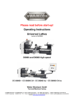
Operating Instructions Lathes With prismatic cast iron bed D4000 Bitte vor Inbetriebnahme lesen! Bitte vor Inbetriebnahme lesen! Please read before putting into operation for the first time! Every person that operates the machine, maintains or repairs it, must have read the operating instructions, and in particular, the safety notes prior to putting the machine into operation. Please store these documents for subsequent use Original version in German/translation in English Status at 10/2014 Dear Customer! With the purchase of the WABECO machine you have decided in favour of a quality tool. This machine has been manufactured with the greatest of care and subject to precise quality controls. These operating instructions are designed to help you to use your new machine safely and correctly. For this reason, we ask you to read the appropriate notes through attentively and to take care to observe them. After unpacking the tool, check whether any transportation damages have occurred. Complaints, whatever their nature, should be communicated immediately. Subsequent claims cannot be recognized. For all queries and replacement part orders, please always specify the machine number (see type plate). Reprinting and reproductions of any kind, even extracts, require the written permission of WABECO Disposing of the machine The transportation and protective packaging is made of the following materials: ■ Corrugated card ■ Polystyrene without Freon ■ Polyethylene foil ■ Timber as single-use pallet (untreated) ■ Euro pallet (multiple use packaging) If you no longer need the items, or you do not want to reuse them, dispose of these items at the officially recognized recycling points. The machine is manufactured in such a way that 98% of the used materials that can be recycled, for example, steel, cast iron, aluminium and only 2% are chemical materials, e.g. cable sleeves of electrical cables, PCBs. If you have any difficulties in disposing of these parts properly, we would be happy to help: with prior agreement we will take back the machine in full and dispose of it. You must, however, cover the costs of sending it to us. wabeco-rs.de Walter Blombach GmbH 42899 Remscheid Am Blaffertsberg 13 Germany 2 Tel. +49 (0)2191 597-0 Fax +49 (0)2191 597-40 E-Mail [email protected] Contents Declaration of conformity for D4000 6 1. Important safety notes 7 1.1 Intended use 7 1.2 Improper and incorrect use 7 1.3 Modifications to the machine 7 1.4 Safety regulations for proper use 7 1.5 Safety features 10 1.6 Explanations of the symbols 10 2. Delivery and set up 11 2.1 Transporting the machine 12 3. Putting into operation 13 4. Specifications regarding the machine 13 4.1 Identification of the model 13 4.2 Noise emission declaration 13 4.3 Technical data 14 4.4 Dimensions Front view 15 4.5 Dimensions Side view 15 4.6 Revolution selection 16 4.7 Diagram for reading off the revolutions 16 4.8 Revolution changer 17 4.9 Electrical equipment 18 5. Achieving optimum results 18 and avoiding incorrect usage 6. Thread cutting and automatic feed 20 6.1 Thread cutting 20 6.2 Tumbler gear drive 21 6.3 Use of change gears 22 7. Maintenance 24 8. Lubrication of the machine 24 9. Readjusting the main spindle 26 10. Overload coupling 26 11. Readjustment of the bearing clearance of the lead screw 27 12. Tool skid – Transverse skid 27 3 Contents 13. Tool skid – Longitudinal skid 29 14. Tailstock 30 15. 3 and 4 jaw lathe chuck 31 16. Operational faults and the elimination of such 32 17. Operating elements 35 18. Drawings and legends 36 18.1 Electronic console 36 18.2 Protective hood, drive 1.4 kW motor 39 18.3 Headstock 40 18.4 Headstock – Transmission 41 18.5 Headstock – Tumbler gear 42 18.6 Bed with lead screw 44 18.7 Change gear quadrant 46 18.8 Tool skid – Transverse skid 48 18.9 Tool skid – Lock plate 50 18.10 Tool skid – Longitudinal skid 52 18.11 Tailstock 54 19. Circuit diagram 56 19.1 for 1.4 kW motor 56 19.2 Key for Circuit diagram 57 20. Shavings tank with spray protection wall (optional) 58 20.1 Setting up the shavings tank with spray protection wall 58 20.2 Mounting the shavings tank with spray protection wall on 59 tool machine cabinet (optional) 20.3 Drawing and legend 60 21. Coolant system (optional) 61 21.1 Setting up the coolant system 61 21.2 Mounting of the coolant system to the 61 tool machine cabinet (optional) 21.3 Safety regulations for the handling of cooling lubricant 63 21.4 Filling the coolant system 63 21.5 Operating the coolant system 64 21.6 Positioning the segmented coolant hose 65 4 Contents 21.7 Controlling the flow of coolant using the coolant shut-off valve 65 21.8 Drawing and legend 66 22. Fixed bezel (optional) 68 22.1 Operating the fixed bezel 68 22.2 Drawing and legend 69 23. Tensioning bracket with milling machine table (optional) 70 23.1 Mounting the tensioning bracket with milling machine table to the lathe 70 23.2 Operating elements 71 23.3 Feed motion of the milling machine table 71 23.4 Adjustment of the dovetail guide 72 23.5 Alignment of the milling machine table 72 23.6 Lubrication of the tensioning bracket with milling machine table 72 23.7 Drawing and legend 73 24. Adjustable longitudinal stopper (optional) 75 24.1 Mounting of the adjustable longitudinal stopper 75 24.2 Drawing and legend 76 25. Collet chuck (optional) 77 25.1 Mounting the collect chuck 77 25.2 Drawing and legend 77 25.3 Installation and removal of collets 78 5 Declaration of conformity We hereby declare, in the name of the manufacturer Walter Blombach GmbH Werkzeug- und Maschinenfabrik mit Sitz in Remscheid und Neuerburg D-42871 Remscheid D-54673 Neuerburg Postfach 12 01 61 WABECO Str. 1-10 Telefon: (02191) 597-0 Telefon: (06564) 9697-0 Fax: (02191) 597-40 Fax: (06564) 9697-25 that the following named Universal lathe Type: D4000 in the serial version, meets the following relevant regulations - EU Machine Directive 2006/42/EC - EMC Directive 2004/108/EC - EU Low Voltage Directive 2006/95/EC In order to fulfil/implement the requirements of the directives named above, the already published and applicable standards were drawn upon: EN ISO 12100:2010 DIN EN 60204-1:2006 EN ISO 23125:2010 Proxy for the compilation of the technical documentation is the operational head of the above named manufacturer, Mr Christoph Schneider. D-54673 Neuerburg 2014 ________________________________ Place and date of issue Operational head Christoph Schneider 6 1. Important safety notes 1.1 Intended use The lathes described in these operating instructions are designed for the processing of metal, plastic and timber only. To ensure safe operation of the lathes, the regulations set out in the chapter: "Safety regulations" must be observed. 1.2 Improper and incorrect use The lathes described in these operating instructions have been developed and manufactured for the purpose named above. Walter Blombach GmbH accepts no responsibility for property damage and personal injury caused as a result of not intended and incorrect use of the lathes. 1.3 Modifications to the machine For reasons of safety, it is forbidden for the user to make modifications of any type to the lathe. Walter Blombach GmbH accepts no responsibility for property damage and personal injury caused as a result of any modifications to the lathe by the user that have not expressly been authorized by the company. 1.4 Safety regulations for proper use The machine may represent a source of danger if it is not used correctly. For this reason, it is important that the following safety regulations are read attentively and observed carefully. Every person that operates the machine, maintains or repairs it, must have read the operating instructions, and in particular, the safety notes prior to putting the machine into operation. In order to fulfil these requirements, these operating instructions must accompany the machine throughout its entire lifetime and be available for research. In the event that the machine changes owners, the operating instructions must thus be passed on to the new owner along with the machine. 7 1. Important safety notes 1.4 Safety regulations for proper use 1. Only specially trained persons may operate the machine. The guarantee and warranty are voided if damages are caused by improper operation. 2. We remind you that no liability will be accepted for damages caused by not observing these operating instructions. 3. The operator of the machine is to ensure that at least one copy of the operating instructions is stored in the immediate vicinity of the machine and available to the people who work with the machine. 4. The operator is to ensure that the safety and danger notifications on the machine are observed and that the signs are kept in a legible state. 5. Do not work without goggles. 6. Wear close fitting clothing and, if you have long hair, wear a hair net. Do not wear loose fitting or loose items (ties, shirt sleeves, jewellery etc.). 7. Gloves may not be worn. 8. In the event of an emission noise level as of 80 dB (A) at the workplace, ear defenders must be worn. 9. The machine may not operate without supervision. 10. Secure your machine in such a way that it cannot be switched on by children. Persons who have not been trained may not operate the machine. 11. Before using the machine, make sure it is in good working condition. Pay special attention to any damage to the grounded plug or the electrical connections. Never operate the machine with a defective, crushed or exposed cable. 12. Plug the grounded plug into a suitable socket for the machine. The cable for the machine may only be connected to a safety socket or a connection box. Have the safety socket or connection box checked by an electrical specialist before hand. 13. The safety socket or connection box must be close enough to the machine that the power cable is not under strain. 14. When carrying out maintenance and cleaning work, the machine must be switched off and the grounded plug pulled out. 15. Set-up work is only to be carried out with the machine switched off. 16. Do not reach into the operating machine. 17. Always switch the machine off when you are not using it. 18. Remain with the machine until it has come to a standstill. 8 1. Important safety notes 1.4 Safety regulations for proper use 19. Only have repairs carried out by a qualified specialist! Repair work may only be carried out by persons who are qualified for the relevant repairs and who are familiar with the appropriate health and safety requirements. 20. Protect the machine from damp. 21. Constantly check the machine for damages. Replace damaged parts only with original parts and have these replaced by a specialist. The guarantee and warranty is voided if accessories and replacement parts are use that are not designed for the machine. 22. To avoid insufficient lighting, we recommend setting up a light source that provides a value of at least 500 Lux at the tool's cutting edge. 23. Do not remove the generated shavings with your hand. Use the appropriate tools (handheld sweeper, hook, brush). 24. Tools and work pieces may never be changed when the machine is running. 25. Do not brake work pieces and bush using your hand or another object. 26. Never leave the chuck key fitted (even when not in operation). 27. Pay attention to the spread of the lathe chuck. 28. The maximum revolution range specified on the lathe chuck may not be exceeded. 29. The machine only operates when the chuck protection hood is folded over the lathe chuck. For safety reasons, it is not possible to switch the machine on when the chuck protection hood is up. 30. The generated shavings must be caught by the user with the help of a shaving protection device. 31. Always keep the gear cover hood closed. 32. The gear cover hood may only be opened by a trained person with a special key and when the grounded plug has been pulled out of the socket. 33. Turning steels must be firmly tensioned, at the correct height and as short as possible. 34. Do not measure at the rotating work piece (risk of accident, measuring tools will be damaged). 35. When working between the tips, check the locking lever of the tailstock for firm seating. 36. Despite the existing safety clutch, you should avoid reaching into the rotating hand wheel when the automatic feed is switched on. 37. When working with the automatic feed, always pay attention to ensure that the tool skid does not come up against the lathe chuck or the tailstock. 38. When wood turning use a lathe centre point instead of the lathe chuck to carry the work piece. 9 1. Important safety notes 1.5 Safety features In order to enable you to work safely with our machines, we have incorporated the following safety mechanisms. These meet the relevant European safety requirements. ■ Chuck protection hood The main spindle of the machine operates only with the chuck protection hood closed. For safety reasons, if the chuck protection hood is open, the machine cannot be switched on. ■ Gear cover hood Always keep the gear cover hood closed. The gear cover hood may only be opened by a trained person with a special key and when the grounded plug has been pulled out of the socket. ■ ON/OFF switch with under-voltage trigger The ON/OFF switch is fitted with an under-voltage trigger, thus, in the event of a power failure, the machine does not switch itself back on automatically. This prevents risks caused by the unexpected motion of the spindle. ■ Emergency off switch The emergency off switch acts to quickly stop the machine. ■ Overload protection The machine is fitted with an overload protection feature. This overload protection feature switches the main drive motor off automatically when the machine is overloaded. The machine can only then be switched on after a waiting period 1.6 Explanations of the symbols With an emission noise level as of 80 dB (A) at the workplace ear defenders must be worn Caution: Always pull the power plug prior to any maintenance work! Read the operating instructions prior to initial operation or maintenance work! Caution: Dangerous electric voltage! 10 2. Delivery and set up The machine is packed with care at the factory. The following should be checked after delivery: 1. Whether the packaging shows damages to be reported or 2. Whether the machine shows transportation damages to be reported If this is the case, we ask you to communicate this information immediately. Subsequent claims cannot be recognized. The machine must be set up on a suitable, even and firm surface. Suitable surfaces are, for example: ■ A tool cabinet (available optionally) ■ A separate workbench with a level surface (spirit level) that is strong enough to carry the weight of the lathe without bending. ■ A steel plate with a level surface (spirit level) The machine must be screwed securely to the surface it is set up on. There are holes in the base of the machine that are designed for this purpose. Good working results and low-vibration operation can only be ensured when the prerequisites for fixture as set out above are maintained. The place of set up should be selected in such a way that ■ There is sufficient lighting ■ The electrical power supply with safety socket and earth are installed close enough to the machine that the power cable is not subject to any strain. ■ The power cable should also be dimensioned in such a way that a multiple socket can be used, for example, to power a coolant system. 11 2. Delivery and set up 2.1 Transporting the machine We recommend two people to lift the machine, using the positions shown (1). To do this, a sufficiently dimensioned, at least Ø 20 mm steel rod is pushed through the main spindle. The machine should be carried and balanced by one person at the steel rod and by the other person, at the shown position on the opposite underside of the bed. Due to the weight of the machine it is advisable to lift the machine by crane, if this is possible. To lift, wrap suitable lashing (2) as shown around the two outer struts of the ribbing of the machine bed. When lifting, pay attention to an ergonomic stance and sufficient safety! In the delivered state, the machine feet have two transport straps attached. These secure the machine to the transportation pallet. They must be removed before setting the machine up. 12 3. ■ Putting into operation Use a dry cloth to remove the corrosion protection that was applied to all exposed parts for transport ■ In the event of marine impregnation of exposed parts, it is recommended you spray them with oil, allow it to work, and then remove the impregnation with a dry cloth ■ Once set up properly (see the section on delivery and set up) connect the grounded plug directly to a safety socket and the 230 V 50/60 Hz (optional 110 V 60 Hz) mains power supply ■ Provision of sufficient coolant for the operation of a coolant system (optional) ■ Release the axis clamps and check the individual feed spindles for easy operation ■ Check all electronic operating elements, for example, ON/OFF switch, emergency off switch, potentiometer, bush protection hood, etc. for functionality. 4. Specifications regarding the machine 4.1 Identification of the model The precise model designation of your machine can be found on the type plate attached to the machine. 4.2 Noise emission declaration Noise emission declaration in accordance with DIN EN ISO 3744 Emission values in idle Emission noise level at the workplace at 50 % = 70,3 dB (A at 100 % = 78,2 dB (A) Sound power level at 50 % = 76,8 dB (A) at 100 % = 86,6 dB (A) With an emission noise level as of 80 dB (A) at the workplace ear defenders must be worn 13 4. Specifications regarding the machine 4.2.1 Technical data Working areas Distance between centers 350 mm Centre height 100 mm Swing diameter via guide 200 mm Bed width 120 mm Main drive motor Nominal voltage Nominal frequency Nominal performance of the spindle motor Spindle revolutions, infinite 230 V 50/60 Hz 1,4 kW 30 - 2300 rpm Machine accuracy Concentricity of the spindle lug 0.005 mm Cylindrical rotation on 100 mm overhung 0.01 mm Cylindrical rotation with simple turning on 300 mm between the centers 0,015 mm Headstock Main spindle aperture Ø 20 mm Taper in main spindle MK3 Main spindle lug According to DIN 6350 Tool skid Adjustability of the transverse skid 120 mm Adjustability of the longitudinal skid 50 mm Longitudinal skid can be swivelled by Max. turning steel height 360° 16 mm Tailstock with quick adjustment Lateral adjustability of the tailstock upper Tailstock sleeve ± 10 mm With inner Morse taper MK2 Sleeve adjustability 45 mm Scale ring read accuracy 0.1 mm Thread cutting Tumbler gear drive 2 automatic longitudinal feeds Change gear set for thread cutting 14 For left-right thread 0.085 und 0.16 mm/U Metric 0.25 – 7.0 mm - imperial 10 - 40 G/" 4. Specifications regarding the machine 4.4 Dimensions Front view A 4 fixing holes M8 (20 mm deep) 4.5 Dimensions Side view A 4 fixing holes M8 (20 mm deep) 15 4. Specifications regarding the machine 4.6 Revolution selection Select the spindle revolutions according to the material type of work piece diameter: Small work piece diameter ⇒ Large work piece diameter ⇒ Relatively high revolutions Low revolutions Revolutions and diameter give the cutting speed. In the event of a specified cutting speed, the required spindle revolutions can be calculated as follows: Cutting speed (V) x 1000 Revolutions Work piece diameter (d) x 3.14 Application example: Thus, an aluminium work piece with a Ø of 20 mm is to be turned with a cutting speed of 100 m/min. 100 x 1,000 100.000 = 20 x 3.14 = 1592 rpm 62.8 Now, select from the potential revolutions, the one that comes closest to the ideal of 1592 rpm. 4.7 Diagram for reading off the revolutions V m/min 4000 3000 2000 2500 1600 1000 1250 800 600 800 400 500 n 1/min 200 250 120 100 80 60 40 20 10 2 4 6 8 10 40 20 mm 16 60 80 100 160 200 4. Specifications regarding the machine 4.8 Revolution changer The potentiometer can be used to infinitely adjust the revolutions of the working spindle from 150-2300 rpm (2nd setting = preset at the factory). If the lower revolutions of 30-490 rpm (1st setting) are required, the drive belt must be applied. To do this, proceed as follows: 1. Open the gear cover hood by undoing the safety screw with the supplied special key 2. Undo the hexagonal nut (3) and this loosen the drive belt (1 + 2) 3. Turn the clamping screw (4) anti-clockwise in such a way that the drive belt (1) can be placed on the other transmission setting of the belt pulley (5 + 6) 4. To tension the drive belt (1 + 2) tighten the clamping screw (4) in a clockwise direction in such a way that the drive belt (1 + 2) cannot slip on the belt pulley 5. Tighten the hexagonal nut (3) back up again 6. Close the drive cover hood again and secure with the safety screw Setting on the potentiometer 1st setting rpm 2nd setting rpm 0% 30 150 10% 35 155 20% 50 220 30% 90 450 40% 150 850 50% 200 1050 60% 290 1500 70% 350 1900 80% 400 2050 90% 460 2200 100% 490 2300 17 4. Specifications regarding the machine 4.9 Electrical equipment The main drive motor (single phase series-wound motor) is supplied already installed ■ The main spindle drive has an ON/OFF switch with under-voltage trigger. ■ In order for the machine to start, the turn switch for forwards-reverse must be set to the required direction of rotation. ■ Then switch on at the ON/OFF switch. ■ The ON/OFF switch must also be switched on again after the power is interrupted. ■ To change the direction of rotation of the main drive motor, the turn switch must briefly rest at the 0 position to allow the relays on the control board enough time to switch. ■ In the event of the main drive motor being overloaded, it will switch itself off automatically. The main drive motor can only be switched back on again after a short waiting period. 5. Achieving optimum results and avoiding incorrect usage ■ Use of suitable processing tools. ■ Adaptation of revolution setting and feed to the material, work piece and tool. ■ Tension tools as far into the tool holder as possible (short projecting length). ■ Tension turning element as far into the chuck as possible (short projecting length). ■ Support length pieces with a tailstock or bezel. ■ The use of coolant and lubrication to increase the durability of the tool, improve surface quality and accuracy. ■ Clamp processing tools and turning elements on a clean clamping surface. ■ Lubricate machine sufficiently. ■ Set the bearing clearance and guides correctly. Longitudinal turning ■ For longitudinal turning, the turning steel moves parallel to the axis of the work piece. ■ To rough, it is advantageous to use straight or curved turning steels. ■ To finish, use sharp or wide turning steels. Face turning ■ The processing of end planes is referred to as face turning. ■ When face turning, the turning steel is moved at right angles to the rotating axis of the turning element. The tool skid should be locked when doing so. ■ The main cutting edge of the turning steel is to be set precisely to the center so that the turning element center has no nose. ■ 18 The curved turning steel is used for face turning. 5. Achieving optimum results and avoiding incorrect usage Curved lathe chisel right (2) and left (1) ■ For longitudinal and face turning ■ This is designed to remove as much material as possible in a short time (without paying attention to the surface created on the work piece). Offset lateral lathe chisel (3) ■ For longitudinal and face turning ■ Is used for finishing (creating a clean surface). External thread lathe chisel (4) ■ Is used for cutting external threads Narrow square-nose cutting tool (5) ■ Is used to cut grooves and cut off work pieces ■ Attention should be paid to the precise height of the center of the turning steel. ■ Work with low revolutions and cool the tool (cooling via drilling oil or emulsion: acts as lubrication and removal of shavings). ■ The cutting steel is to be tensioned as short as possible and at a right angle to the rotational axis. Inner lathe chisel (6) ■ Is used for hollowing out drilled holes. ■ Tension as short as possible to prevent the occurrence of turning steel vibrations (untidy surface). ■ As a result of the forces exerted on the turning steel, the steel must be short and secured firmly. ■ If the lever arm is too long, the lathe chisel will bend and spring back. ■ The cutting edge will penetrate the work piece unevenly and result in a bumpy surface. ■ The turning steel is to be aligned with the center of the turning element ■ The checking of the height to the center of the work piece is carried out with the help of the turning center point in the tailstock. The height position of the turning steel is achieved by adding even sheets. 6 1 2 3 4 5 19 6. Thread cutting and automatic feed 6.1 Thread cutting ■ The thread turning steel is a moulded turning steel with the profile of the thread to be cut. ■ It is ground according to templates (Figure 1) and must be set precisely to the center of the work piece otherwise there will be a distortion in the thread profile. ■ In order to obtain the correct position of thread flanks to the work piece axis, place the grinding gauge up against the work piece and use it to set the turning steel (Figure 1). To do this, push the gauge up to both flanks of the turning steel, one after another. Figure 1: Setting the thread turning steel 90° ■ The feed of the thread turning steel is carried out via the lead screw and must match the thread gradient. ■ The change gears belonging to the accessories create the connection between the feed drives and the lead screw. ■ By fitting different toothed wheel combinations, it is possible to cut metric and imperial right and left threads. ■ The different axis intervals of the toothed wheels can be set by swivelling the quadrant and adjusting the quadrant bolt. Feed: ■ The feed is switched on using the switch lever on the lock plate. ■ The feed must always be switched on in order for the turning steel to return to the same position when carrying out multiple cutting procedures. ■ After completing the cut, bring the turning steel with the transverse skid out of the inroad otherwise the flanks and cutting edges will be damaged. ■ Then return the turning steel to the starting position by changing the direction of rotation of the motor via the turn switch for forwards-reverse. ■ It is good if the thread end has a 4-5 mm wide clearance milled in order to better remove the thread steel out of the way. In the event of a long thread diameter, the turning center point should always be used to prevent the work piece from pushing away. 20 6. Thread cutting and automatic feed 6.2 Tumbler gear drive Setting for right thread and longitudinal feed (factory preset) The toothed wheel (4) on the tumbler gear (1) is in contact with the toothed wheel (5) of the main spindle, thus, when the spindles rotate ant-clockwise (seen from the point of view of the lathe chuck), the tool skid moves towards the lathe chuck. Setting for left thread ■ Undo the clamping screw (2) ■ Swivel the tumbler gear (1) to the left so that the toothed wheel (3) comes into contact with the toothed wheel (5) of the main spindle. ■ With the main spindle in the same direction of rotation, the skid moves away from the lathe chuck and towards the tailstock. 21 6. Thread cutting and automatic feed 6.3 Use of change gears For automatic longitudinal turning, there are two feeds available with 0.085 and 0.16 mm per revolution (the wheels are set at the factory for feed with 0.085 mm per revolution). Fitting various toothed wheel combinations enables metric thread cutting from 0.10-7 mm and imperial threads with gradients of 10/1"-40/1" Table for thread cutting * = Special accessories The toothed wheels that belong to the scope of delivery are identified according to the number of teeth. e.g. 48 stands for 48 teeth To thread cut as of a gradient of 0.4 mm, B1 and B2 must be removed completely. Table for automatic longitudinal feed 22 mm/σ 0.085 0.16 A1 48 48 A2 14 18 B1 14 20 B2 48 48 C 48 48 C1 16 16 D 140 140 E 120 120 F 120 120 6. Thread cutting and automatic feed 6.3 Use of change gears Table for cutting threads with a gradient of less than 0.4 mm. To do this, B1 and B2 are required as in automatic feed. mm 0.10 0.12 0.22 0.24 0.25 A1 48 48 48 48 48 A2 14 14 24 24 24 B1 14 18 18 18 18 B2 48 48 40 36 48 C 48 48 48 48 36 C1 20 20 14 14 16 D 140 140 140 140 140 E 120 120 120 120 130* F 140 140 140 140 120 mm 0.4 0.5 0.7 0.75 0.8 1.0 1.25 1.5 1.75 A1 48 48 48 48 48 48 48 48 48 A2 16 20 14 18 16 14 20 36 C 40 40 20 24 20 14 16 C1 16 16 16 16 16 16 D 120 120 120 140 140 F 120 120 120 120 120 2.0 2.5 3.0 3.5 4.0 5.0 7.0 48 48 48 24 24 24 24 28 40 40 48 28 40 40 28 24 16 20 16 16 16 20 16 16 16 16 16 16 16 16 16 16 16 32 140 140 120 140 140 120 120 120 140 120 120 120 120 120 120 140* 120 140 140 120 140 120 23 6. Thread cutting and automatic feed 6.3 Use of change gears Z/1“ 10 11 12 13 14 16 18 19 20 24 26 28 32 36 40 A1 34 34 34 34 34 34 34 34 34 34 34 34 34 34 34 A2 36 36 36 36 36 36 14 34* 18 24 18 18 18 14 18 C 20 22 24 26* 28 32 14 36 20 32 26* 28 32 28 40 C1 16 16 16 16 16 16 16 16 16 16 16 16 16 16 16 D 120 120 120 120 120 120 120 120 120 120 120 120 120 120 120 F 140 140 140 140 140 140 120 140 120 120 120 120 120 120 120 7. Maintenance A long lifetime of the machine will depend on the appropriate care and maintenance. ■ All maintenance and repair tasks may only be carried out with the grounded plug pulled. ■ The machine must be cleaned after each use. ■ If the machine is set up in a wet room, all exposed parts must be oiled after each use to prevent corrosion. ■ Always lubricate all moving parts well. ■ In the event of bearing or skid play, immediately adjust in order to prevent it from destroying the bearing or skid guide. Approximately every 100 operating hours Clean the carbon brushes and collector of the drive motor (1.4 kW) with a piece of coarse sandpaper. Remove approximately 0.1 mm from the carbon brushes, then smooth out the contact surface with fine sandpaper. ■ Check the tension of the poly V and gear belt and adjust if necessary. ■ Check the play in the guides and feed spindles and set if necessary. 8. Lubrication of the machine The lubrication process: ■ Reduces wear and friction ■ Increases the lifetime ■ Protects metal surfaces from corrosion We recommend: ■ A class 2NLGI multi-purpose grease for lubrication ■ A lubrication oil with a viscosity of 100 mm /s for oiling 24 2 8. Lubrication of the machine The lathe is to be lubricated every 8 hours of operation in accordance with the lubrication plan. The lubrication points ■ Bed guide ■ Dovetail guide-Transverse skid ■ Dovetail guide-Longitudinal skid ■ Tailstock sleeve Are lubricated with the help of an oil can and an ordinary lubrication oil by moving the skid or sleeve backwards and forwards. All other lubrication points are lubricated with a grease press at the designated lubrication nipples. 1 every 8 hours of operation 2 every 8 hours of operation The spindle bearing does not need to be lubricated since the ball bearings have a closed construction form and the bearings have been supplied at the factory with sufficient grease for the lifetime of the machine. 25 9. Readjusting the main spindle The headstock is screwed to the lathe bed. The headstock contains the main spindle with two adjustable precision tapered roller bearings. If adjustment is required, proceed as follows: 1. Open the gear cover hood by undoing the safety screw with the supplied special key 2. Undo the stud screw (1) in the setting nut (2) 3. The setting nut (2) is located at the rear end of the main spindle 4. Rotate the setting nut (2) clockwise until the bearings run free again (it must be possible to rotate the main spindle by hand easily) 5. Tighten the stud screw (1) back up again 6. If the tapered roller bearings are set too tightly they will quickly become unusable 7. Close the gear cover hood by tightening the safety screw with the supplied special key 10. Overload coupling In order to prevent risks to the user and damage to the machine, an overload coupling has been fitted to the lead screw. The overload coupling (11) is effective: ■ When the feed is overloaded ■ When contact is made with an end stopper in the longitudinal direction If adjustment is required, proceed as follows: 1. The overload coupling (11) is set using the hexagonal nuts (38) and countered with the nut (46). 26 11. Readjustment of the bearing clearance of the lead screw On the right side, the lead screw is axial mounted. This mount enables the lead screw (1) to be set without play. If adjustment to the mount is required, please proceed as follows: Trapezoidal-threaded spindle 1. Undo the outer of the two capstan nuts (5) 2. Turn the inner capstan nut (4) clockwise against the axial bearing (3) until the lead screw (1) has no more axial play 3. Then counter the outer capstan nut (5) against the inner capstan nut (4) 12. Tool skid – Transverse skid The tool skid is positioned, at the front, on a prismatic guide and, at the rear, on a flat guide. The skid is held onto the bed from below with the guide bar (9) and can be set to without play using the setting bar (12). If adjustment to the setting bar (12) is required, please proceed as follows: 1. Undo the hexagonal nuts (11) 2. Using an Allen key, tighten the threaded pins (10) in such a way that the skid is still able to move easily. 3. After setting, tighten the hexagonal nuts (11) back up again Clamping for face turning and cutting work. Use the Allen head screw (6) to clamp the clamping piece (8) against the underside of the prismatic guide. The tool skid can no longer be moved in the longitudinal direction . 27 12. Tool skid – Transverse skid The dovetail guide of the transverse skid can be adjusted. If adjustment is required, please proceed as follows: 1. Undo the hexagonal nuts (5) 2. Using an Allen key, tighten the threaded pins (7) in such a way that the skid can still be moved easily using the ball crank (1). 3. After adjustment, tighten the hexagonal nuts (5) back up again Any axial play of the spindle (13) in the spindle bearing (14) that may occur, can be adjusted. If adjustment is required, please proceed as follows: 1. Undo the threaded pins (3) 2. Rotate the dial (2) clockwise in such a way that no axial play remains 3. Tighten the threaded pins (3) back up again 4. After adjustment, the spindle (13) should still be easy to turn There are scale rings fitted to enable you to read of the distances ■ One interval on the scale ring (4) of the transverse skid represents a 0.05 mm distance, which corresponds to the same chip removal on the work piece, thus in reality the skid is only adjusted by 0.025 mm but the work piece diameter changes by 0.05 mm. ■ One turn of the ball crank (1) on the transverse skid corresponds to 1 mm of travel, but a change of 2 mm to the diameter of the work piece. ■ 28 One scale mark on the scale ring (16) of the tool skid represents a distance of 1 mm. One turn of the hand wheel (15) corresponds to a distance of 30 mm. 13. Tool skid – Longitudinal skid ■ The longitudinal skid is secure to the transverse skid upper section with the clamping ring (3). ■ After undoing the two hexagonal nuts (5) the longitudinal skid can be slid or turned on the transverse skid. ■ The rotation is, for example, suitable for turning short tapers. ■ In order to accurately read this setting, a scale is engraved on the guide ring (4). ■ The zero mark is located on the transverse skid upper section. The dovetail guide of the longitudinal skid can be adjusted. If adjustment is required, please proceed as follows: 1. Undo the hexagonal nuts (2) 2. Using an Allen key, tighten the threaded pins (1) in such a way that the skid can still be moved easily using the ball crank (7) 3. After setting, tighten the hexagonal nuts (2) back up again Any axial play of the spindle (8) in the spindle bearing (11) that may occur, can be adjusted. If adjustment is required, please proceed as follows: 1. Undo the threaded pins (9) 2. Rotate the dial (6) clockwise in such a way that no axial play remains 3. Tighten the threaded pins (9) back up again 4. After adjustment, the spindle (8) should still be easy to turn To read off the distance of travel of the longitudinal skid, there is a scale ring (10) ■ One mark on the scale corresponds to an adjustment of 0.05 mm. Since the longitudinal skid does not work with diameters, this 0.05 mm corresponds to the actual distance. ■ One turn of the ball crank (7) corresponds to a distance of 1 mm. 29 14. Tailstock ■ The tailstock can be moved on the lathe bed. ■ By moving the clamping lever (3), the tailstock can easily be secured in any position. ■ The tailstock is made up of an upper and lower section. ■ The upper section can be moved by a maximum of ±10 mm in order to turn long, slim tapers. To do this, proceed as follows: 1. Undo the hexagonal nut (6) 2. With the help of both threaded pins (8), slide the upper section into the required direction ■ The central position of the tailstock is shown by the scale mark (7) ■ Turn a sample to see whether the work piece is cylindrical, correct the tailstock setting if necessary Tailstock sleeve ■ The solid tailstock sleeve has a millimetre scale. To read off the distance of travel of the tailstock sleeve, there is a scale ring (9) ■ One mark on the scale corresponds to an adjustment of 0.05 mm. ■ One turn of the ball crank (5) corresponds to a distance of 2 mm. ■ Centre point, drill or drill chucks are automatically ejected when turning back. Tool holder ■ There is an inside cone MK 2 which is designed to hold tools and is incorporated in the sleeve (1). ■ Tightening the clamping lever (2) ensures that the sleeve may be easily clamped in any position. ■ The sleeve is moved axially by the hand crank (5) by way of the threaded spindle (4). 30 15. 3 and 4 jaw lathe chuck The 3-jaw lathe chuck Is used to tension circular, three and six edged work piece centrally to the spindle axis. The 4-jaw lathe chuck Is used to tension square work pieces centrally to the spindle axis. Risk of accidents Do not attempt to clamp work pieces that are over the permitted clamping range. The clamping force is thus too low and the jaws may come undone The maximum revolution range specified on the lathe chuck may not be exceeded Mounting the jaws: 1. The jaws and guides are numbered from 1 - 3 or 1 – 4. 2. Open the lathe chuck with the key in such a way that the drilling jaws are released (sequence: 3, 2, 1 or 4, 3, 2, 1) 3. Insert turning jaw 1 into guide 1 4. Push turning jaw 1 in the direction of the chuck center point and, at the same time, turn the chuck key clockwise 5. When the coil has caught turning jaw 1, insert turning jaw 2 into guide 2 6. Repeat the procedure with jaws 2, 3 and 4 (for a four jaw lathe chuck) 7. Then visually check the positions of the jaws. These must meet centrally Mounting the drilling jaws: 1. If you wish to use the drilling jaws again, the process is the repeated in the same order. 2. Three jaw lathe chuck: First jaw 1, then 2, then 3 3. Four jaw lathe chuck: First jaw 1, then 2, then 3, then 4. 31 16. Operational faults and the elimination of such Operational faults Possible cause Remedy Machine cannot be switched on 230V voltage is not present Plug is not fitted correctly Check the fuse for the socket Main spindle motor no longer The chuck protection hood is not Close the chuck protection closed hood Emergency off switch not Unlock the emergency off unlocked switch Direction of rotation has not been Select the direction of rotation selected at the turn switch Vibrations (e.g. by transportation) Pull the power plug! have caused the plugged contacts Remove the cover sheet of the of the drive motor (1.4 kW) board electronic housing and check to come undone all plugged contacts. Motor controller must be unlocked For machines with a 1.4 kW starts after the unlocking of the drive motor, the motor must be emergency off switch switched on again using the ON/OFF switch emergency after off the switch is unlocked. After unlocking, wait approximately 5 seconds before switching the machine on. The drive motor (1.4 kW) Carbon brushes and collector of Clean the carbon brushes and experiences "skips" during the drive motor are contaminated collector of the drive motor operation with a piece of coarse sandpaper (See "Maintenance" section) Carbon brushes are worn Replace carbon brushes with new ones Tool skid cannot be moved or can only be moved with considerable force 32 Clamping of the tool skid is on Open the clamping Guide play is set too narrowly Adapt the guide play 16. Operational faults and the elimination of such Operational faults Possible cause Remedy Transverse or longitudinal skid Guide play is set too narrowly Adapt the guide play be moved with considerable Play of the trapezoidal-threaded Adapt the play of the force nut is set too narrowly (only trapezoidal-threaded nut cannot be moved or can only transverse skid) Rust on work pieces of machine Wrong coolant set Check the mixing ratio of the parts when using coolant coolant and correct if required lubrication (never cool with water alone!) Tool holder cannot be inserted An incorrect tool taper of the tool Only use the appropriate tool into the main spindle (reducing holder has been used in holders for the machine sleeve of the main spindle) combination with the reducing sleeve Inner cone of the reducing sleeve Clean the relevant cone or outer cone of the tool holder is contaminated Tool overheated Revolutions too high Reduce the revolutions Feed too high Reduce the feed Working without coolant Use coolant Insufficient coolant feed at the Align the coolant hose cutting edge correctly Tool blunt Sharpen tool or use a new tool Increased friction caused by Remove the shavings from the shaving build up in the tensioning hole more frequently groove of the tool (drilling work) (withdraw) Use a coated tool Wash the processing area with coolant Unsuitable tool chosen for the Only use the suitable tool for material to be processed the relevant material 33 16. Operational faults and the elimination of such Tool cannot be removed from Tailstock sleeve is not fully Fully crank back the tailstock the tailstock sleeve cranked back sleeve to automatically eject tools with ejector lugs Use tool without ejector lugs Place a soft and sufficient wide inlay between the tool and tailstock front. Now crank the tailstock sleeve back to push the tool out. (Use of tools without ejector lugs is possible by screwing a suitable threaded pin into place which extends the length of the tool backwards) 34 17. Operating elements 1. Potentiometer rotating knob for speed selection of the electrical drive motor 2. Emergency off switch 3. Turn switch for forwards-reverse - main spindle 4. ON/OFF switch with low voltage trigger 5. Switch lever for opening and closing the clasp nut 6. Holding screw for longitudinal skid 7. Tensioning nut for tool clamping plate 8. Ball crank for adjusting the transverse skid 9. Hand wheel for quickly adjusting the tool skid 10. Clamping screw for clamping the tool skid 11. Ball crank for adjusting the longitudinal skid 12. Clamping lever for securing the tailstock sleeve 13. Lever for securing the tailstock to the guides 14. Ball crank for adjusting the tailstock sleeve 15. Tensioning nut for securing the tailstock to the guides 16. Safety screw for the drive protection hood 17. Chuck protection hood 35 18. Drawings and legends 18.1 Electronic console Part No. Items Order No. Description 43 1 51500807-0001 Potentiometer with cable and connector 43.1 1 51500807-00011 Potentiometer, complete 44 1 51500608 Turn switch 45 1 51500606-0001 On-Off switch 72 1 51500624-0001 Emergency off button, complete 36 18. Drawings and legends 18.1 Electronic console Part No. Items Order No. Description 57 1 51001015-00021 Board holder with guide rails 59 6 16196500004008 Screw 60 1 51501402 Control board 63 2 16179910006020 Screw 64 1 51500102-0002 Motor 65 1 51004020-0003 Eccentric tappet 66 1 16191300005006 Threaded pin 67 1 51500619 End switch 70 1 51400405-0001 Cover plate 80 4 16191200004010 Screw 37 18. Drawings and legends 18.1 Electronic console Part No. Items Order No. Description 46 1 51400403-0001 Chuck protective hood 47 2 16191200004010 Screw 47.1 2 16112500004000 Washer 48 1 51004010-0010 Guide rod 56 1 51400406-0001 Electronic housing 61 1 160705A0010000 Adjusting ring 62 1 16191200005020 Screw 74 5 16191200006012 Screw 75 2 16112500006001 Washer 76 1 16191200004016 Screw 77 1 51501304 Symbol for earthed connection 78 2 16167980004000 Fanned washer 79 2 16193400004000 Nut 38 18. Drawings and legends 18.2 Protective hood, drive 1.4 kW motor Part No. Items Order No. Description 1 1 51400401-0001 Protective hood, drive 2 1 51400404-0001 Protective plate, lead screw drive 3 1 51400485-0001 Protective plate, spindle aperture 4 1 51508001 Key KW 4 for safety screw 5 2 16173800006012 Safety screw 6 4 16191200005012 Screw 7 4 16112500004000 Washer 8 4 16193400004000 Nut 9 4 16191200004010 Screw 10 1 16193400006000 Nut 39 18. Drawings and legends 18.3 Headstock Part No. Items Order No. Description 1 1 10400104 Headstock 2 2 51502517 Lubrication nipple 3 2 51502108 Tapered roller bearing 4 1 10400105 Flange 5 1 10400107 Oil scraper ring 6 1 10400106 Main spindle 7 3 16191200006012 Screw 32 3 16196500006014 Screw 34 1 10400109 Flange 36 1 10400110 Sleeve 37 1 10400111 Toothed wheel 39 1 10400112 Gear wheel 40 1 10400113 Nut 41 1 51007250-0001 Push piece 42 1 16091300006006 Threaded pin 71 1 1606885A100670 Parallel key 72 2 16191200008035 Screw 73 2 16112500008001 Washer 74 2 16191200008030 Screw 90 1 10400190 Bush with collar 40 18. Drawings and legends 18.4 Headstock – Transmission Part No. Items Order No. Description 8 1 10600117 Gear wheel 24 2 51502113 Ball bearing 25 1 10600116 Sleeve 26 1 10600109 Axes 27 1 16047200032000 Securing ring 28 1 51004020-0022 Pressure washer 29 1 10400129 Transmission lever 30 1 10400130 Washer 31 1 16193400010000 Nut 32 1 51006750-0004 Centering ring 33 1 51502308 Belt 34 1 51502315 Belt 35 1 16191200008025 Screw 36 1 16112500008001 Washer 41 18. Drawings and legends 18.5 Headstock – Tumbler gear 42 18. Drawings and legends 18.5 Headstock – Tumbler gear Part No. Items Order No. Description 20 1 51004025-0033 Bolt 22 1 51006530-00011 Toothed belt wheel Z16 23 1 51007016-0003 Sleeve 24 1 51004020-0010 Washer 25 1 51502518 Lubrication nipple 26 1 16193400008000 Nut 27 1 1606885A050320 Parallel key 31 2 16191300005006 Threaded pin 50 1 10600198 Clamping screw 51 2 51007250-0001 Push piece 92 1 10400140 Toothed wheel 93 1 10400135 Lever 94 2 51502136 Ball bearing 95 2 51004015-0004 Bolt 96 1 10600196 Toothed wheel 97 1 51008530-0002 Toothed wheel, plastic 43 18. Drawings and legends 18.6 Bed with lead screw 44 18. Drawings and legends 18.6 Bed with lead screw Part No. Items Order No. Description 1 1 10400203 Bed 2 1 10400201 Gear rod 3 6 16191200005016 Screw 4 1 10400207 Support bearing, right 5 4 16191200006020 Screw 6 2 51502137 Ball bearing 7 2 10400214 Capstan nut 8 1 10400206 Lead screw 9 1 10400204 Support bearing, left 10 1 10400205 Sleeve 11 1 10400302 Safety clutch 16 1 1606885A050325 Parallel key 17 4 16112500006001 Washer 71 1 10400210 Sleeve 72 2 51502517 Lubrication nipple 45 18. Drawings and legends 18.7 Change gear quadrant 46 18. Drawings and legends 18.7 Change gear quadrant Part No. Items Order No. Description 13 3 51006580-0004 Toothed belt wheel Z48 14 1 10600214 Sleeve 16 2 1606885A050325 Parallel key 19 1 10400301 Change gear quadrant 20 1 51004633-0001 Change gear bolt, long 21 2 16155700008000 Nut 22 2 10600222 Washer 23 2 51006525-00011 Toothed belt wheel Z14 24 3 51004020-0010 Washer 25 2 51007016-0001 Change gear sleeve 27 1 51004633-0002 Change gear bolt, short 28 2 16000000010201 Washer 38 2 16193400008000 Nut 39 2 51502518 Lubrication nipple 41 1 10600241 Setting screw 42 2 51502320 Gear belt 44 1 51502323 Gear belt 46 3 16143900008000 Nut 1 51006530-00011 Toothed belt wheel Z16 1 51006530-00021 Toothed belt wheel Z18 1 51006535-00011 Toothed belt wheel Z20 1 51006540-0001 Toothed belt wheel Z22 1 51006540-00021 Toothed belt wheel Z24 1 51006545-0003 Toothed belt wheel Z26 1 51006545-0001 Toothed belt wheel Z28 1 51006555-0001 Toothed belt wheel Z32 1 51006555-0004 Toothed belt wheel Z34 1 51006560-00011 Toothed belt wheel Z36 1 51006565-0001 Toothed belt wheel Z40 47 18. Drawings and legends 18.8 Tool skid – Transverse skid 48 18. Drawings and legends 18.8 Tool skid – Transverse skid Part No. Items Order No. Description 1 1 10400401 Transverse skid, lower section 2 1 10400405 Transverse skid, upper section 13 1 10400452 Washer 15 1 51004016-0007 Spindle 16 1 10400454 Spindle bearing 17 1 10400433 Scale ring 18 1 51502131 Steel ball 19 1 51502009 Pressure spring 20 1 51004035-0010 Dial 21 3 51007250-0001 Push piece 22 3 16191300005006 Threaded pin 23 1 51507023-0001 Ball crank 24 1 16073430003014 Spiral tensioning pin 25 1 10400402 Spindle nut 26 1 10400403 Washer 27 1 16193300005010 Screw 28 1 10400446 Guide bar 29 3 16193300006016 Screw 31 1 16191200004010 Screw 33 1 10400406 Adjustment bar 35 3 16193400005000 Nut 47 1 10400440 Guide element 59 3 16091500005035 Spindle nut with adjusting nut 70 2 51502116 Threaded pin 74 1 16191200006035 Ball bearing 75 1 16191200006012 Screw 76 1 10400438 Screw 82 2 10400407 Clamping piece 83 2 10400409 Felt 84 8 16191200004010 Felt clamp 85 2 16191200005016 Screw 88 2 10400410 Screw 90 2 10400408 Felt clamp 91 1 10400447 Felt 92 3 16191300005012 Setting bar 93 3 16193400005000 Threaded pin 49 18. Drawings and legends 18.9 Tool skid – Lock plate 50 18. Drawings and legends 18.9 Tool skid – Lock plate Part No. Items Order No. Description 11 5 16191200004010 Screw 13 1 10400413 Lock plate 15 1 51004040-0001 Keylock switch 16 1 10400416 Clasp nut 17 2 16063250005016 Pin 18 2 10400417 Guide bar 19 1 1606885A040408 Parallel key 20 1 51507040-0001 Switch lever 21 1 51004015-0006 Washer 22 1 51006555-0021 Flange 23 1 10400423 Sleeve 24 2 51502517 Lubrication nipple 25 4 16191200005016 Screw 26 1 10400426 Pinion 27 1 51004035-0011 Dial 30 1 51507041-0001 Hand wheel 31 1 16073430003024 Spiral tensioning pin 32 1 51502131 Steel ball 33 1 10400433 Scale ring 34 1 51006545-0004 Flange 35 1 10400435 Sleeve 36 1 10400436 Intermediate gear 37 1 51004020-0004 Washer 53 1 51502009 Pressure spring 54 1 16191200003010 Screw 51 18. Drawings and legends 18.10 Tool skid – Longitudinal skid 52 18. Drawings and legends 18.10 Tool skid – Longitudinal skid Part No. Items Order No. Description 3 1 10400505 Clamping ring 4 1 10400502 Guide ring 5 1 10400501 Longitudinal skid, lower section 6 1 10400507 Longitudinal skid, upper section 18 1 51502131 Steel ball 19 1 51502009 Pressure spring 20 1 51004035-0010 Dial 21 3 51007250-0001 Push piece 22 3 16091300005006 Threaded pin 25 1 10400506 Spindle nut 26 1 10400517 Washer 32 1 16073430004014 Spiral tensioning pin 34 3 16091500005020 Threaded pin 35 3 16193400005000 Nut 36 1 10400513 Clamping jaw 37 1 10400514 Pressure washer 38 1 16193400008000 Hexagonal nut, 39 1 10400509 Threaded bolt 40 1 16193300008030 Hexagonal screw 41 1 51502010 Pressure spring 42 1 16073430003008 Spiral tensioning pin 44 1 51004016-0008 Spindle 45 1 10400519 Spindle bearing 46 1 10400528 Scale ring 52 1 51507023-0001 Ball crank 53 1 16073430003014 Spiral tensioning pin 54 4 16191200005010 Screw 55 1 16191200005016 Screw 57 1 10400508 Adjustment bar 61 2 10400470 T-groove screw 62 2 16143900008000 Nut 69 2 51502116 Ball bearing 85 2 16191200005016 Screw 53 18. Drawings and legends 18.11 Tailstock 54 18. Drawings and legends 18.11 Tailstock Part No. Items Order No. Description 1 1 10400601 Tailstock upper section 2 1 10400608 Tailstock lower section 3 1 10400610 Clamping piece 4 1 10400604 Sleeve 5 1 51004020-0016 Spindle 6 1 51006550-0003 Flange 7 2 16191200006016 Screw 8 1 10400624 Scale ring 9 1 51502131 Steel ball 10 1 51502009 Pressure spring 11 1 51004035-0012 Dial 12 3 51007250-0001 Push piece 13 3 16191300005006 Threaded pin 14 1 16091500006016 Threaded pin 15 1 16193100008060 Screw 16 2 16091500006020 Threaded pin 17 1 51004020-0010 Washer 18 1 16193400008000 Nut 19 1 10400605 Scale tape 20 1 51502517 Lubrication nipple 21 1 51507023-0001 Ball crank 22 1 16073430003014 Spiral tensioning pin 23 1 51507033 Tensioning lever 24 1 10400601 Sleeve clamping element, top 25 1 10400602 Sleeve clamping element, bottom 26 2 16043900008000 Nut 27 1 16191300008040 Threaded pin 28 1 10400636 Clamping bush 29 1 10400614 Scale 30 2 16191200003010 Screw 31 1 10400632 Clamping strap 32 1 51004020-0018 Eccentric shaft 33 1 51004020-0023 Washer 34 1 16073430003018 Spiral tensioning pin 35 1 10400634 Lever 36 1 10600436 Handle 37 1 16193400008000 Nut 55 19. Circuit diagram 19.1 For 1.4 kW motor This document shows all the equipment for the electrical set-up including connection to the power supply network 56 19. Circuit diagram 19.2 Key for circuit diagram Color-code by IEC 60757 BK Black PK Pink BN Brown RD Red BU Blue VT Violet GN Green WH White GY Grey YE Yellow OG Orange YG Yellow/Green M1 Main spindle motor N1 Power plug N2 Motor plug N4 Clamping bar P1 Motor control board R1 220 k (ohm) potentiometers spindle speed S1 Emergency switch-off S2 Main switch S10 End switch chuck -cover S11 Turn switch spindle right/left T1 Speedometer T2 Thermistor W1 Coil 1 W2 Coil 2 57 20. Shavings tank with spray protection wall (optional) 20.1 Setting up the shavings tank with spray protection wall When mounting the shavings tank with spray protection wall to a WABECO tool cabinet, the appropriate bores are already present. The tool cabinet ensures a safe base for the lathe or shavings tank with spray protection wall. If the shavings tank with spray protection wall is secured to another suitable surface, the four through holes must be bored into the surface by the client. For the positions of the four drilled holes for the lathe or shavings tank with spray protection wall, see the diagram. The diameter of the through holes in the surface must be at least 9 mm. 58 20. Shavings tank with spray protection wall (optional) 20.2 Mounting the shavings tank with spray protection wall on the tool cabinet (optional) ■ The shavings tank with spray protection wall (2) is positioned, as shown, on the tool cabinet (1). ■ The screws and washers required for assembly are included in the scope of delivery. To screw the shavings tank with spray protection wall to the tool cabinet proceed as follows: 1. Place the lathe carefully onto the panel (3) and align along the fixing holes. 2. Combine each screw with a washer. 3. Push the screws from below, through the fixing holes in the panel (3) and into the fixture thread on the bed of the lathe and tighten using a size 13 combination wrench. 4. Place the lathe with panel carefully onto the shavings tank with spray protection wall and align along the fixing holes. 5. Open the doors of the tool cabinet. 6. Combine each nut with a washer and screw from below the nuts onto out of the panel (3) protruding threaded bolt. 7. Tighten the four nuts using a size 13 combination wrench. 59 20. Shavings tank with spray protection wall (optional) 20.3 Drawing and legend Part No. Items Order No. Description 1 1 51400235-0001 Spray protection wall 2 1 51400607-0001 Panel 3 1 51400484-0001 Shavings tank 4 4 16193400008000 Nut 5 8 16112500008001 Washer 6 4 16193300008020 Screw 7 2 16193400004000 Nut 8 4 16112500004000 Washer 9 2 16191200004010 Screw 60 21. Coolant system (optional) 21.1 Setting up the coolant system When mounting the coolant system to a WABECO tool cabinet, the appropriate bores are already present. The tool cabinet ensures a safe base for the lathe or coolant system. If the coolant system is secured to another suitable surface, the four through holes must be bored into the surface by the client. For the positions of the four fixtures threaded sockets (thread M8) of the coolant system, see diagram. The diameter of the through holes in the surface must be at least 9 mm. 21.2 Mounting of the coolant system to the tool cabinet (optional) ■ The coolant system (2) is positioned, as shown, on the tool cabinet (1), the panel (3) is not important in this stage. ■ The screws and washers required for assembly are included in the scope of delivery. To screw the coolant system to the tool cabinet proceed as follows: 1. Combine each hexagon socket screw with a washer. 2. Open the doors of the tool cabinet. 3. Push the screws from below, through the bored holes in the tool cabinet, into the fixture threaded sockets and tighten using an Allen key of size 6. 61 21. Coolant system (optional) 21.2 Mounting of the coolant system to the tool cabinet (optional) To screw the lathe to the coolant system proceed as follows: 1. Place the lathe carefully onto the panel (3) and align along the fixing holes. 2. Combine each hexagon socket screw with a washer. 3. Push the screws from below, through the fixing holes in the panel (3) and into the fixture thread on the bed of the lathe and tighten using a size 13 combination wrench. 4. Place the lathe with the panel carefully onto the coolant system and align along the fixing holes. 5. Remove both inlay sheets out of the coolant system. 6. Combine each nut with a washer and screw from below the nuts onto out of the panel (3) protruding threaded bolt. 7. Tighten the four nuts using a size 13 combination wrench. 62 21. Coolant system (optional) 21.3 Safety regulations for the handling of cooling lubricant 1. Pay particular attention to leaked coolant as this can quickly cause people to slip and caused accidents as a result. 2. Secure your coolant system in such a way that it cannot be switched on by children. Persons who have not been trained may not operate the coolant system. 3. Ensure you have a clean workplace, dirty areas can quickly lead to accidents. 4. Never use the coolant system when processing magnesium alloys. In combination with watermixed coolants, this may result in flammable gas mixtures which may explode under certain circumstances. 5. Avoid longer skin contact with the coolant. 6. Use skin protecting creams when handling coolants. 7. Regularly monitor the concentration of the water-mixed coolant. 8. Regularly monitor the pH value of the coolant. 9. Make sure that the coolant is only disposed of in an environmentally friendly way in accordance with the relevant guidelines. Coolant is a special waste product. 21.4 Filling the coolant system A number of protective measures must be observed and taken in order to ensure that the handling of coolant does not cause health risks or environmental loads. ■ Always observe the datasheet and the safety regulations of the coolant being used (can be obtained from the supplier or manufacturer) ■ Observe all safety regulations set out in these operating instructions, in particular those that refer to the safe handling of coolants. ■ In order to ensure reliable operation of the coolant pump, a minimum coolant filling level is required in the coolant tank. ■ The capacity of the coolant system is approximately 19 liters. ■ The maximum filling level should be just below the shelf insert ■ The minimum filling level is approximately 15 mm below that. ■ To fill, remove the shelf insert and fill to the maximum filling level with a suitable coolant whilst observing all safety regulations. ■ After filling, replace the shelf insert 63 21. Coolant system (optional) 21.5 Operating the coolant system The switch shown below is located on the mains cable of the coolant pump. Switch position ( 0 ) Pump switched off Switch position ( I ) Pump switched on (Caution: Coolant flow is controlled with the coolant shut-off valve) 64 21. Coolant system (optional) 21.6 Positioning the segmented coolant hose The flexible segmented hose (shown in blue) is made up of individually adjustable elements and can be shaped by hand or set as required. The segmented hose and the nozzle are to be positioned in such a way that the coolant flows as directly as possible onto the blade of the cutting tool of the lathe. Attention should be paid to ensure that the nozzle does not come into contact with the cutting tool. 21.7 Controlling the flow of coolant using the coolant shut-off valve Coolant shut-off valve in the "open" position Maximum coolant flow Rotation of the coolant shut-off valve clockwise Flow is reduced Coolant shut-off valve in the "closed" position Coolant flow stopped 65 21. Coolant system (optional) 21.8 Drawing and legend Part No. Items Order No. Description 1 1 51401163-0001 Coolant system (tank and two shelf inserts) 2 1 51500119 Coolant pump 2.1 1 51504320 Screw-fitted hose bush 2.2 1 51504218 PVC fabric hose 2.3 1 51504318 Screw-fitted hose bush 2.4 1 51400400-0001 Bracket 2.5 1 51504349 Collar 2.6 1 51502507 Coolant hose with shut-off valve 3 4 16191200006016 Screw 3.1 4 16112500006001 Washer 4 2 16191200004010 Screw 4.1 4 16112500004000 Washer 4.2 2 16193400004000 Nut 5 1 51400235-0001 Spray protection wall 1060x445 66 21. Coolant system (optional) 21.8 Drawing and legend Panel with screws for securing the lathe to the panel as well as screws for securing the panel to the coolant system and for securing the segmented coolant hose. Part No. Items Order No. Description 1 1 51400607-0001 Panel 2 1 16193300008016 Screw 2.1 9 16112500008001 Washer 2.2 5 16193400008000 Nut 3 4 16193300008020 Screw 67 22. Fixed bezel (optional) Bezels counteract the bending of longer shafts that is caused by shaving forces. The roll jaws prevent the bending of the turning elements. They are to be set in such a way that the rotating axis of the work piece is precisely flush with the rotating axis of the machine. At the support position, the turning parts must be accurately rounded. 22.1 Operating the fixed bezel 1. The fixed bezel can be secured at any position on the prismatic bed. 2. The bezel (1) is fitted to the prismatic guide. 3. The clamping plate (2) is inserted, from below, into the prismatic bed and secured with the clamping screw (3). 4. The slider (4) can be moved by opening the clamping screws (5), afterwards the clamping screws (5) must be tightened up again. 68 22. Fixed bezel (optional) 22.2 Drawing and legend Part No. Items Order No. Description 1 1 51006831-0028 Basic body 2 6 16147100008000 Securing ring 3 3 51502117 Ball bearing 4 3 51401533-0001 Slider with axis 5 4 16112500008001 Washer 6 3 16193300008020 Screw 7 3 16155700008000 Nut 8 1 16193100008040 Screw 9 1 51002051-0002 Clamping bar 69 23. Tensioning bracket with milling machine table (optional) For drilling and milling work ■ For creating even surfaces and grooves ■ The feed and return motions are carried out by the work piece. ■ A machine vice may also be fitted to the milling machine table (6). ■ The tool must be clamped as short as possible in the collect (risk of breakage). ■ The width of the T-groove is 12 mm, the gap between the two T-grooves is 90 mm. ■ The prismatic groove in the middle of the milling machine table is used to secure round parts. 23.1 Mounting the tensioning bracket with milling machine table to the lathe 1. Remove the longitudinal skid from the transverse skid of the lathe 2. Clean the surface of the transverse skid of dirt and shavings. This is the only way to ensure a flat and safe surface. 3. Place the tensioning bracket as shown laterally onto the transverse skid. In doing so, insert the screw head on the underside of the tensioning bracket as shown into the T-groove of the transverse skid. 4. Slide the tensioning bracket with milling machine table to the required position on the transverse skid and secure the tensioning bracket. 70 23. Tensioning bracket with milling machine table (optional) 23.2. Operating elements 1. Crank for adjustment of the milling machine table in the y axis 2. Scale ring for reading off the travel distance of the y axis 3. Lubrication nipple for greasing the spindle bearing 4. Counter nut for securing the threaded pins (5) 5. Threaded pins for setting the guide play 6. Milling machine table for tensioning work pieces or vices 7. Screws for clamping the milling machine table 8. Screw for connecting the tensioning bracket with the transverse skid 9. Nut for securing the tensioning bracket to the transverse skid 23.3 Feed motion of the milling machine table ■ Use the crank (1) to move the milling machine table in the y axis (vertical). ■ Use the scale ring (2) to read off the distance of travel. ■ One interval on the scale represents a distance of 0.05 mm. One full turn of the hand wheel is the same as a skid distance of 1 mm ■ The distance of travel of the milling machine table in the x axis (horizontal) is carried out by adjusting the transverse skid. 71 23. Tensioning bracket with milling machine table (optional) 23.4 Adjustment of the dovetail guide 1. Undo the lock nuts (4) 2. Set the adjustment bar using the threaded pins (5) in such a way that the skid is free of play and can be moved with little force. To do this, the skid should be moved during the setting process and checked for play and appropriate ease of movement. 3. When the threaded pins (5) are set correctly, tighten the lock nuts (4) back up again Only set the threaded pins (5) if they are in the range of the counter guide! To do this, the skid may need to be moved into this area. Otherwise the dovetail guide may jam and this may cause damages. 23.5 Alignment of the milling machine table If the milling machine table has been moved unintentionally (angle of T-groove to x axis), this must first be realigned. To do this, open both screws (7) align the table and then tighten both screws up again (7). For the alignment work, always use a dial gauge if you have one. 23.6 Lubrication of the tensioning bracket with milling machine table ■ Use a class 2NLGI multi-purpose grease for lubrication ■ Use lubricating oil with a viscosity of 100mm²/s for lubrication ■ Prior to each use: Lubricate the spindle bearing at the lubrication nipple (3) using a grease press Grease the feed spindle accessible from the front Oil the dovetail guide with lubrication oil using an oil can 72 23. Tensioning bracket with milling machine table (optional) 23.7 Drawing and legend 73 23. Tensioning bracket with milling machine table (optional) 23.7 Drawing and legend Part No. Items Order No. Description 1 1 51003790-0001 Milling machine table 2 1 51400242-00011 Longitudinal support, under section 3 1 51004016-0004 Spindle 4 1 51007016-0002 Bronze nut 5 5 51001016-0006 Adjustment bar 6 3 16143900006000 Nut 7 3 16091500006016 Threaded pin 8 1 51003000-0001 Longitudinal support, upper section 9 1 16093800010070 Pin screw 10 1 51006831-00332 Tensioning bracket 11 1 51001016-00081 Screw 12 1 16112500008001 Washer 13 1 16193400008000 Nut 14 1 16193400010000 Nut 15 1 16112500010000 Washer 16 1 51003003-0001 Spindle bearing 17 2 16191200006012 Screw 18 1 51502131 Ball 19 1 51502009 Pressure spring 20 1 51507023-0001 Ball crank 21 1 16073430003014 Spiral tensioning pin 22 1 16147100025000 Securing ring 23 1 51006731-00021 Scale ring 24 1 51004025-0009 Adjusting ring 25 1 16073430003024 Spiral tensioning pin 26 1 51502517 Lubrication nipple 27 2 16091300008010 Threaded pin 28 2 51004006-0002 Push piece 74 24. Adjustable longitudinal stopper (optional) 24.1 Mounting and operation of the adjustable longitudinal stopper ■ Undo the two screws (7) and remove the clamping piece (6). ■ Place the longitudinal stopper (2) on the front guide prism (2) of the lathe. ■ Lightly screw the clamping piece (6) with the screws (7) into place as shown. ■ The longitudinal stopper can now be pushed to the desired position. ■ Tighten the screws (6) to secure the longitudinal stopper to the machine bed. ■ Fine adjustment can be made using the screw (4) that acts as stopper for the transverse skid (3). ■ To do this, release the counter nut (5) and turn the screw (4) in the desired direction. ■ Then tighten the counter nut (5) back up again. 75 24. Adjustable longitudinal stopper (optional) 24.2 Drawing and legend Part No. Items Order No. Description 1 1 51004332-0001 Longitudinal stopper 2 1 51002041-0002 Clamping piece 3 3 16112500006001 Washer 4 2 16193300006016 Screw 5 1 16193300006025 Screw 6 1 16193400006000 Nut 76 25. Collet chuck (optional) Only use work pieces that correspond to the nominal diameter of the collet. 25.1 Mounting the collect chuck 1. Remove the lathe chuck from the main spindle. To do this, undo the 3 fixing screws using a wrench. 2. Remove the lathe chuck from the centring flange of the main spindle. 3. Secure the collet chuck in the same way as the lathe chuck. 4. Remove the cap nut (1) from the collet chuck (2). 5. Insert the required collect into the cap nut (see installing and removing collets) and screw back onto the collet chuck. 6. Insert the work piece or tool into the collet. 7. Tighten the cap nut with the appropriate wrench. 8. Permitted revolution range up to a maximum of 5000 rpm. 25.2 Drawing and legend 1 2 Part No. Items Order No. Description 1 1 11727 Cap nut 2 1 51003505-0002 Collet chuck 77 25. Collet chuck (optional) 25.3. Installation and removal of collets Installation 1. Place the collet on a flat surface. 2. Place the tensioning nut on the collet 3. Press the tensioning nut down against the collet until it "clicks". 4. The collet can now move freely in the central take-up shoulder and does not fall out when the collet is turned upside down. Removal 1. Hold the tensioning nut in one hand 2. Press up against the collet. 3. The lateral pressure on the collet pushes this out of the take-up shoulder of the tensioning nut and it can now be removed from the nut. 78