1
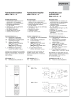
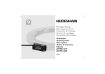
Betriebsanleitung / Operating instructions Ultraschall-Sensoren / Ultrasonic sensors USTI 12 MFB 150 ... Bestimmungsgemäßer Gebrauch Ultraschall-Sensoren USTI 12 MFB 150 ... werden als Bestandteil eines übergeordneten Gesamtsystems zum Erfassen von Objekten eingesetzt. Authorized use Ultrasonic sensors USTI 12 MFB 150 ... are used as a part of a higher-level overall system for detection of objects. -Konformität EMV-Richtlinie DIN EN 60947-5-2 Niederspannungs-73/23/EWG richtlinie93/68/EWG conformity EMV directive DIN EN 60947-5-2 Low voltage 73/23/EWG directive93/68/EWG Sicherheitshinweise Safety instructions Ultraschall-Sensoren USTI 12 MFB 150 ... sind nicht zulässig für Sicherheitsanwendungen, insbesondere bei denen die Sicherheit von Personen von der Gerätefunktion abhängig ist. Ultrasonic sensors USTI 12 MFB 150 ... are not to be used for safety applications, in particular applications in which safety of persons depends on proper operation of the instruments. Ultraschall-Sensoren dürfen nicht in explosionsgefährdeten Räumen betrieben werden. Ultrasonic sensors may not be operated in explosion-hazard areas. Der Betreiber des übergeordneten Gesamtsystems, z.B. einer Maschinenanlage, ist für die Einhaltung der für den speziellen Einsatzfall geltenden nationalen und internationalen Sicherheits- und Unfallverhütungsvorschriften verantwortlich. Bei Maschinenplanung und Verwendung der Ultraschall-Sensoren sind die einsatzspezifischen Sicherheits- und Unfallverhütungsvorschriften einzuhalten, wie z.B.: - EN 60204, Elektrische Ausrüstung von Maschinen - DIN EN ISO 12100, Sicherheit von Maschinen - Grundbegriffe, allgemeine Gestaltungsleitsätze - DIN 57100 Teil 410, Schutz gegen gefährliche Körperströme Montage und elektrischer Anschluss der Ultraschall-Sensoren USTI 12 MFB 150 ... darf nur von Fachpersonal nach geltenden Vorschriften in spannungsfreiem Zustand und bei ausgeschalteter Maschine erfolgen. Die Maschine muss gegen Wiedereinschalten gesichert sein. The operator of the higher-level overall system, e.g. a machine installation, is responsible for complying with the national and international safety and accident prevention regulations which apply to the specific use. When carrying out machine planning and using the Ultrasonic sensors, the safety and accident prevention regulations specific to use must be complied with, e.g.: - EN 60204, Electrical equipment of machines - DIN EN ISO 12100, Safety of machinery - Basic concepts, general principles for design - DIN 57100 Teil 410, Protection against dangerous electric shock Assembly and electrical connection of Ultrasonic sensors USTI 12 MFB 150 ... may only be carried out by skilled personnel according to applicable regulations in de-energized condition and when the machine is switched off. The machine must be secured to ensure that it cannot be switched back on. Funktion Ultraschall-Sensoren USTI 12 MFB 150 ... senden mittels eines Ultraschallwandlers Schallwellen einer bestimmten Frequenz über das Übertragungsmedium Luft aus. Das Senden der Schallwellen erfolgt in zeitlich begrenzten Takten. Derselbe Ultraschallwandler dient in den Sendepausen als Schallempfänger mit ausgeprägter Richtcharakteristik. Durch eine Laufzeitmessung werden die in den Sendepausen vom Zielobjekt reflektierten Schallwellen als Echos im Gerät verarbeitet und daraus ein abstandsproportionales Ausgangssignal gebildet. Durch die kleine Bauform, den kleinen Blindbereich und das sehr schmale Abtastfeld sind die Sensoren besonders für den Einsatz bei begrenzten Platzverhältnissen, wie z. B. in engen Behältern oder Rohren, geeignet. Anwendungsgebiete sind die Objekterkennung, die Distanzmessung und die Füllstandsmessung. Alle Sensoren dieser Baureihe sind über einen Teach-Eingang teachbar. Das Teachen erfolgt durch Verbinden des TeachEingangs mit +UB oder -UB (0 V). Als Ausgangsvarianten sind Sensoren mit Schaltausgang (Transistorausgang pnp, zwei teachbare Schaltpunkte für Fensterauswertung oder als Näherungsschalter; jeweils mit Schließer- oder Öffnerfunktion) oder mit Analogausgang (zwei teachbare Auswertegrenzen; als Strom- oder Spannungsausgang, steigend oder fallend) lieferbar. Die Sensoren besitzen einen Blindbereich von 20 mm direkt vor der Wandleroberfläche. In diesem Bereich ist keine Distanzmessung möglich. Function Ultrasonic sensors USTI 12 MFB 150 ... emit sound waves at a specific frequency through the transmission medium of air by means of an ultrasonic transducer. The sound waves are emitted in time-limited cycles. The same ultrasonic transducer is used as a sound receiver with a distinctive directional characteristic during the transmit pauses. The sound waves reflected in the transmit pauses from the target are processed as echoes in the unit on the basis of a transit-time measurement, and an output signal proportional to the distance is generated from this. With their compact design, very small blind zone, and the narrow detection area, these sensors are particularly suited for use in constricted spaces, such as small containers or pipes. Areas of application are object detection, distance measuring, and fill level sensing. All sensors of this series feature a teach input. For teach-in, connect the teach input with +UB or - UB (0 V). Available output variants are sensors with switching output (transistor output pnp, two teachable switching points for window evaluation or a proximity switch; each with NO or NC function) or with an analog output (two teachable evaluation limits; as current or voltage output, ascending or descending). The Sensors have a blind zone of 20 mm directly in front of the transducer surface. No distance measuring is possible in this area. - Bei Raumtemperatur können praktisch alle Objekte innerhalb des Arbeitsbereiches des Sensors erfasst werden. - At room temperature, virtually all objects within the sensor’s working range can be detected. - Eine große Oberfläche des zu erfassenden Objektes erhöht die Schaltsicherheit. - Objekte mit glatter Oberfläche können bis zu einem Neigungswinkel von ca. 10° sicher erkannt werden. Raue und stark strukturierte Objekte sind mit größeren Neigungswinkeln erfassbar. Physikalische Anwendungsgrenzen - Ultraschall-Sensoren sind aus physikalischen Gründen (Schallgeschwindigkeit in Luft 341 m/s bei 20 °C) relativ langsam. - Aufgrund der Ultraschallfrequenz von 400.000 Hz errechnet sich eine Auflösung von ± 0,9 mm. - Keine Funktion unter Wasser, in Vakuum und bei größeren Überdrücken. - Sehr heiße (> +50 °C) oder sehr kalte Objekte (< -10 °C) können u. U. nicht abgetastet werden (Turbulenzen der Luft mit Brechung und Streuung des Schalls). - Starke Luftströmungen > 20 m/s können die Abtastsicherheit verringern. - Eisbildung auf der Wandleroberfläche reduziert die Empfindlichkeit des Sensors (Abhilfe durch Auftragen einer dünnen Schicht Silikonfett auf die Wandleroberfläche). - Sehr kleine oder sehr schlecht reflektierende (schallabsorbierende) Objekte können u. U. nicht bis zum Grenzabstand erfasst werden. Schallabsorbierende Materialien sind z.B. Schaumgummi, lose Baumwolle, Filz, Textilien, ausgasende Flüssigkeiten, rutschender Sand usw. - Bei zu großer Neigung des zu erfassenden Objektes zur Strahlachse wird nicht mehr genügend Schall in Empfängerrichtung reflektiert (besonders bei größeren, ebenen Flächen). Glatte Objekte können bis zu einer Neigung von 10° sicher detektiert werden. Rauhe Oberflächen unter Umständen bis 60° oder mehr. Montage Die Montage erfolgt über das Gehäusegewinde. - Ultraschall-Sensoren so montieren, dass sich keine Materialien auf der Wandleroberfläche absetzen können. - Starke Fremdschallquellen in der Schallachse von Ultraschall-Sensoren sind zu vermeiden. - Beim Einbau in Rohre muss der Rohrdurchmesser größer als der Schallkeulendurchmesser sein (siehe Abtastfeld). Das Verhalten des Ultraschall-Sensors muss durch Versuche ermittelt werden. - Das Wandlergehäuse des Sensors darf andere Maschinenteile nicht berühren. - Nie die Schallachsen von Geräten der gleichen Baureihe aufeinander richten. Elektrischer Anschluss - Der elektrische Anschluss muss EMVgerecht ausgeführt werden. - Für die Spannungsversorgung muss ein EMV-gerechtes Netzteil verwendet werden. - Der Minuspol der Stromversorgung und der Maschinenkörper müssen geerdet werden. - Anschlusskabel und Stromversorgungsleitungen nicht in unmittelbarer Nähe von Leitungen höherer Spannungen oder mit Leitungen, die induktive oder kapazitive Lasten schalten, verlegen. - Die max. Länge der Anschlussleitungen darf 100 m nicht überschreiten. Der Leitungsquerschnitt muss entsprechend ausgelegt sein (Spitzenstrom!). Der elektrische Anschluss erfolgt über 4‑polige Anschlusskabel mit M12-Steckverbinder. B 07/9.0613de - A large surface of the object to be detected increases the switching reliability. - Objects with smooth surfaces can be detected up to an inclination angle of approx. 10°. Rough and heavily textured objects can be detected at larger inclination angles. Physical application limits - For physical reasons (speed of sound in air 341 m/s at 20 °C), ultrasonic sensors are relatively slow. - The calculated resolution is ± 0.9 mm on the basis of the ultrasonic frequency of 400,000 Hz . - The sensors do not function under water, in a vacuum or at high excess pressures. - Very hot objects (> +50 °C) or very cold objects (< -10 °C) may, under certain circumstances, not be detected (air turbulence with refraction and scattering of the sound). - Strong air flow > 20 m/s may reduce the detection reliability. - Ice formation on the transducer surface reduces the sensitivity of the sensor (this can be remedied by applying a thin coat of silicone grease to the transducer surface). - Very small objects or very poorly reflecting objects (sound-absorbing objects) may, under certain circumstances, not be detected as far as the limit zone. Sound-absorbing materials include foam rubber, loose cotton, felt, textiles, outgassing fluids and slippery sand etc. - If the object to be detected is too greatly inclined with respect to the beam axis, this means that adequate sound will not be reflected in the direction of the receiver (particularly in the case of large, flat surfaces). Smooth objects may be detected reliably up to an angle of inclination of 10°. Rough surfaces may be detected under certain circumstances up to an angle of inclination of 60° or more. Assembly The unit can be mounted using the housing thread. - Mount ultrasonic sensors such that no particles can collect on the converter surface. - Avoid strong external sound sources on the sound axis of ultrasonic sensors. - If fitting in pipes, the pipe diameter must be larger than the sound cone diameter (see detection area). Determine the behaviour of the ultrasonic sensor by means of trials. - The transducer housing of the sensor may not contact other machine components. - Never aim the sound axes of devices of the same series towards each other. Electrical connection - The electrical connection must be made in such a manner as to ensure electromagnetic compatibility (EMC). - Please us an EMC-compliant power pack for the power supply. - The negative terminal of the power supply and the machine body must be connected to ground. - Do not lay connection lead and power supply cables in the direct vicinity of cables conducting high voltages or cables which switch inductive or capacitive loads. - The connection leads may not exceed a max. length of 100 m. The cable crosssection must be designed accordingly (peak current!).voltage. The unit must be connected electrically via a 4-core connection cable with M12 plug connector. Anschlussschema Connection diagram BN = Braun/brown BK = Schwarz/black BU = Blau/blue WH = Weiß/white BN 1 BK 4 WH 2 BU 3 teach pnp LED-Anzeige | LED display Status / Status LED rot / red LED gelb / yellow Normalbetrieb / normal mode PNP aus / off Schaltzustand / switching state Normalbetrieb / normal mode Analog aus / off ein / on - Objekt erkannt / Objekt detected aus / off blinkt / blinking - Kein Objekt erkannt / No objekt detected blinkt / blinking aus / off Teachen / teaching - Unstabile Erkennung / Unstable detection ein / on aus / off Störung / Malfunction letzter Zustand / last state ein / on Funktion Teach-Eingang | Function of teach input Eingangssignal / Input signal Funktion / Function +UB oder / or -UB (0V) Teach-Funktion aktiv / Teach function activ nicht belegt / not used Normalbetrieb / normal mode Teachen des Schaltausgangs (USTI 12 MFB 150 PSOK-IBSL) Die Schaltpunkte können über den TeachEingang innerhalb des Arbeitsbereichs geteacht werden. Zum Teachen muss der Teach-Eingang für min. 1 s mit +UB bzw. -UB (0 V) verbunden werden. Bei nicht funktionierendem Teachvorgang, z.B. außerhalb des Arbeitsbereiches, blinkt die rote LED. Fensterauswertung Schließer Innerhalb des geteachten Fensters ist der Schaltausgang aktiv. - Ultraschall-Sensor anschließen und Spannung anlegen - Objekt auf nahen Schaltpunkt im Abtastfeld platzieren. - Teach-Eingang mit -UB (0 V) verbinden. Nach erfolgreichem Teachvorgang blinkt die gelbe LED. Die rote LED ist aus. - Objekt auf fernem Schaltpunkt im Abtastfeld platzieren. - Teach-Eingang mit +UB verbinden. Nach erfolgreichem Teachvorgang blinkt die gelbe LED. Die rote LED ist aus. - Teach-Eingang von +UB trennen und offen lassen. Teaching the switching output (USTI 12 MFB 150 PSOK-IBSL) The switching points can be taught in the working range via teach input. For teaching purposes, the teach input must be connected to +UB or -UB (0 V) for at least one second. When the teach process could not be proberly made, e.g. beyond scanning range, the red LED is flashing. Window evaluation NO The switching output is active within the teach-in window. - Connect ultrasonic sensor and apply voltage. - Place object on close switching point in the detection area. - Connect teach input with -UB (0 V). After a successful teach-in procedure, the yellow LED should be blinking. The red LED is off. - Place object on distant switching point in the detection area. - Connect teach input with +UB. After a successful teach-in procedure, the yellow LED should be blinking. The red LED is off. - Disconnect teach input from +UB and leave open. Fensterauswertung Öffner Außerhalb des geteachten Fensters ist der Schaltausgang aktiv. Das Teachen erfolgt sinngemäß wie bei Fensterauswertung Schließer, jedoch wird der nahe Schaltpunkt mit +UB und der ferne Schaltpunkt mit -UB (0 V) geteacht. Window evaluation NC The switching output is active outside of the teach-in window. Teaching follows the same principles as Window evaluation for NO, but the close switching point should be taught with +UB and the distant switching point with -UB (0 V). Näherungsschalter Schließer Bei Unterschreiten des geteachten Abstands ist der Schaltausgang aktiv. - Objekt auf den Schaltpunkt im Abtastfeld platzieren. - Teach-Eingang mit +UB verbinden. Nach erfolgreichem Teachvorgang blinkt die gelbe LED. Die rote LED ist aus. -Sensor mit der Hand abdecken (Hautkontakt zur Wandleroberfläche!) oder Sensor ins Leere schauen lassen (kein Objekt innerhalb des Abtastfeldes!). -Teach-Eingang -UB (0 V) verbinden. Nach erfolgreichem Teachvorgang blinkt die gelbe LED. Die rote LED ist aus. - Teach-Eingang von -UB (0 V) trennen und offen lassen. Proximity switch NO If the teach-in distance is fallen short of, the switching output is active. - Place object on switching point in the detection window. - Connect teach input with +UB. After a successful teach-in procedure, the yellow LED should be blinking. The red LED is off. - Cover sensor with the hand (skin contact to transducer surface) or point sensor into space (no object within detection field!). - Connect teach input with -UB (0 V). After a successful teach-in procedure, the yellow LED should be blinking. The red LED is off. - Disconnect teach input from -UB (0 V) and leave open. Näherungsschalter Öffner Bei Überschreiten des geteachten Abstands ist der Schaltausgang aktiv. Das Teachen erfolgt sinngemäß wie bei Näherungsschalter Schließer, jedoch wird der Schaltpunkt mit -UB (0 V) und danach mit +UB geteacht. Proximity switch NC If the teach-in distance is exceeded, the switching output is active. Teaching follows the same procedure as for the Proximity switch NO, but the switching point should be first taught with -UB (0 V) and then with +UB. Alle technischen Angaben beziehen sich auf den Stand 06/13, Änderungen bleiben vorbehalten. Da Irrtümer und Druckfehler nicht auszuschließen sind, gilt für alle Angaben „ohne Gewähr“. © Copyright by di-soric Teachen des Analogausgangs (USTI 12 MFB 150 A-IBSL / ... I-IBSL) Teaching the analog output (USTI 12 MFB 150 A-IBSL / ... I-IBSL) - Im Blindbereich ist keine Distanzmessung möglich (siehe Abtastfeld). - No distance measuring is possible in the blind zone (see detection area). - Die Anfangs- und Endwerte können steigend (0 - 10 V / 4 - 20 mA) und fallend (10 - 0 V / 20 - 4 mA) geteacht werden. - The teach-in procedure for starting and end values can be in ascending (0 ‑ 10 V / 4 - 20 mA) or descending (10 - 0 V / 20 - 4 mA) order. Die Position des Anfangs- und des Endwerts können über den Teach-Eingang innerhalb des Arbeitsbereichs geteacht werden. Zum Teachen muss der TeachEingang für min. 1 s mit +UB bzw. -UB (0 V) verbunden werden. - Objekt an der Position des Anfangswerts (0 V bzw. 4 mA) im Abtastfeld platzieren - Teach-Eingang mit +UB verbinden. Nach erfolgreichem Teachvorgang blinkt die gelbe LED. Die rote LED ist aus. - Objekt an der Position des Endwerts (10 V bzw. 20 mA) im Abtastfeld platzieren - Teach-Eingang mit -UB (0 V) verbinden. Nach erfolgreichem Teachvorgang blinkt die gelbe LED. Die rote LED ist aus. The positions of the starting and end values can be taught within the working range via teach input. For teaching, the teach-in input must be connected to +UB or -UB (0 V) for at least one second. - Place object at the position of the starting value (0 V or 4 mA) in the detection area. - Connect teach input with +UB. After a successful teach-in procedure, the yellow LED should be blinking. The red LED is off. - Place object at the position of the end value (10 V or 20 mA) in the detection area. - Connect teach input with -UB (0 V). After a successful teach-in procedure, the yellow LED should be blinking. The red LED is off. Wartung und Reparatur Maintenance and repair - Keine lösungsmittelhaltigen Reiniger verwenden. - Please do not use cleaning agents containing solvents. - Ultraschall-Sensoren nicht mit heißem Dampf reinigen. - Do not clean ultrasonic sensors with hot steam. Ultraschall-Sensoren USTI... sind weitestgehend wartungsfrei. Ablagerungen auf der Schallwandleroberfläche regelmäßig mit einem weichen Tuch entfernen. Reparatur nur durch di-soric. Ultrasonic sensors USTI... are largely maintenance-free. Regularly remove deposits on the surface of the sound transducer using a soft cloth. Repair by di-soric only. Gewährleistung Es gelten die gesetzlichen Gewährleistungsbestimmungen. Maßzeichnung / Dimensional drawing Warranty The legal warranty regulations apply. Abtastfeld / Detection area 20 140 120 100 80 60 40 20 mm (typ.) 0 Technische Daten Technical data 20 °C, 24 V DC Arbeitsbereich Scanning range 20 ... 150 mm Sendefrequenz Operating frequency 400.000 Hz Betriebsspannung Service voltage 10 ... 30 V DC 15 ... 30 V DC ( ... A-IBSL) Restwelligkeit Ripple 10 % Eigenstromaufnahme Internal power consumption30 mA Schaltausgang Switching output Transistor pnp, 100 mA, NO/NC (… PSOK-IBSL) Schaltfrequenz Switching frequency 13 Hz Wiederholgenauigkeit Repeat accuracy 0,5 % Analogausgang Analog output 0 ... 10 V (… A-IBSL) 4 ... 20 mA (… I-IBSL) Lastwiderstand Load resistance min. 1.000 Ω (… A-IBSL) max. 300 Ω (… I-IBSL) Linearität Analogausgang Linearity analog output < 1% / Sn max. Umgebungstemperatur Ambient temperature -25 ... +70 °C Schutzart Protection class IP 65 Gehäusematerial Casing material Messing vernickelt / nickel-plated brass All technical specifications refer to the state of the art 06/13, they are subject to modifications. As typographical and other errors cannot be excluded, all data are given „without engagement“. di-soric GmbH & Co. KG Steinbeisstraße 6 DE 73660 Urbach Tel. +49 (0) 71 81 / 98 79-0 Fax +49 (0) 71 81 / 98 79-179 [email protected] Internetwww.di-soric.com