1
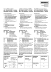
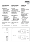
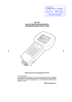
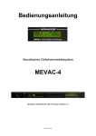
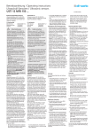
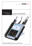
Temperaturmessverstärker IM34-12Ex-CRi/K63 Temperature measuring amplifier IM34-12Ex-CRi/K63 Amplificateur de mesure pour thermocouple IM34-12Ex-CRi/K63 Gerätekurzbeschreibung • Eingänge für Ni100- bzw. Pt100-Widerstandsthermometer nach IEC 751, Pt100-, Cu50-, Cu53-, Cu100- und CuZn-Widerstandsthermometer nach GOST, Thermoelemente nach IEC 584 sowie Thermoelemente Typ L, A-1, A-2, A-3 und M nach GOST und für Kleinspannungen (mV-Bereich) • Eingangskreise eigensicher Ex ia • Anwendungsbereich nach ATEX: II (1) G, II (1) D, II 3 G • Zugelassen für Einbau in Zone 2 • Drahtbruchüberwachung • Kurzschlussüberwachung nur für Widerstandsthermometer • Thermoelementmessung mit externer und interner Kaltstellenkompensation • Galvanische Trennung der Ein- und Ausgangskreise zueinander, untereinander und zur Versorgung • Analoger Stromausgang 0/4...20 mA • Grenzwertrelais • Temperaturlineare Umsetzung • Parametrierung durch PC über Programmieradapter IM-PROG (zusätzlich zu bestellen – Ident-Nr.: 6890422) • Gehäuse mit codierten abziehbaren Klemmenblöcken • Simulation der Ausgänge • Universelle Betriebsspannung (20...250 VAC/20...125 VDC) Short description • Inputs for RTDs Ni100 or Pt100 acc. to IEC 751, Pt100, Cu50, Cu53, Cu100 and CuZn acc. to GOST, thermoelements acc. to IEC 584 and thermoelements type L, A-1, A-2, A-3 und M acc. to GOST and for low voltages (mV range) • Intrinsically safe input circuit Ex ia • Area of application acc. to ATEX: II (1) G, II (1) D, II 3 G • Approved for installation in zone 2 • Wire-break monitoring • Short-circuit monitoring only for RTDs • Thermoelement measuring with external and internal cold junction compensation • Galvanic isolation between input and output circuits and supply • Analogue current output 0/4...20 mA • Limit value relay • Temperature linear conversion • Parameterisation via PC via programming adapter IM-PROG (to be ordered additionally – ident-no.: 6890422) • Housing with coded and removeable terminal blocks • Simulation of outputs • Universal operating voltage (20...250 VAC/20...125 VDC) Description brève • Entrées pour résistances Ni100 ou Pt100 suivant IEC 751, résistances Pt100, Cu50, Cu53, Cu100 et CuZn suivant GOST, thermocouples suivant IEC 584 ainsi que thermocouples L, A-1, A-2, A-3 et M suivant GOST et pour basses tensions (plage mV) • Circuits d‘entrée à sécurité intrinsèque Ex ia • Champ d‘application suivant ATEX: II (1) G, II (1) D, II 3 G • Certifié pour montage en zone 2 • Surveillance aux ruptures de câble • Surveillance aux courts-circuits seulement pour résistances • Mesure du thermocouple par compensation du point froid externe et interne • Séparation galvanique entre circuits d‘entrée et sortie et par rapport à l‘alimentation • Sortie de courant analogique 0/4...20 mA • Relais de valeur limite • Conversion linéaire en fonction de la température • Paramétrage par PC par adaptateur de programmation IM-PROG (à commander séparément – N° d‘ident. 6890422) • Boîtier avec blocs de bornes codés débrochables • Simulation de sorties • Tension de service universelle (20...250 VAC/20...125 VDC) Klemmenbelegung (Fig. 2) Eigensichere Eingänge an Klemmen 1–6 1, 2 Thermoelement- und mV-Eingang 3 – 6 Eingang für Widerstandsthermometer 7, 8 Analoger Stromausgang (0/4...20 mA) 9, 10 Grenzwertrelais 11,12 Betriebsspannungsanschluss Leitungsanschluss durch anhebende Käfige mit unverlierbaren Schrauben, Anschlussquerschnitt: ≤ 1 x 2,5 mm2, 2 x 1,5 mm2 oder 2 x 1 mm2 mit Ader-Endhüsen Terminal configuration (Fig. 2) Intrinsically safe inputs at terminals 1–6 1, 2 Thermoelement and mV input 3 – 6 RTD input 7, 8 Analogue current output (0/4...20 mA) 9, 10 Limit value relay 11,12 Supply voltage connection Connection via lifting cages with captive screws, connection profile: ≤ 1 x 2.5 mm2, 2 x 1.5 mm2 or 2 x 1 mm2 with wire sleeves Raccordement des bornes (Fig. 2) Entrées à sécurité intrinsèque aux bornes 1–6 1, 2 Entrée pour thermocouple et mV 3 – 6 Entrée pour résistances 7, 8 Sortie de cour. analogique (0/4...20 mA) 9, 10 Relais de valeur limite 11,12 Raccordement de la tension de service Raccordement du câble par des cages levantes avec des vis imperdables, section raccordable: ≤ 1 x 2,5 mm2, 2 x 1,5 mm2 ou 2 x 1 mm2 avec cosses LED-Anzeigen (Fig. 1) Pwr grün Betriebsbereitschaft ó rot Fehler 1 gelb Relais erregt Hinweis: Statusanzeigen, siehe Tab. 1 auf nächster Seite LED indications (Fig. 1) Pwr green power on ó red error 1 yellow relay energised Attention: Status indications, see table 1 on the next page Visualisations par LED (Fig. 1) Pwr verte tension de service ó rouge défaut 1 jaune relais excité Conseil: visualisations de l‘état, voir tableau 1 à la page suivante 1 /1010 IM34-12Ex-CRi/K63 Fig. 1 Fig. 2 10 11 12 7 8 9 to PC via IM-PROG µP Pwr mV 1 4 PC-Connect RTD Zone 2: Do not disconnect when live! 5 2 3 2 6 3 7+ 0/4...20 mA 8 R L £ 600 W 2 3 6 5 4 IM34-12Ex-CRi K63 4 1 +1 TC YE GN RD Pwr 9 £ 250 VAC/120 VDC 10 £ 500 VA/60 W £ 2A 11 12 Power Tab. 1: Statusanzeigen/Status indications/Visualisation de l‘état LED Pwr LED ó Die Werte entsprechen der Leuchtcharakteristik in %/The values agree with the light characteristic in %/Les valeurs correspondent à la caractéristiques lumière en % 0 = 0 %, 10 = 10 %, 50 = 50 %, 100 = 100 % 100 Fehler/Error/Fuite Ausgabe eines Fehlerstromes, dabei ist Relais abgefallen/ Output of error current, moreover relay is de-energised/ Sortie d'un courant de fuite, de plus le relais est désexcité Beschreibung/Description 0 – Betrieb/Operation/Fonctionnement 100 10 ✔ Eingangsfehler/Input error/Erreur d‘entrée 10 100 ✔ Softwarefehler/Software error/Erreur de logiciel 0 100 ✔ Hardwarefehler/Hardware error/Erreur de matériel 100 50 ✔ Messspanne zu klein/Measuring span to short/Plage de mesure trop faible 100 50 – Messbereich bzw. Schaltschwelle außerhalb des Anwendungsbereichs des RTD bzw. Thermoelements/Measuring range/switching threshold outside the operating range of the RTD or thermoelement/Plage de mesure ou seuil de commutation au dehors du champ d‘application de la RTD ou du thermocouple 50 50 ✔ Leitungsabgleich/Line compensation/compensation de ligne (LEDs blinken gegenphasig zueinander/LEDs flashing alternatingly/ Clignotement de LEDs en opposition de phase) 100 50 ✔ Leitungsabgleich nicht korrekt/Line compensation not correct/ Compensation de ligne incorrecte 50 0 – Stromausgang und Grenzwertrelais im Simulationsbetrieb/current ouput and limit value relay in simultaneous operation/Sortie de courant et relais de valeur limite en mode de simulation 2 /1010 IM34-12Ex-CRi/K63 Parametrierung und Einstellungen Die Parametrierung und Einstellung des IM34... wird über den DTM durchgeführt (siehe auch beigefügte Dokumentation „Software-Installation PACTware™ und Geräte-DTMs“, D201354). Der TURCK-Adapter IM-PROG dient zur Verbindung zwischen dem Gerät und Ihrem PC. Verbinden Sie dazu den 3,5-mm-Stecker mit dem Messverstärker (PC-Connect) und den RS232-Stecker mit der seriellen Schnittstelle ihres PCs. Die Einstellungen sind als Auswahl bzw. numerische Eingabe in den Feldern des DTM möglich und selbsterklärend: Parameterisation and adjustments The IM34... is parameterised and adjusted via the Device Type Manager (see also “PACTware™ and devices DTM software installation”, D201354). The TURCK adapter IM-PROG is needed to establish the connection between the device and your PC. For this it is necessary to connect the 3.5 mm connector to the measuring amplifier (PCConnect) and the RS232 connector to the serial interface of your PC. The following settings are available as an entry or numerical setting via the DTM: Paramétrage et réglage Le paramétrage et le réglage d‘un IM34... se font par le DTM (voir aussi „installation du logiciel PACTware™ et des DTM d‘appareils“, D201354). Le IM-PROG de TURCK sert à connecter l'appareil à votre PC. Branchez le connecteur 3,5 mm sur l‘amplificateur de mesure (PCConnect) et le connecteur RS232 sur l‘interface série de votre PC. • Modus Auswahl des Anschlusselements: Pt/Ni100, Cu50, Cu53, Cu100 und CuZn, Thermoelement, mV-Eingang und Anwahl des Leitungsabgleiches. Die folgenden Einstellmöglichkeiten sind abhängig von der in „Modus“ durchgeführten Auswahl: • Mode Selection of the connection element: Pt/Ni100, Cu50, Cu53, Cu100 and CuZn, thermoelement, mV input and selection of line compensation. • Mode Sélection de l‘élément à raccorder: Pt/Ni100, Cu50, Cu53, Cu100 et CuZn thermocouple, entrée mV et sélection de la compensation de ligne. Les autres possibilités de réglage dépendent de la valeur sélectionnée sous „Mode“: – Thermoelement Auswahl der Typen: E, J, K, N, R, S, T, L, B, A-1, A-2, A-3 und M Hinweis: Werden die Leitungen des Thermoelements bis zum Temperaturmessverstärker geführt, empfiehlt TURCK den Einsatz des Kaltstellenkompensationsmoduls IM-3-CJT (Ident-Nr.: 6900524). – Anschlussart für Temperaturwiderstand Auswahl 2-, 3-, 4-Leiter-Technik – Messbereich Der Messbereich ergibt sich aus Endtemperatur und Anfangstemperatur. Nach Auswahl des Anschlusstyps wird der Messbereich im unteren Bereich der DTMBenutzeroberfläche angezeigt. Diese Angaben entsprechen dem eingestellten analogen Ausgangssignal 0/4...20 mA. Die Anfangstemperatur hängt vom Typ des Thermoelements/Temperaturwiderstands ab. Die eingestellte Anfangstemperatur entspricht dem analogen Ausgangssignal von 0/4 mA. Die Endtemperatur hängt wie die Anfangstemperatur vom Typ des Thermoelements/ Temperaturwiderstands ab. Die eingestellte Endtemperatur entspricht dem analogen Ausgangssignal von 20 mA. – Ausgangssignal Zur Auswahl stehen 0...20 mA bzw. 4...20 mA. Diese Werte entsprechen den eingestellten Anfangs- und Endtemperaturen – Leitungsabgleich Beim 2-Leiter-Anschluss muss der Widerstand der Anschlussleitung abgeglichen werden. Dazu ist die Messstelle kurzzuschließen, der Modus „Leitungsabgleich” zu wählen und den Button „Übertragen“ anklicken. Die LEDs Pwr und ó blinken abwechselnd. Sobald der Abgleich beendet ist (LED Pwr = 100 %, LED ó = 10 %), kann der Kurzschluss aufgehoben werden. Der vor dem Abgleich gewählte Modus bleibt beibehalten. – Thermoelement Type selection: E, J, K, N, R, S, T, L, B, A-1, A-2, A-3 and M Note: If the cables of the thermoelements are routed up to the temperature measuring amplifier, TURCK suggests the application of a cold junction compensation module IM-3-CJT (Ident-no.: 6900524) – Connection mode of temperature resistor 2, 3 or 4-wire connection technology – Measuring range The measuring range is composed of the lower and upper temperature value. After selecting the connecting type, the measuring range is indicated in the lower section of the DTM. These indications accord to the adjusted analogue output signal of 0/4...20 mA. The lower temperature depends on the type of thermoelement/temperature resistor and accords to an output signal of 0/4 mA. The upper limit temperature also depends on the type of thermoelement/ temperature resistor. The adjusted upper limit temperature accords to an analogue output signal of 20 mA. – Output signal The selection comprises 0...20 mA 4...20 mA signals. The adjusted values correspond to the adjusted lower and upper limit temperatures. – Line compensation In case of 2-wire connections, the resistor can be adapted to the connection cable. For this it is necessary to short the measuring point. Select "line compensation" mode and then click the button "transmit". The LEDs Pwr and ó flash alternately. If line compensation is done (LED Pwr = 100 %, LED ó = 10 %), continue by removing the short-circuit. The mode selected before line compensation remains. – Thermocouple Sélection des types: E, J, K, N, R, S, T, L, B, A-1, A-2, A-3 et M Attention: si les lignes du thermocouple sont guidées jusqu‘au convertisseur de température, TURCK recommande l‘utilisation du module de point froid IM-3-CJT (n° d‘identité: 6900524). – Mode de raccordement pour la résistance de température Sélection de la technique 2, 3 ou 4 fils – Plage de mesure La plage de mesure se compose de la température finale et de début. Après la sélection du type, la plage de mesure est indiquée dans la zone inférieure du DTM. Ces données correspondent au signal de sortie analogique 0/4...20 mA programmé. La température de début dépend du type de thermocouple et de la résistance de la température. La température de début programmée correspond au signal de sortie analogique de 0/4 mA. La température finale dépend, tout comme la température de début, du type de thermocouple et de la résistance de température. La température finale programmée correspond au signal de sortie analogique de 20 mA. – Signal de sortie Vous avez le choix parmi 0...20 mA ou 4...20 mA. Les valeurs programmées correspondent aux températures de début et finale programmées. – Compensation de ligne En cas de raccordement en technique 2 fils, il est possible de compenser la résistance du câble de raccordement. Dans ce cas, il faut court-circuiter le point de mesure et choisir le mode „Leitungsabgleich” (Compensation de ligne). Les LED Pwr et ó clignotent alternativement. Dès que le réglage est terminé (LED Pwr = 100 %, LED ó = 10 %), le court-circuit peut être levé. Le mode choisi avant le réglage reste maintenu. Weitere Informationen siehe nächste Seite. More information see next page. Pour plus d’informations, voir la page suivante. 3 /1010 The following settings depend on the selections made in the "Mode" menu: Les réglages suivants peuvent être sélectionnés ou entrés comme valeur numérique dans les champs du DTM: IM34-12Ex-CRi/K63 – Strom im Fehlerfall Auswahl von 0 mA bzw. > 22 mA – Error current Either 0 mA or > 22 mA – Courant en cas d‘erreur Choix entre 0 mA ou > 22 mA – Schaltschwelle Eingabe eines Wertes für Temperatur bzw. Kleinspannung, bei dem das Grenzwertrelais aktiviert wird. – Switching threshold Entry of a temperature value or a low voltage value at which the limit value relay is activated. – Seuil de commutation Entrée d‘une valeur de température ou d‘une très basse tension à laquelle le relais de valeur limite est activé. Montage und Installation (Fig. 3) Die angeschlossenen Betriebsmittel (Temperaturwiderstand, Thermoelement) müssen die Voraussetzung zum Einsatz im explosionsgefährdeten Bereich erfüllen (EN 60079-14). Mounting and installation (Fig. 3) The connected apparatus (RTDs, thermoelements) must meet the requirements for use in explosion hazardous areas (EN 60079-14). Montage et installation (Fig. 3) Les matériels électriques (résistances, thermocouple) raccordés doivent remplir les exigences pour le fonctionnement dans la zone explosible (EN 60079-14). Das Gerät ist aufschnappbar auf Hutschiene (EN 60715) oder aufschraubbar auf Montageplatte. Geräte gleichen Typs können direkt aneinander gesetzt werden. Sorgen Sie für eine ausreichende Wärmeabfuhr. The device is suited for snap-on clamps for hat rail mounting (EN 60715) or for screw panel mounting. Devices of the same type may be mounted directly next to each other. It must be ensured that heat is conducted away from the device. Mounting and installation must be carried out in accordance with the applicable regulations. The operator is responsible for compliance with the regulations. L‘appareil est encliquetable sur rail symétrique (EN 60715) ou peut être monté sur panneaux. Les appareils du même type peuvent être montés directement l‘un à côté de l‘autre. Une évacuation suffisante de la chaleur est nécessaire. Le montage et l’installation doivent être effectués conformément aux prescriptions locales valables, dont le respect est la responsabilité de l’exploitant. The removeable terminal blocks are coded and may only be plugged into the designated sockets. The coding system may not be altered or damaged. Les blocs de bornes débrochables sont codés et peuvent seulement être enfichés sur le socle prévu. Il n'est pas permis de modifier ou d'endommager le codage. Schützen Sie das Gerät ausreichend gegen Staub, Schmutz, Feuchtigkeit und andere Umwelteinflüsse. Auch gegen energiereiche Strahlung, Risiken mechanischer Beschädigung, unbefugter Veränderung und zufälliger Berührung müssen Vorkehrungen getroffen werden. The device must be protected against dust, dirt, moisture and other environmental influences as well as against strong electro-magnetic emissions. It should also be protected against the risks of mechanical damaging, unauthorised access and incidental contact. L‘appareil doit être suffisamment protégé contre les poussières, la pollution, l‘humidité et les autres influences d‘environnement, ainsi que contre le rayonnement fort, les risques de dommages mécaniques, la modification nonautorisée et les contacts accidentels. Führen Sie sämtliche Installationen EMVgerecht durch. All installations must be carried out observing the regulations of EMC protection. Toutes les installations doivent être effectuées conformément à la CEM. Besondere Bedingungen für den Einsatz in Zone 2 Bei Einbau in Zone 2 muss das Gerät in ein Gehäuse nach EN 60079-15 mit einer Schutzart mindestens IP54 nach IEC/EN 60529 montiert werden. Special conditions for application in zone 2 For installation in zone 2 the device must be installed in a housing which complies with the requirements of EN 60079-15 with a minimum protection degree of IP54 according to IEC/EN 60529. Conditions particulières en cas d‘utilisation en zone 2 En cas de montage en zone 2, l’appareil doit être monté dans un boîtier suivant EN 60079-15 ayant un mode de protection d’au moins IP54 suivant IEC/EN 60529. Bei Einbau in Zone 2 ist das Benutzen der Schalter sowie das Verbinden und Trennen der Anschlüsse von nicht energiebegrenzten Stromkreisen unter Spannung ist nur zulässig, wenn keine explosionsfähige Atmosphäre vorliegt. With mounting in zone 2 the operation of the switches as well as the connecting and disconnecting of energised non energy limited circuits is only permitted in non-explosive atmosphere. En cas de montage en Zone 2, l‘utilisation des interrupteurs ainsi que la connexion et la séparation sous tension des raccordements de circuits de courant sans limitation d’énergie est uniquement autorisée en cas d‘absence d‘une atmosphère explosible. Führen Sie die Montage und Installation den gültigen Vorschriften entsprechend durch. Dafür sind Sie als Betreiber verantwortlich. Die abziehbaren Klemmenblöcke sind codiert und können nur auf den vorgesehenen Sockel gesteckt werden. Die Codierung darf nicht verändert oder beschädigt werden. Für den Versorgungsstromkreis sind externe Maßnahmen zu treffen, die verhindern, dass die Bemessungsspannung durch vorübergehende Störungen um mehr als 40 % überschritten wird. Bei der Verdrahtung mit Litzendrähten sind die Drahtenden unbedingt mit Aderendhülsen fest zu fixieren. 4 /1010 For the supply circuit arrangements have to be taken externally, that the rated voltage is exceeded not more than 40 % by transient disturbances. The application of litz-wires recommends the fixation of cable ends with wire sleeves. Des mesures externes pour le circuit d‘alimentation doivent être prises, qui empêchent que la tension nominale est dépassée plus de 40% suite à des interférences temporaires. Lors du câblage avec des fils torsadés, les extrémités de fil doivent être fixées absolument par des cosses. IM34-12Ex-CRi/K63 ì Wichtige Hinweise zum Einsatz von Geräten mit eigensicheren Stromkreisen Das vorliegende Gerät verfügt an den blau gekennzeichneten Klemmen 1 – 6 über Stromkreise der Zündschutzart „Eigensicherheit“ für den Explosionsschutz gemäß EN 60079-11. Die eigensicheren Stromkreise sind von autorisierten Prüfungsstellen bescheinigt und für die Verwendung in den jeweiligen Ländern zugelassen. Beachten Sie für den bestimmungsgemäßen Betrieb in explosionsgefährdeten Bereichen unbedingt die nationalen Vorschriften und Bestimmungen und halten Sie diese ein. Nachfolgend erhalten Sie einige Hinweise, insbesondere hinsichtlich der Rahmen-Richtlinie der Europäischen Union 94/9/EG (ATEX). Das vorliegende Gerät ist ein zugehöriges Betriebsmittel, das neben eigensicheren auch über nichteigensichere Stromkreise verfügt. Es darf nur außerhalb des Ex-Bereiches in trockenen, sauberen und gut überwachten Räumen installiert werden. Bei Errichtung innerhalb des explosionsgefährdeten Bereichs der Kategorie 1 und 2 müssen die Geräte in entsprechende Gehäuse eingebaut werden. Dieser Einbau muss gesondert geprüft und bescheinigt werden. Liegt eine Konformitätsaussage oder Erklärung des Herstellers als Gerät der Kategorie 3 vor, darf eine Installation in Zone 2 erfolgen. Die besonderen Bedingungen zum sicheren Betrieb sind zu beachten. An die eigensicheren Anschlüsse können eigensichere elektrische Betriebsmittel angeschlossen werden. Alle Betriebsmittel müssen die Voraussetzungen zum Betrieb in der vorhandenen Zone des explosionsgefährdeten Bereiches erfüllen. Führen die eigensicheren Stromkreise in staubexplosionsgefährdete Bereiche der Zone 20 bzw. 21, ist sicherzustellen, dass die Geräte, die an diese Stromkreise angeschlossen werden, die Anforderungen für Kategorie 1D bzw. 2D erfüllen und entsprechend bescheinigt sind. Werden die Betriebsmitteln zusammengeschaltet, muss der „Nachweis der Eigensicherheit“ durchgeführt werden (EN 60079-14). Bereits durch den einmaligen Anschluss von eigensicheren Stromkreisen an nicht eigensichere Kreise ist eine spätere Verwendung als Betriebsmittel mit eigensicheren Stromkreisen nicht mehr zulässig. Für die Errichtung eigensicherer Stromkreise, die Montage an äußeren Anschlussteilen sowie für die Beschaffenheit und Verlegung von Leitungen gelten einschlägige Vorschriften. Leitungen und Klemmen mit eigensicheren Stromkreisen müssen gekennzeichnet werden – bei farbiger Kennzeichnung ist hellblau zu verwenden. Sie sind von nichteigensicheren Stromkreisen zu trennen oder müssen eine entsprechende Isolierung aufweisen (EN 60079-14). Zwischen den Anschlussteilen eigensicherer und nichteigensicherer Stromkreise muss ein Abstand (Fadenmaß) von 50 mm eingehalten werden. Anschlussteile eigensicherer Stromkreise müssen 6 mm voneinander getrennt sein. Halten Sie von den eigensicheren Anschlüssen dieses Gerätes den vorgeschriebenen Abstand zu geerdeten Bauteilen und Anschlüssen anderer Geräte ein. Soweit nicht ausdrücklich in der gerätespezifischen Anleitung angegeben, erlischt die Zulassung durch Öffnen des Gerätes, Reparaturen oder Eingriffe am Gerät, die nicht vom Sachverständigen oder Hersteller ausgeführt werden. Sichtbare Veränderungen am Gerätegehäuse, wie z. B. bräunlich-schwarze Verfärbungen durch Wärme sowie Löcher oder Ausbeulungen weisen auf einen schwer wiegenden Fehler hin. Daraufhin das Gerät unverzüglich abschalten. Bei zugehörigen Betriebsmitteln müssen die angeschlossenen eigensicheren Betriebsmittel ebenfalls überprüft werden. Die Überprüfung eines Gerätes hinsichtlich des Explosionsschutzes kann nur von einem Sachverständigen oder vom Hersteller vorgenommen werden. Der Betrieb der Geräte ist nur im Rahmen der auf dem Gehäuse aufgedruckten bzw. in der Dokumentation aufgeführten zulässigen Daten gestattet. Insbesondere sind evtuell aufgeführte Besondere Bedingungen in der EG-Baumusterprüfbescheinigung bzw. Conditions of Certification des IECEx CoC zu beachten. Vor jeder Inbetriebnahme oder nach Änderung der Gerätezusammenschaltung ist sicherzustellen, dass die zutreffenden Bestimmungen, Vorschriften und Rahmenbedingungen eingehalten werden, ein bestimmungsgemäßer Betrieb gegeben ist und die Sicherheitsbestimmungen erfüllt sind. Die Montage und der Anschluss des Gerätes muss von geschultem und qualifiziertem Personal mit Kenntnis der einschlägigen nationalen und anzuwendenden internationalen Vorschriften über den Ex-Schutz durchgeführt werden. Die wichtigsten Daten aus der EG-Baumusterprüfbescheinigung sind umseitig aufgeführt. Alle gültigen nationalen und internationalen Bescheinigungen der TURCKGeräte finden Sie im Internet (www.turck.com). Die Besonderen Bedingungen IECEx CoC sind unter www.iecex.com zu finden. Weitere Informationen zum Ex-Schutz stellen wir Ihnen auf Anfrage gern zur Verfügung. 5 /1010 ì Important information on use of devices with intrinsically safe circuits This device is equipped with circuits featuring protection type „intrinsic safety“ for explosion protection per EN 60079-11 at terminals 1 – 6 which are marked in blue. The intrinsically safe circuits are approved by the authorised bodies for use in those countries to which the approval applies. For correct usage in explosion hazardous areas please observe and follow the national regulations and directives strictly. Following please find some guidelines referring to the framework directive of the European Union 94/9/EC (ATEX). This device is classified as an associated apparatus which is equipped with intrinsically safe and non-intrinsically safe circuits. Therefore it may only be installed in the non-explosion hazardous area in dry clean and well monitored locations. Installation in explosion hazardous areas of the categories 1 and 2 requires mounting of the devices in appropriate housings, followed by special tests and authorization. If a declaration of conformity or declaration of the manufacturer as a category 3 device exists, the device may be installed in zone 2. Special instructions for safe operation must be observed. It is permitted to connect intrinsically safe equipment to the intrinsically safe connections of this device. All electrical equipment must comply with the regulations applying to use in the respective zone of the explosion hazardous area. If the intrinsically safe circuits lead into explosion hazardous areas subject to dust hazards, i.e. zone 20 or 21, it must be ensured that the devices which are to be connected to these circuits, meet the requirements of category 1D or 2D and feature an according approval. When interconnecting devices within such an assembly it is required to keep and provide a proof of intrinsic safety (EN 60079-14). Once that intrinsically safe circuits have been connected to the non-intrinsically safe circuit, it is not permitted to use the device subsequently as intrinsically safe equipment. The governing regulations cover installation of intrinsically safe circuits, mounting to external connections, cable characteristics and cable installation. Cables and terminals with intrinsically safe circuits must be marked. In case of color coding, light-blue must be used. They should be separated from non-intrinsically safe circuits or must feature appropriate insulation (EN 60079-14). A thread measure of 50 mm must be observed between intrinsically safe and non-safe connections. Between intrinsically safe connections a thread measure of 6mm is required. The approval expires if the device is repaired, modified or opened by a person other than the manufacturer or an expert, unless the device-specific instruction manual explicitly permits such interventions. Visible damages of the device’s housing (e. g. black-brown discolouration due to heat accumulation, perforation or deformation) indicate a serious error and the device must be turned off immediately. When using associated apparatus it is required to check the connected intrinsically safe equipment too. This inspection may only be carried out by an expert or the manufacturer. Operation of the devices is only permissible in accordance with the allowed specifications which are printed on the housing and/or listed in the documentation. Special conditions mentioned in the EC type test examination certificate i.e. Conditions of Certification of the IECEx CoC have to be followed. Prior to initial set-up or after every alteration of the interconnection assembly it must be assured that the relevant regulations, directives and framework conditions are observed, that operation is error-free and that all safety regulations are fulfilled. Mounting and connection of the device may only be carried out by qualified and trained staff familiar with the relevant national and international regulations of explosion protection. The most important data from the EC type examination certificate are listed overleaf. All valid national and international approvals covering Turck devices are obtainable via the Internet (www.turck.com). The special conditions of IECEx CoC can be accessed on www.iecex.com. Further information on explosion protection is available on request. ì Informations importantes sur l‘utilisation d‘appareils avec des circuits de courant à sécurité intrinsèque Cet appareil est équipé aux bornes bleues 1 – 6 de circuits de courant en mode de protection „sécurité intrinsèque“ pour la protection contre les explosions suivant EN 60079-11. Les circuits de courant à sécurité intrinsèque disposent d‘un certificat accordé par les laboratoires agréés et sont permis pour l‘utilisation dans les pays concernés. Son fonctionnement conformément aux dispositions dans les atmosphères explosives implique le respect des prescriptions et dispositions nationales. Ci-dessous sont énumérés quelques conseils, particulièrement concernant la directive-cadre de l‘Union européenne 94/9/EC (ATEX). Cet appareil est du matériel électrique équipé non seulement de circuits de courant à sécurité intrinsèque, mais aussi de circuits de courant non à sécurité intrinsèque. Il ne peut être installé en dehors de la plage Ex dans des lieux secs, propres et bien surveillés. En cas de réalisation dans la zone explosible des catégories 1 et 2, les appareils sont à monter dans des boîtiers adéquats. Cette installation doit être contrôlée et certifiée. Si une déclaration de conformité ou explication du fabricant comme appareil de la catégorie 3 est disponible, une installation en zone 2 peut être effectuée. Les instructions particulières d‘un fonctionnement sûr sont à respecter. Du matériel électrique à sécurité intrinsèque peut être raccordé aux connexions à sécurité intrinsèque à condition que ce matériel électrique à sécurité intrinsèque remplisse les exigences pour le fonctionnement dans la zone actuelle de la zone explosible. Lorsque les circuits de courant à sécurité intrinsèque se trouvent dans les zones présentant des risques d'explosion de poussière de la zone 20 ou 21, il doit être assuré que les appareils qui seront raccordés à ces circuits de courant, remplissent les exigences de la catégorie 1D ou 2D et qu'ils disposent d'un certificat. En cas d‘interconnexion de matériels électriques la „preuve de la sécurité intrinsèque“ doit être remplie (EN 60079-14). Même le raccordement unique de circuits de courant à sécurité intrinsèque à des circuits non à sécurité intrinsèque ne permet plus un fonctionnement ultérieur comme matériel électrique à sécurité intrinsèque. Pour la réalisation de circuits de courant à sécurité intrinsèque, le montage à des pièces de raccordement extérieures, ainsi que pour la qualité et le cheminement des conducteurs les prescriptions concernées sont à respecter. Les câbles et les bornes à circuits de courant à sécurité intrinsèque doivent être marqués – en cas de marquage coloré utiliser bleu clair. Ils doivent être déconnectés de circuits de courant non à sécurité intrinsèque ou ceux doivent être équipés d'une isolation appropriée (EN 60079-14). Une distance de 50 mm (écart) entre les pièces de raccordement à sécurité intrinsèque et les circuits de courant non à sécurité intrinsèque est à respecter. Les pièces de raccordement de circuits de courant à sécurité intrinsèque doivent être séparés 6 mm l'une de l'autre. Quant aux raccordements à sécurité intrinsèque de cet appareil, la distance prescrite entre les composants mis à la terre et les raccordements d‘autres appareils est à respecter. Sauf s‘il est indiqué dans le mode d‘emploi spécifique de l‘appareil, l‘homologation n‘est plus valable en cas d‘ouverture de l‘appareil, ou si des réparations ou des interventions sont effectuées à l‘appareil par des personnes autres que des spécialistes ou que le fabricant. Des transformations visibles au boîtier de l‘appareil telles que par ex les décolorations brunâtres noires par la chaleur ainsi que des trous ou des gonflements, indiquent un défaut grave impliquant la désactivation immédiate de l‘appareil. Quant au matériel électrique associé, le matériel électrique à sécurité intrinsèque raccordé doit également être contrôlé. Le contrôle d‘un appareil en ce qui concerne la protection contre les explosions ne peut être effectué que par un spécialiste ou le fabricant. Le fonctionnement des appareils est uniquement permis dans le cadre des données admissibles imprimées sur le boîtier ou mentionnées dans la documentation. Particulièrement les conditions particulières eventuellement énumérées dans l‘attestation d‘examen de type CE ou les Conditions of Certification de l‘IECEx CoC sont à respecter. Avant toute mise en service ou après modification de l‘interconnexion des appareils, on doit veiller à ce que les dispositions, les prescriptions et les conditions-cadre concernées sont respectées, que le fonctionnement est conforme aux dispostions et que les dispositions de sécurité sont remplies. Le montage et le raccordement de l‘appareil ne peut être effectué que par des personnes qualifiées qui sont au courant des prescriptions nationales et internationales sur la protection Ex concernées. Les données essentielles de l‘attestation d‘examen CE figurent au verso. L‘ensemble des certificats nationaux et internationaux des appareils TURCK peuvent être obtenus par internet (www.turck.com). Les Conditions particulières IECEx CoC peuvent être consultées sur www.iecex. com. Plus d’informations sur la protection Ex peuvent être obtenues sur demande. IM34-12Ex-CRi/K63 Dit apparaat beschikt aan de klemmen 1 - 6 (blauw) over stroomkringen in de beschermingswijze „Intrinsiek veilig“ voor de explosiebeveiliging volgens EN 60079-11. Voor correct gebruik in ontploffings-gevaarlijke atmosferen moeten de nationale voorschriften en bepalingen onvoorwaardelijk gerespecteerd worden. Het apparaat is bijhorend elektrisch materieel en mag niet in de Ex-atmosfeer worden geïnstalleerd. Apparaten van de categorie 3 mogen in zone 2 worden geïnstalleerd. Hierbij de bijzondere instructies in acht nemen! Alle nationale en internationale certificaten kunnen via internet opgevraagd worden. ǹȣIJȒ Ș ıȣıțİȣȒ įȚĮșȑIJİȚ İıȦIJİȡȚțȐ ĮıijĮȜȒ țȣțȜȫμĮIJĮ ıIJȚȢ İʌĮijȑȢ 1 - 6 (μʌȜȑ) ıȪμijȦȞĮ μİ IJȘȞ ĮȞIJȚİțȡȘțIJȚțȒ ʌȡȠıIJĮıȓĮ țĮIJȐ Ǽȃ 50020. ǹʌĮȚIJİȓIJĮȚ Ș ıȣμμȩȡijȦıȘ EN 60079-11. μİ IJȠȣȢ İșȞȚțȠȪȢ țĮȞȠȞȚıμȠȪȢ țĮȚ IJȚȢ ȠįȘȖȓİȢ ȖȚĮ ıȦıIJȒ ȜİȚIJȠȣȡȖȓĮ ıİ İʌȚțȓȞįȣȞİȢ ȖȚĮ ȑțȡȘȟȘ ʌİȡȚȠȤȑȢ. Ǿ ıȣıțİȣȒ țĮIJȘȖȠȡȚȠʌȠȚİȓIJĮȚ ȦȢ ıȣȞİȡȖĮȗȩμİȞȘ ıȣıțİȣȒ țĮȚ įİȞ ʌȡȑʌİȚ ȞĮ IJȠʌȠșİIJİȓIJĮȚ ıİ İʌȚțȓȞįȣȞİȢ ʌİȡȚȠȤȑȢ. ȈȣıțİȣȑȢ țĮIJȘȖȠȡȓĮȢ GR Oheisen laitteen sinisellä merkatut liittimet 1 - 6 ovat tarkoitettu räjähdysvaarallisessa laiteen suojaukseen ja ne ovat suojausluokaltaan ”luonnostaan vaarattomia” standardin EN 60079-11 mukaisesti. Räjähdysvaarallisissa tiloissa toimittaessa on sääntöjen mukaisesti ehdottomasti noudatettava ja seurattava kansallisia direktiivejä ja säännöksiä! Tämä laite on luokiteltu apulaitteeksi ja sitä ei saa asentaa räjähdysvaaralliseen tilaan. Laiteluokan 3 laitteet ovat asennettavissa luokan 2 räjähdysvaaralliseen tilaan. Pyydämme huomioimaan erityisohjeet! Kaikki kansalliset ja kansainväliset hyväksynnät ovat saatavilla Internet osoitteestamme. Questa unità dispone di circuiti a sicurezza intrinseca tra i terminali 1 - 6 (azzurro) in accordo alle norme di protezione alle esplosioni EN 60079-11. E‘ necessario seguire le normative e direttive nazionali per una corretta applicazione in aree a rischio di esplosione . Questa unità è classificata come apparato associato e non può essere installato in aree pericolose. Arnesi della categoria 3 possono essere installati nella zona 2. Osservi indicazione speciale! Tutte le approvazioni nazionali e internazionali possono essere richiamate via Internet. Det foreliggende apparat indeholder klemmer 1 - 6 (blå) med strømkredse af beskyttelsesklasse ”egensikkerhed” for eksplosionsbeskyttelse iht. EN 60079-11. Til den forcskrevne drift i eksplosionsfarlige områder, skal de nationale foreskrifter og bestemmelser ubetinget iagttages og overholdes. Apparatet er klassificeret som et tilhørende apparat og må ikke installeres i Ex-området. Apparater i kategori 3 kan installeres i zone 2. Bemærk venligst særlige oplysninger! Alle nationale og internationale godkendelser er lagt på internettet. Este equipamento tem circuitos de segurança intríseca nos terminais 1 - 6 (azul) de acordo com á proteção á explosão da norma EN 60079-11. É necessário seguir os regulamentos e directivas nacionais para uma correcta operação nas áreas explosivas. Este equipamento está classificado como aparelho associado e não pode estar instalado numa área explosiva. Instrumentos da catogoria 3 podem ser instaladas na Zona 2. Considerar as referências especias! Todas as aprovações nacionais e internacionais podem ser vistas na internet. Este aparato incluye circuitos de seguridad intrínseca para protección de explosiones en los terminales 1 - 6 (azul) según EN 60079-11. Se requiere seguir las regulaciones y directivas nacionales para su correcta operativa en las áreas de peligro de explosiones. El aparato está clasificado como asociado y no debería instalarse en áreas de peligro. Los dispositivos de categoría 3 se pueden instalar en zona 2. Por favor, observe las consideraciones especiales! Todas las aprobaciones nacionales e internacionales pueden consultarse vía Internet. Данный прибор имеет на клеммах 1 - 6 обозначенных голубым цветом, токовые цепи , безопасные по конструкции согласно Евронормам EN60079-11. 50020. Для правильной эксплуатации во EN взрывоопасных условиях необходимо придерживаться национальных предписаний и требований. Прибор является дополнительным электрическим устройством и не может размещаться во взрывоопасной зоне. Приборы категории 3 могут инсталлироваться в зоне 2. Обращать внимание на особые указания! Все национальные и международные сертификаты доступны через Интернет. Denna utrustning egensäkra kretsar, för explosionsskydd enligt EN 60079-11. Dessa kretsar är terminalerna 1 - 6 och är blåmarkerade. Nationella regler och bestämmelser för använding inom Ex-område måste följas. Utrustningen klassas som tillbehör och får ej monteras i explosionsfarliga utrymmen. Kategori 3 produkter kan installeras i zon 2. Beakta specifik notering! Alla nationella och internationella certifikat kan tas hem via Internet. NL 3 μʌȠȡȠȪȞ ȞĮ İȖțĮIJĮıIJĮșȠȪȞ ıİ ȗȫȞȘ 2. ȆĮȡĮțĮȜȠȪμİ, ʌĮȡĮIJȘȡİȓıIJİ IJȚȢ ȣʌȠįİȓȟİȚȢ! ǵȜİȢ ȠȚ İșȞȚțȑȢ țĮȚ ȠȚ įȚİșȞİȓȢ İȖțȡȓıİȚȢ İȓȞĮȚ įȚĮșȑıȚμİȢ μȑıȦ įȚĮįȚțIJȪȠȣ. I DK E RUS FIN P S Internet: www.turck.com → www.turck.de → Support → Download EG-Baumusterprüfbescheinigung EC-Type examination certificate Attestation d’examen CE de type Nr. 4024-1M Declaration of Conformity 0102 Konformitätserklärung Diese Konformitätserklärung entspricht der Europäischen Norm EN 45014 ”Allgemeine Kriterien für Konformitätserklärungen von Anbietern”. Die Grundlage der Kriterien sind internationale Dokumente, insbesondere ISO/IEC Leitfaden 22, 1982: ”Information on manufacturer’s declaration of conformity with standards or other technical specifications”. This “Declaration of Conformity“ complies with the European Standard EN 45014 ”General criteria for a supplier’s declaration of conformity”. These criteria are based on the relevant international documentation, particularly the ISO/IEC Guide 22, 1982: ”Information on the manufacturer’s declaration of conformity with standards or other technical specifications”. Nr./No. erklären in alleiniger Verantwortung, dass die Produkte ≤5V U0 I0 ≤ 2 mA P0 ≤ 2,6 mW Kennlinie: linear/characteristic curve: linear/courbe caractéristique: linéaire Li 0,2 mH Ci vernachlässigbar/negligible/négligeable L0 /C 0 – [Ex ia/ib] IIB 1000 mH/1000 µF – [Ex ia/ib] IIC 1000 mH/100 µF – Ex nL IIC 100 mH/3,6 µF – Ex nL IIB 100 mH/18 µF declare under our sole responsibility that the products Temperatur-Meßumformer Typ IM34 - **Ex-**i auf die sich die Erklärung bezieht, mit den folgenden Normen übereinstimmen to which this declaration relates are in conformity with the following standards EN 61326-1:2006 EN 61010-1:2001 und wo anwendbar and where applicable EN 60079-0:2009 EN 61241-11:2006 TÜV 02 ATEX 1898/TÜV 06 ATEX 552978 X EN 60079-11:2007 EN 60079-15:2005 Gemäß den Bestimmungen der Richtlinie (falls zutreffend) -25...+70 °C Ta Following the provisions of Directive (if applicable) EMV - Richtlinie / EMC Directive 2004/108/EG Richtlinie ATEX 100a / Directive ATEX 100a 94 / 9 / EG Niederspannungsrichtlinie / Low Voltage Directive 2006/95/EG 15. Dez. 2004 23. März 1994 12. Dez. 2006 Fig. 3 18 Weitere Normen, Anmerkungen additional standards, remarks 100 Die Niederspannungsrichtlinie ist nicht anwendbar bei Betrieb des Produktes im explosionsgefährdeten Bereich. In diesem Fall sind alle grundlegenden Zielsetzungen im Hinblick auf die Niederspannung von der Richtlinie 94/9/EG Anhang II Punkt 1.2.7 abgedeckt. The low voltage directive is not applicable when the product is installed in the hazardous area. In this case all Low Voltage essential objectives are covered by the Directive 94/9/EG Annex II 1.2.7. Aussteller der EG-Baumusterbescheinigung: TÜV Nord Cert GmbH Co KG Am TÜV 1, D-30519 Hannover Kenn-Nr. 0032, Registriernummer: TÜV 02 ATEX 1898, TÜV 06 ATEX 552978 X Mülheim, den 19.10.10 92 104 89 110 Kennz.: Kennz.: II (1) G II (1) D II 3 G EN 60715-TH35 (i.V. W. Stoll) Ort und Datum der Austellung / Place and date of issue *D201355ßß1010* HANS TURCK GMBH & CO KG WITZLEBENSTR. 7, D - 45472 MÜLHEIM A.D. RUHR ø 4,5 Name und Unterschrift des Befugten / Name and signature of authorized person 35 Irrtümer und Änderungen vorbehalten / Subject to change without notice / Sous réserve de modifications • © Hans Turck GmbH & Co. KG 2010 Hans Turck GmbH & Co. KG • Witzlebenstraße 7 • 45472 Mülheim/Ruhr • Germany • Tel. +49 (0) 208/4952-0 • Fax +49 (0) 208/4952-264 • [email protected] • www.turck.com D201355 1010 Wir / We II (1) G [Ex ia Ga] IIC/IIB / II (1) D [Ex ia Da] IIIC II 3 G Ex nA nC [ic Gc] IIC/IIB T4 Gc/ II 3 G Ex nA [ic Gc] IIC/IIB T4/Gc