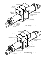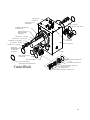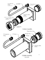
1
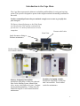
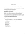
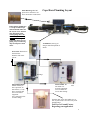
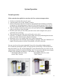
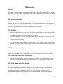
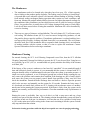
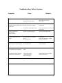
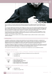
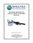
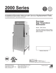
Cape Horn Extreme
INSTALLATION MANUAL
Spectra Watermakers, Inc.
20 Mariposa Road, San Rafael, CA 94901
Phone 415-526-2780 Fax 415-526-2787
E-mail: [email protected]
www.spectrawatermakers.com
Server/masterdoc/manualscurrent/capehorn 12-18-04
1
Introduction to the Cape Horn
The Cape Horn represents the ultimate in reliability and flexibility for racing and cruising
yachts. This system is designed to operate in the toughest and most demanding conditions in
the world.
Prudent seamanship dictates that you maintain enough reserve water to get safely into
your next port.
The Spectra Intensifier known as the Clark Pump
was introduced in 1997 and has continually improved since. It is built of modern non corrosive
composites.
Pressure relief valve
Front View
Quick disconnect fitting to
facilitate maintenance.
Double rubber mounts
for to absorb vibration
Primary feed pump inlet module.
Includes the feed pump, cooling fan, charcoal
filter for the flushing system, manual flush
valve, service valve and service port . Compact
and streamlined plumbing. Cooling fan is included for long life. Local control switch for
maintenance.
Secondary feed pump module.
Includes the feed pump, cooling fan
And 5 micron filter. Local control
switch for maintenance.
2
Getting Started
Unpack the system and inspect it to make sure that it has not been damaged in shipment.
Refer to the shipping list for your system to make sure you have received all of the components listed. Do not discard any packaging until you have found and identified all of the
parts. The small installation parts are listed on the kit list.
Warning! We will not be held responsible for shortages and or freight damage that are not
reported within thirty days of the ship date.
Study the system layout diagram, component photos and descriptions before beginning your
installation. This will assist you in understanding the function of each component.
Layout the system. Before starting the installation identify the location where each module
and component will be placed. Insure that there is proper clearance around the components
for removal of filters and system service. Also check to make sure you have adequate tubing
and hose before starting so additional parts may be ordered.
Cape Horn Shipping List
•
High Pressure Clark Pump and a 40” Reverse Osmosis Membrane Module.
• Feed pump inlet module with fresh water flush system.
• Feed pump module with 5 micron filter housing.
• Accumulator Tank
• Seawater strainer
• Monitor Gauge panel
• Installation Fittings Kit
• Service Hose kit
• Hand held Salinity monitor
• 5/8”(14.75mm) Hose
• 1/4 product tubing (50’)
3
Brine Discharge thru hull
place above waterline or tee
brine into another visible drain.
Cape Horn Plumbing Layout
Plastic fittings should have
3-4 wraps of Teflon tape
and will thread almost all
the way in. Leave the first
pipe thread uncoated.
Avoid getting dirt or debris in the system during
assembly. Avoid tight
bends and elbows. Secure
piping away from moving
objects and protect from
chafe.
Accumulator, Factory precharged. Install and plumb as
shown.
Fresh water flush inlet to
charcoal filter.
Plumb to fresh water
system.
discharge
Inlet pump modules.
Mount vertically as
low as practical, no
more than 4’ (1.1 M)
above waterline and
not over electrical
equipment.
Leave clearance below
for filter change.
5 micron filter. Do
not mount over
electrical equipment.
Leave clearance below for filter change.
inlet
Seawater inlet from a low bubble free intake. System needs a clear flow away from
head discharge.
Feel Free to Consult Factory
Regarding your application.
4
Product Water and Pressure Gauge Tube Installation
Sampling Tap for testing the product
water or for service procedures.
Put enough tube on this port to reach
your service (pickling) container.
Product to tank.
Route the product water from the
valve into the top of the tank. Install
a tee in the water fill or tap a pipe
thread into an inspection port.
DO NOT! feed into a vent line,
manifold or the bottom of the tank.
Make sure that there is no restriction
in this piping.
Product sampling valve. Mount using the supplied plastic straps as shown.
Note: the handle is pointing in the direction of the
flow.
Pressure Gauge
Use accumulator port to connect the
pressure gauge. Tubing must be pressure rated to 150 PSI (10 BAR)
Product Flow meter
Plastic fittings should have 3-4 wraps of Teflon tape and
will thread almost all the way in. Leave the first pipe thread
uncoated. Avoid getting dirt or debris in the system during
assembly. Secure piping away from moving objects and
protect from chafe. Exercise care not to cross thread the
fittings. See the tube assembly instructions next page.
Back view of instrument panel.
Product Water Flow
Product Ports are
located here
Product fitting
5
Remove one of the product port plugs (from either end) and
thread in the product fitting with Teflon tape sealant.
Body
O-ring
Spacer
Grab Ring
Nut
Step 1:
Tubing
Dissemble fitting components
1/2" max
Step 2: Install the Nut first then use the bevelled side of the Spacer to push the
Grab Ring onto the tube no more than 1/2". Slip the O-ring over the tube
to hold the Spacer in place. If the Grab Ring is pushed too far, trim back
the tube so about 1/4" of tube extends past the O-ring.
Step 3: Gently fit the tube into the body and loosely thread on the nut.
Step 4: Push the tube into the body until it bottoms out then hand tighten the nut.
DO NOT OVER TIGHTEN!
1/4" Tube Fitting Assembly
6
Cape Horn Wiring Diagram
Route a heavy pair of wires from the main DC electrical panel to the Feed Pump location.
Connectors to the terminal block. Seal connectors. The switch located near the feed pump is
pre-wired.
Voltage drop will impair performance of the system.
Cooling fans
Main Electrical Panel
Positive buss
Feed Pumps
15 amp breakers 12VDC
7 amp 24VDC
Feed Pump wiring, Red is Positive
Black is Ground.
Negtive buss
+
_
Cooling Fan are connected parallel with the Feed
pump. Same color code.
To battery, #8 gauge or larger
Wire Size Guide for 12V
Protect with 15 Amp Fuse or Circuit Breaker
# 10 Gauge (6mm) to 15 feet (4.5M)
# 8 Gauge (10 mm) to 25 feet (7.5M)
#6 Gauge (16mm) to 35 feet (10.6M)
Wire Size Guide for 24V
Protect with 7 Amp Fuse or Circuit Breaker
#12 Gauge(4mm) to 10 feet (3M)
#10 Gauge (6mm) to 25 feet (7.6M)
#8 Gauge (10mm) to 35 feet (10.6M)
7
New System Start-Up and Testing
Avoid running the system if the vessel is in contaminated water, such as in a harbor or canal. The system should be fully run tested before leaving port. If the location or weather prevents proper testing refer to the section “Dry Testing.”
Warning! Damage may occur if the purge sequence is bypassed and the membrane is
pressurized with storage chemical in it.
1. First Check That:
•
•
•
•
•
Thru-hull inlet valve is open and the Brine discharge valve is open.
All of your hose connections are tight.
You remove the green tag with the spacer under the pressre relief valve.
Open the pressre relief valve 1/2 turn.
The sampling valve is set to the sample position.
Remove Tag and Washer!
Open 1/2 Turn to Purge Chemicals!
2. Turn on one of the feed water pumps. Check that it is primed by inspecting the brine discharge. Turn off and then turn on the other pump to prime.
3. Run the system using both pumps, without pressure for 20 minutes to purge the storage
chemicals. The system should have an open flow pressure on the gauge of about 30 PSI (2
Bar)
4. Close the pressure relief valve. The pressure should rise to 80-90 PSI (5.5-6.5Bar) and
after several minutes start making water. If the vessel is located in brackish or fresh water
the pressure will be lower
5. Allow the system to run for 5-10 minutes and then test the product with your hand held
salinity tester. If the product is below 750 PPM it is considered potable and may be diverted
to the tank.
8
Dry Testing With Artificial Ocean
If it is not possible to test run the system with the boat in the water testing may be accomplished with
an artificial ocean. Purchase enough aquarium salts to make 5 gallons (20 liters) of salt water.
Make sure that the domestic water system is powered up and that there is water in the tank. Confirm
that the Charcoal filter is installed in the Fresh water flush module and that the domestic water line
had been installed and all valves are open.
1.
2.
3.
4.
5.
5.
Open Pressure Relief Valve on the Clark Pump. Remove the green tag and spacer!
Close the yellow service valve on the inlet module. This will be the center location.
Open the grey fresh water flush valve.
Start the feed pump and let it run 20 minutes to purge the storage chemical.
Stop the feed pump
Hook up your Inlet and Brine discharge service hoses per the photo and route them into the 5 gallon (20 Liter) container. Turn your Product sample valve to the sample position. Route the product output into the bucket.
6. Restart the feed pump and fill the bucket with fresh water from the brine discharge. Stop the
pump and close the fresh water flush valve.
7. Rotate the yellow service valve to the service position.
8. Mix the salt to the proper proportion or use an aquarium hydrometer to adjust the salinity level.
9. Start the feed pump, allow to prime and then close the pressure relief valve. The system should
build pressure and after several minutes start making water.
10. Run the system under pressure and check for proper operation and leaks.
After testing the system stop the feed pump and replace the brine discharge hose. Restart and drain
the bucket. You can now store the system by using the above procedure for adding fresh water to the
bucket and using the Storage procedure. If the system is to continue to be commissioned performing
a fresh water flush will hold the system for 4-5 days.
Valves in flush position
Valves in service position
Inlet service hose connected.
Connecting the Brine
Discharge service hose.
9
System Operation
Normal operation
If the system has been pickled or stored use the New system startup procedure.
1. Check to see that the inlet seacock is open.
2. Turn the product valve to the “Sample” position.
3. Start the feed pumps and check for flow by inspecting the brine discharge or checking
for pressure on your analog gauge. If there is no flow open the pressure relief valve on
the Clark pump and bleed the air out of the feed pumps by running them one at a time.
4. After five minutes check the product water with your hand held salinity tester. If it is
good you may divert it into your tank.
5. Run the system until you have filled your tank or have made enough to meet your requirements for several days.
6. Turn on the fresh water flush valve and close the service valve.
7. Flush for 2 1/2 minutes or until the pressure drops on the gauge indicating that the membrane is flooded with fresh water. Stop the feed pump.
8. Return the service valve and the flush valve to their run positions.
9. The system may be run with only one feed pump in extremely cold water conditions or if
highly efficient operation is desired. Water quality will suffer somewhat.
You may now leave the system unattended for up to five days without further attention
We recommend operating the system for longer periods and effecting a FW flush than running the machine every day and not flushing the system, Remember that you need to run the
system almost a half hour to make the flushing water. You may notice that the system output
is higher while charging your batteries as the machine is voltage sensitive.
Inlet Module with valves in the
Inlet Module with valves in the
normal “Run” Position.
“flush” Position.
Open
Closed
Closed
Open
10
Long Term Storage Procedures
Watermakers are best run continuously. When not in use, biological growth in the membrane is the leading cause of membrane fouling. A warm environment will cause more
growth than a cold environment. The fresh water flush system will greatly reduce biological growth but may not stop it completely in certain conditions. If an optional “Zeta Guard”
or Z-Brane water treatment system is installed in the system, then three to five day flushing
intervals will maintain the system as long as fresh water is provided and the charcoal filter
maintained.
System Storage or “Pickling”
If the system is to be left unused for more than five days, perform the following storage procedure. The procedure introduces a chemical compound into the system that prevents biological growth. This procedure requires de-chlorinated water which can be made with the
Spectra’s charcoal filter. Charcoal filters last a maximum of 6 months once wetted.
Spectra SC-1 a special storage compound used by the US Navy. It is formulated to be
compatible with the modern engineering plastics and composites in the Spectra pumps.
Do not use any substitute except propylene Glycol. If you wish to use glycol for storagefollow the winterizing instructions. SC-1 Storage Compound has to be mixed at a ratio
of 1 Spectra container to 3 gallons (12L) of fresh water to have the proper solution for
short term storage (under two months use 1/2 of a container)
Caution! Avoid contact with skin, eyes, or lungs with the storage chemical.
11
Storage Procedure
1. Perform a fresh water flush as described in the normal operation section. Shut down the
feed pump but leave the valves in the flush position.
2. Remove the quick disconnect fitting from the brine discharge outlet of the Clark pump, and
replace with a quick disconnect from your service kit, fitted to a hose, and lead the hose to a 5
gallon bucket or container.
3. Start and run the feed pump until you have one gallon of fresh water in the bucket.
4. Mix 1 container of SC-1 storage compound with the water in the bucket.
5. Connect the service hose, using the garden hose barb fitting from your service kit, to the
service port of the fresh water flush module. Lead the hose into the bucket. Turn the service
valve on the fresh water flush module 180°, so the intake is now coming from the bucket.
6. Make sure the pressure relief valve on the
Clark pump is Open (unpressurized)
by turning 1/2 turn counterclockwise
7. Turn on the feed pump. Circulate the storage chemical in the system for approximately 10
minutes. Turn off the feed pump when finished.
Clean Up:
Remove the quick disconnect from the Clark pump brine discharge, and replace the original
hose that leads to the thru-hull. You may at this point, if you choose to, pump the bucket dry
by using the feed pump switch. Stop when the bucket is empty.
Turn the service valve 180° back to its original position, and remove the service hose.
Close the seacock and drain and clean the strainer and any filters in the system. Reassemble
dry.
12
Winterizing
1. Close yellow service valve, open the Grey flush valve and run the feed pump 4 minutes
to effect a complete fresh water flush. Shut the pump and flush valve off.
2. Connect your inlet service hose and your brine discharge service hose place them in your
service container or bucket.
3. Turn the service valve to the service position.
4. Pour 2 gallon (8L) of Propylene Glycol in the bucket.
5. Make sure that the pressure relief valve is open (un-pressurized).
6. Turn on the feed pump and re-circulate the chemical for 20 minutes.
7. Stop the pump. Reconnect the brine discharge hose. Restart the pump until the bucket is
empty.
8. Close the seawater intake and the service valve. Drain the strainer the hose leading to the
inlet module. Disconnect the product tubing and blow any residual water out of the tubing with compressed air.
Valves in flush position
Valves in service position
Open the pressure relief valve
Connecting brine discharge hose
13
Maintenance
General
Periodically inspect the entire system for leakage and chafe on the tubing and hoses. Repair
any leaks you find as soon as practical. Some crystal formation around the Clark pump
blocks is normal. Wipe down any salt encrusted areas with a damp cloth.
The Seawater Strainer
The sea water strainer’s stainless steel element should be inspected, removed, and cleaned as
needed. Be careful to ensure that the thru-hull is closed before disassembly and the gasket is
in place before reassembly. . When the system is put into storage, remove, rinse, and reassemble dry to impede corrosion. Check frequently during operation.
The Prefilter
•
•
•
Service the prefilter on a regular basis. The pressure will drop on the remote gauge when
the filter becomes dirty. Extremely dirty filters will harm system performance and may
cause the feed pump to cycle on the high pressure switch.
To service the filters shut off the service valve open the housing, discard the old filter,
Clean out the housing bowl, reassemble the housing with new 5 micron filter element.
Leave dry until next startup.
Use only Spectra approved filters or you may void your warranty. The filters may be
cleaned several times with a soft brush and water in a bucket. Occasionally, lightly lube
the filter housing O-ring with silicone grease.
Oil Water Separator (Optional)
To install Oil Water Separator capability install the additional filter housing with its oil removal filter upstream of the 5 micron filter. Service at the same time as the 5 micron filter.
The Charcoal Fresh Water Flush Filter
•
Replace the charcoal filter element at least every 6 months! This filter protects the membrane by removing chorine from the fresh flush water. Use only a Spectra replacement!
The Feed Pump and Clark Pump
The feed water pumps and the Clark pump require no routine maintenance except inspection
for leaks. Tighten any hose clamps or fittings the show signs or leakage. The HP fittings
threaded into the Clark pump are o-ring seals with a straight thread. These should never leak
and should never be over tightened. If one of the tube nuts starts to leak it can be usthreaded, sealed with a bit of silicone grease or silicone seal and with two wrenches tightened with two wrenches very tight!
14
The Membranes
•
The membranes need to be cleaned only when they have lost up to 15% of their capacity
due to fouling or the product quality degrades. The leading cause of fouling is from biological growth that occurs when the system is left unused without flushing or pickling. Fouling
from mineral scaling can happen during operation under certain sea water conditions, and
from rust. Monitor the product salinity and feed pressure for higher than normal readings for
the conditions. Other conditions can cause high pressure such as cold feed water or clogged
filters. Low product flow is usually due to low voltage, damaged feed pump or Clark pump.
Look for all other causes before cleaning the membrane. Membrane life can be shortened by
excessive cleaning.
•
There are two types of cleaners: acid and alkaline. The acid cleaner (SC-3) will remove mineral scaling. The alkaline cleaner (SC-2) is used to remove biological by-products, oil, and
dirt particles that get past the prefilters. If membrane performance is reduced and they have
not been pickled recently, cleaning with both chemicals is recommended. The acid cleaner
should be used first. If the membrane fails to respond to both cleanings, this is an indication
of another problem with the system, or that it is time to replace the membrane. Contact
Spectra Watermakers before removing a membrane.
Membrane Cleaning
For normal cleaning, the SC-3 Acid Cleaning Compound is used first, then the SC-2 Alkaline
Cleaning Compound. If known bio-fouling is present, the SC-2 may be used first. Using hot water if possible, up to 120° (45C) is recommended as it greatly enhances the ability of the cleaners
to do their jobs.
If the history of the system is unknown or has been left “unpickled” for an extended length of
time and biological growth is present, it is recommended that the system is cleaned with SC-2,
using an alternate source of unchlorinated fresh water before the system is run under pressure. A
simple test can be performed to see if biological growth has occurred. Before running the system, remove the prefilters and examine their condition If the housings are full of smelly discolored water, the system was not properly stored. Install clean prefilters if they were bad. Next
check the membrane. Detach the brine discharge hose and lead to a bucket. Open the pressure
relief valve one turn, and manually run the system for 30 seconds. Examine the brine water: if
it’s discolored and smells bad, perform an SC-2 cleaning with an alternate source of unchlorinated water before running the system pressurized. If the brine is fairly clean, the system can be
purged, run normally, and checked for performance. Clean the membranes only if performance is
reduced.
Heating the water is preferable. One way to do this is to find a camp stove and use a large
stainless steel pot to heat the solution in. The cleaning solution throughout the system will heat as
it circulates in and out of the pot. An alternative is to heat the one or two gallons of initial water
to 120° on the main stove before mixing in the cleaner and circulating it into the system. Periodically stop and reheat the solution.
Perform the cleaning procedures while the ship is in acceptable sea water for purging and testing.
15
Note: Procedures are the same for the SC-2 and SC-3 cleaners
A Spectra Cleaning Compound (SC-2 or SC-3) must be mixed with fresh water at a ratio of 1 container of compound to 3 gallons (12L) of unchlorinated water to have the proper solution. An average of two gallons (8L) of water is already present inside a 150 system . This water has to be figured into the mixture. A 150 system will use 1 container of compound,
Cleaning Procedure:
1. Close the service valve, open the flush valve and run the feed pump for 4 minutes to
flush the system. Stop the pump and close the flush valve.
2. Connect your inlet service hose and the brine discharge service hose. Open the flush valve
and start the pump until you get a gallon (4L) of water in the bucket.
3. Turn the service valve to the service position.
4. Make sure that the Pressure relief valve is open (un-pressurized).
5. Mix the cleaning chemical in the bucket.
6. Start the system and circulate the chemical through the system for the required time.
7. Stop the pump, replace the brine discharge hose and start the pump until the bucket is
empty. Stop the pump and rotate the service valve back to the run position. Restart the
pump and run for 20 minutes to flush the chemicals out of the system.
(Do Not Close the Pressure Relief Valve!)
8. The system may now be restarted to make water, flushed or stored.
Valves in flush position
Open the pressure relief valve
.
Valves in service position
Connecting brine discharge hose
16
Suggested Spares
Short term trips, weekends etc.
We suggest a basic cruise kit A. Kit consists of 6 ea, 5 micron filters and two SC-1 storage
chemicals.
2 to 6 months at a time.
Two basic cruise kits, One each replacement charcoal filter. One replacement feed pump head.
Longer than 6 months,
Additional filters, offshore cruising kit consisting of Clark pump seals, O-rings, tools and
membrane cleaning chemicals. One replacement strainer screen, O-ring for strainer screen,
O-rings for filter housing
Part Number
Spectra Watermakers parts list:
SC-1 STORAGE CHEMICAL
SC-2 CLEANER
SC-3 CLEANER
BASIC CRUISE A
5 MIC FILTER
CHARCOAL FILTER
6” STRAINER SCREEN
OIL/WATER FILTER
FEED PUMP HEAD
6” STRAINER O-RING
FILTER HOUSING O-RING
OFF SHORE KIT
20” MEMBRANE
P/N FT-CHE-SC1
FT-CHE-SC2
FT-CHE-SC3
KIT-BCK-A
FT-FTC-5
FT-FTC-CC
FT-STN-6S
FT-FTC-OW
SO-STN-6SS
SO-FHS-10H
KIT-OFFSH
FT-MB-20
17
Troubleshooting Deluxe Systems
Symptom
Feed pump runs but no pressure.
Cause
Feed pump air locked
Pressure relief valve open
Feed Pump starts but shuts down on Prefilter excessively clogged.
high pressure.
Closed valve or blockage in flow.
Remedy
Open pressure relief valve to bleed
the air then close to start.
Close valve.
Change filter.
Check flow path for closed valve or
kink in hose.
Low Water production
High amperage.
High Feed pressre
Strainer or prefilter clogged.
Service prefilter and strainer.
Low Water production, Low
pressure.
Pressure Relief valve partially
open.
Worn Pump head,
Close Valve
Check flow should be 1.4 GPM
Replace Pump Head.
Water production normal
High feed pressure high amperage.
Cold seawater temperature
Fouled membrane
Normal condition
Clean membrane.
Water production normal
Lower pressure lower amperage
Warm Sea Water or Brackish
water.
Normal Condition.
Asymmetrical pressure and flow
readings between pump shifts
Check valve leaking
failed annular ring.
Shaft Seal leaking.
Contact Dealer or see the Clark
Pump repair manual.
18
5/8 Quick Disc. Hose Barb
PL-QDC-HB5/8
3/8 NPT Quick Disc. Body
PL-QDC-BD3/8
3/8NPT Nylon Hex Plug
PL-HP-3/8
1/8"FPTX1/4"Tube Fitting Ell.
PL-FTE-1/8X1/4P
Pressure Vessel Ring
FT-PV-ER
Pressure Vessel End Cap
FT-PV-EP
3/8"NPTX1/2"Tube SS Fitt.. St.
PL-MTS-3/8X1/2S
Connector O-ring
SO-HPP-CT
40” High Pressure Vessel
FT-PV-40
1/2” High Pressure Tube
PL-NLT-1/2HP
Low Pressure Filter Housing (Whole Assembly)
FT-FTH-10L
3/4"MPT X 5/8"HB X 5/8" HB
PL-TEE-3/4M5/8B
#8 Hose Clamp
PL-CLP-8SS
3/4”NPT X 5/8” Hose Barb Ell
PL-HBE-3/4X5/8
Cooling Fan Kit
KIT-FK-12, 24
Heat Sink
EL-FP-FPHS
5 Micron Filter Cartridge
FT-FTC-5
3/8”NPT X 5/8” Hose Barb Ell
PL-HBE-3/8X5/8
Ventura Intake Module
FM-VT-ITM
Feed Pump Assembly (Whole Pump With Heat Sink)
KIT-FP-SF12, 24
Pump Head Assembly With Pressure Switch
PL-PMP-SFPH
Sea Strainer (Whole Assembly)
FT-STN-5
Strainer Seal
SO-STN-5SS
Strainer Screen
FT-STN-5S
19
1/2” Tube Fitting Hex Nut
PL-HWR-1/2HN
1/2” SS. Ferrule
PL-HWR-1/2FR
3/4”-16 Straight Fitting O-ring
SO-FT-STF
Connector O-ring
SO-HPP-CT
1/2” High Pressure Tube
PL-NLT-1/2HP
3/8 NPT Quick Disc. Body
PL-QDC-BD3/8
Front View
5/8 Quick Disc. Hose Barb
PL-QDC-HB5/8
Plate Bracket End Cap
FM-PVB-PBE
3/4”NPT X 1/2” Hose Barb Elbow
PL-HBE-3/4X1/2
3/4”NPTX3/4”FPT
PVC Valve
PL-VLV-3/4PVC
Rear View
Plate Bracket
FM-PVB-PB
Rubber Mount
HD-RBP-RM
Nylon Spacer
HD-SPN-MKINS
Clear Filter Housing (Bowl & Cap)
FT-FTH-10L
Filter Housing Seal
SO-FHS-10H
Charcoal Filter Cartridge
FT-FTC-CC
3/4” 3-Way Valve
PL-VLV-3W3/4
3/4”NPTX5/8” Hose Barb
PL-HBS-3/4X5/8
20
3/4” Clamp
PL-CLP-3/4CAR
!/4” 3-Way Valve
PL-VLV-3W1/4
1/4”NPTX1/4”Tube Fitting
PL-MTS-1/4X1/4P
1/2NPTX5/8 Hose Barb
PL-HBS-1/2X5/8
1/4”NPTX1/4” Tube Fitting El.
PL-MTE-1/4X1/4P
Accumulator Tank
PL-ACC-TK
1/8”NPTX1/4”Tube Fitting El
PL-MTE-1/8X1/4P
Pressure Guage
PL-PSG-LP2.5
Spectra Panel
FM-KIT-MP
Product Flow Meter
PL-FMT-10
1/4”NPTX1/4”Tube Fitting
PL-MTS-1/4X1/4P
1/2NPT X 1/4FPT Bushing Reducer
PL-BSH-1/2X1/4N
1/2” NPT Nipple
PL-NP-1/2N
Pressure Vessel Ring
FT-PV-ER
1/4”FPTX1/4” Tube Fitting El
PL-FTE-1/4X1/4P
1/2” Female Tee
PL-TEE-1/2FN
3/8”NPTX1/2”Tube Fitting SS.
PL-MTS-3/8X1/2S
Pressure Vessel End Cap
FT-PV-EP
1/8” NPT Nipple
PL-NP-1/8N
1/8”FPTX1/4”Tube
Fitting El
PL-FTE-1/8X1/4P
21
End block B
HP-TB-VEB-B
Valve block
HP-TB-VB
End block A
Composite cylinder
and base
HP-TB-VEB-A
Brine out
HP-CYL-CCA
Pressure relief valve
HP-TB-BV
Center block
HP-CB-CB7,10,15,20
Feed in
Stainless
steel tube
HP-CYL-SST
Cylinder ring
HP-CYL-R
End Cap
Clark Pump
Front View
HP-CYL-EC
End block A
Valve block
End block B
Reset button
Composite cylinder
and base
Not on all unitsHP-TB-RSBT
Alternate brine out
High pressure in
Test port
Center block
High pressure out
Stainless steel tube
Cylinder ring
End cap
Clark Pump
Back View
22
5/16"-3 1/4" SS AH Bolts
HD-CPS-5/16X3
Spool Assembly
Exploded View
Spool End
Spool Seal
Quad Ring Seal
Spool Center
Quad Ring Seal
Spool Seal
Relief Valve
O-Ring
Spool End
SO-HPP-RV
Annular Rings
HP-TB-AR
Spool Assembly
KIT-HP-10VSA
Relief Valve
HP-TB-BV
Annular Ring O-Rings
Mount inside Valve Block
SO-HPP-AR
Valve Block
5/16"- 2 3/4" SS A.H. bolts
Reset button and O-ring
End block B
Piston
O-ring
SO-HPP-SP, PS20
HD-CPS-5/162.75
Spool piston
HP-TB-VSP,VSP20
HP-TB-SR
Spacer ring
Valve block
SO-HPP-VB
Valve bore O-ring
Valve bore
O-ring
Spacer ring
Spool piston
Brine port
O-ring
End block A
SO-HPP-VP
Valve spool
Pilot port O-rings
Piston O-ring
SO-HPP-PLP
Reversing Valve
End Blocks
23
Valve port seals
SO-HPP-VP
Pilot valve port seals
SO-HPP-PLP
Piston rod
HP-CYL-3/4R,7/8R,1R
Center block cylinder O-rings
SO-HPP-ECCB
Pilot spool O-rings (4)
Mount inside block
SO-HPP-PV
HP-CB-PVS
Pilot spool
HP-CB-PPS Pilot valve pin
SO-HPP-PS Pin seal O-rings
Pilot orifice
HP-CB-PO
HP-CB-PVPS Pin seals
HP-CB-PVCR Clip rings
Center block
Rod lip seals
Mount inside block
SO-HPP-PR7,
PR10,PR15
Feed in
Check valve port O-rings
SO-HPP-CVP
Check valve assembly
Piston to rod O-rings (2)
Inside pistons Glass rod models only
Center Block
Check valve SO-HPP-CVS
O-ring
Check valve seat HP-CB-CVS
Check valve poppet HP-CB-CV
Check valve spring
Check valve washer
Check valve retainer HP-CB-CVR
24
S.S compression
fittings
1/2" SS tube
Piston with seal
HP-CYL-SST
HP-CYL-PT
PL-MTS-3/8X1/2S
Composite cylinder
and base
HP-CYL-CCA
End cap O-ring
Cylinder end cap
SO-HPP-ECCB
HP-CYL-EC
Cylinder Ring
HP-CYL-R
Cylinder Assembly
Piston with seal
S.S compression
fittings
1/2" SS tube
End plug O-ring
End plug
Composite cylinder
and base
Cylinder Assembly
Early Models
25