1
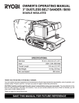
Fresh Water Flush Valve
Intake Service Valve
Brine Discharge Service Valve
Run
Run
Run
Off
Product Service Valve
Run
Off
Service
SPECTRA
Product Flow
Sausalito, California Phone (415) 332-3780 Fax (415) 332-8527
www.spectrawatermakers.com
Intake Service
Hose Connection
Brine Discharge Service
Hose Connection
Santa Cruz
Feed Pressure
Pressure relief valve is on the Clark pump. Open 1/2 turn.
Product Service
Tube Connection
Basic Operation:
Priming
Open pressure relief valve. Run the feed pump until feed pressure rises amd stablizes. If the system has two feed pumps,
prime pumps separately. Feed pressure will jump when the Clark pump "shifts".
Purging
If system has been stored, open pressure relief valve and run for 20 minutes. Attach the product service tube and lead to a container.
Set product service valve to "Service" position, close pressure relief valve and run for another 20 minutes. Discard product water.
Startup
Close pressure relief valve, if open. Check that the intake, flush, and discharge service valves are in the "Run" position. Set product service
valve to "Service" position and connect service tube. Start system. After two minutes, test product with the salinity sensor or taste. When
good product is detected, switch product service valve to "Run". Monitor feed pressure for pre-filter condition. Service pre-filter if feed
pressure is higher than normal. Refer to owner's manual for normal feed pressures.
Normal Operation/Fresh Water Flush
For best performance; run system to fill tanks then flush. To flush; while running pressurized, move the flush valve to "Flush" position.
Watch for the feed pressure to drop and stablize at a lower pressure, wait 30 seconds, then shut down. Re-flush or run within 1 week.
Storage
Attach service hoses to unit and lead to a clean container. If not already flushed, do a normal start up then fresh water flush the system.
Open the pressure relief valve. With system running in flush mode, set the brine discharge valve to "Service" position and divert 1.5
gallons of flush water into the container. Shut down the system and set the flush valve to "Run" position. Mix one container of SC-1 into
the flush water. Set intake, discharge, and product service valves to "Service" position. Run for 10 minutes, recirculating the solution,
then set the brine discharge valve to "Run" and empty container. Shut down system, return all service valves to "Run" position. Service
strainer and pre-filters; reinstall dry. Purge system on next start up.
5 Micron Pre-filter
Flush Water Charcoal Pre-filter
SANTA CRUZ
OPERATION AND INSTALLATION
MANUAL
Spectra Watermakers
A Division of Edinger Marine Service, Inc.
REVISED 11/24/19
298 Harbor Drive Sausalito CA 94965
Phone 415.332.3780
Fax 415.332.8527
E-mail: [email protected]
www.spectrawatermakers.com
page 1
Introduction
Thank you for choosing a Spectra Watermaker! It is our wish for you to be
completely satisfied with our product. We have inspected and tested all of the components
before shipping, and feel we have produced one of the finest products available.
Your long term satisfaction with this system will depend greatly on how the Spectra
system is installed. The unique performance is obtained not only by our new pressurization
process, but by careful attention to reducing flow restriction, mechanical friction and
electrical resistance. All of this is affected by the final installation, and that is ultimately up
to you. By reading, understanding and following this manual, even if you are not doing the
installation yourself, we are confident you will be happy with your new Spectra system.
With years of experience installing and repairing many different kinds of
watermakers, we have seen nearly everything that should or should not be done. This
manual includes the summation of that knowledge, tailored for the Spectra Watermakers .
It is very important that you follow the instructions in this manual. They are
designed to help you "customize" the installation to your boat, while maintaining
performance. If any questions arise, please call us for help immediately. This is a unique
product so be careful of "experts," as they most likely will not have gone through the same
learning curve as we have during the development of the Spectra systems.
If someone else is installing the watermaker for you, review all aspects of the system
with them before the drilling and cutting begins. This will help avoid making mistakes. If
you have any doubts, please call us. We will be happy to help tailor the system to your
particular needs. As with any sophisticated device, there may be “bugs” or minor problems.
Please call us for consultation or advice before attempting to repair a new system.
"Use it or lose it" really does apply to watermakers, but we prefer "use it or pickle it".
All watermakers will suffer damage if they are run and left without storage treatment or
"pickling". We have found that if the pickling and cleaning processes are made easy there is
a higher probability of it happening. This is why we have included service valves in the
Installation Kit. Even though the system can work without them, they are very helpful in the
servicing of your system.
In conclusion, having an adequate and reliable watermaker can improve the quality of
life on board more than almost any other piece of equipment. It is our sincere desire that you
will be able to take full advantage of your new Spectra Watermaker, confirming that you
have indeed made the best choice! And don’t forget to tell all your friends!
Thank you from all of us at Spectra Watermakers.
page 2
Table of Contents
System and Start-Up Log
page 4
Shipping and Shopping Lists
page 5
Features
page 7
Specifications
page 8
Component Description
page 9
Operating Procedures
page 12
Shutdown Procedures
page 15
Maintenance
page 17
Membrane Cleaning Procedures
page 18
Membrane replacement
page 20
Installation Basics
page 21
General Plumbing
page 22
Component Placement
page 24
Main Module Diagram
page 26
Clark Pump Diagram
page 27
Component Dimensions
page 28
Plumbing Diagram
page 29
Clark Pump Mounting Diagram
page 30
High Pressure Tube Instructions and Diagram
page 31
1/4” Tube Fitting Instructions Diagram
page 32
Clark Pump Mounting Template
page 33
Electrical
page 34
Wiring Diagram
page 35
Troubleshooting
page 36
Warranty
page 37
page 3
System and Start-Up Log
System Information
Model Number
________________
Serial Number
________________
Date Purchased
________________
Purchased From
____________________________
____________________________
____________________________
Installation Date
________________
Start-Up Performance Readings
Measure after 3 and 24 hours of pressurized run time in similar conditions.
3 hrs
Feed Water Temperature
__________
24 hrs
__________
Battery Voltage
__________
__________
Amperage Draw
__________
__________
Feed Pressure (psi)
__________
__________
Product Water Flow (gph)
__________
__________
page 4
Shipping List
Santa Cruz System
(1)
(1)
(1)
(1)
Operation and Installation Manual
Clark Pump
Membrane and Housing Assembly
Main Module including:
Pump and heat sink
Accumulator tank
Gauge and service valve panel
Manual fresh water backflush system
5 micron pre-filter
(1) Installation Kit Including:
Clark Pump mounting hardware
Membrane housing assembly mounts
Sea strainer
(10’) high pressure tube
50’ of 5/8” hose
25’ of 1/4” product tubing
Hose and tube fittings
Hose clamps
One container of SC-1 storage chemical
Hand held salinity monitor
Options
Clark Pump Mounting Bracket
Basic Cruise Kit
Includes six 5- micron filters, and two SC-1 storage chemical containers
Offshore Kit
Includes Clark pump seals, tools, two SC-2 cleaning chemical containers, and
overhaul instructions
Spare Feed Pump
Duel feed pump system for more output
Shopping List
page 5
In addition to the installation kit.
Refer to manual for wire size and type of fasteners
Fasteners/Hardware for mounting components to desired surfaces.
Marine grade duplex wire, connectors and wire ties with mounts.
One, 2 gallon minimum, plastic mixing container.
One 15 amp fuse or circuit breaker switch
Tools Required
Wrench set to 7/8”
Adjustable wrench
3/8” drill, drill index and a hole saw set
Screwdrivers
5/16” nut driver for hose clamps
Wire cutter
Wire stripper
Electrical crimping tool for insulated connectors
Features
The Spectra Santa Cruz integrates the Spectra 200-C into a compact three
module system that is the easiest of all our systems to install. It’s light weight,
compactness, low noise, and easy maintenance make it ideal for performance
page 6
sailing yachts. Powered by DC current, a generator set is not mandatory.
Using the patented Clark Pump and paying careful attention to system
efficiency, the Spectra Santa Cruz, operates on a fresh water to power ratio
that surpasses everything in the marine industry. The system makes an average
of 9 gallons per hour on 9 amps @ 12.5v DC, less than 13 watt hours per
gallon! That means that making one gallon of fresh water is like running only a
small DC cabin light for one hour!
The semi-modular design allows for easy installation. The feed pump,
pre-filter, gauges, fresh water flush, and service valves are mounted together on
a lightweight non-corrosive structure with an attractive gauge and service valve
panel that has basic instructions printed on it. The Clark Pump and the
membrane are mounted separately in any convenient location. The system’s
feed pump is self priming so the Spectra Santa Cruz can be up to 4 feet
above the water line!
The production of fresh water is stable through the system’s normal
operating sea water temperature and salinity range. Only the working pressures
change with the water conditions. A typical leading brand 200 gallon per day
unit running in 61 degree F water will only make 140 gallons per day. The
Spectra Santa Cruz will still be producing up to 200 gallons per day on a
fraction of the power.
A manual fresh water backflush system with a charcoal filter to protect
the membrane from chlorine and valve built into the panel is included standard.
Pressures are self-regulating, eliminating the need for adjustments, even
when operating in brackish waters. The feed pressure is limited to 125 psi.
A self priming multi-diaphragm feed pump is all that drives the system.
No additional boost pump is needed, or even helpful. A 5-micron pre-filter
assembly is provided standard for maximum system life and reduced filter
maintenance.
The system’s noise level is exceptionally low and unobtrusive, especially
compared to other systems of similar capacity. The feed pump has a smooth,
steady sound and almost no vibration.
An installation kit is included.
Spectra Santa Cruz Performance Specifications
Sea water temperature @ 50º F (10º C):
Voltage
12.5v
Feed flow
Feed pressure
High pressure
1.5 gpm (5.7 lpm)
76 psi (5.2 bar)
650 psi (44.2 bar)
page 7
Amperage
9.0
Product
8.0 gph (30.0 lph)
13.8v
14.4v
1.6 gpm (6.0 lpm)
1.7 gpm (6.4 lpm)
82 psi (5.6 bar)
84 psi (5.7 bar)
685 psi (46.6 bar)
700 psi (47.6 bar)
9.6
10.0
9.5 gph (35.2 lph)
10.0 gph (37.8 lph)
Sea water temperature @ 77º F (25º C):
Voltage
12.5v
13.8v
14.4v
Feed flow
1.5 gpm (5.7 lpm)
1.6 gpm (6.0 lpm)
1.7 gpm (6.4 lpm)
Feed pressure
High pressure
64 psi (4.3 bar)
68 psi (4.6 bar)
70 psi (4.8 bar)
550 psi (37.4 bar)
570 psi (38.8 bar)
580 psi (39.4 bar)
Amperage
8.0
8.5
8.8
Product
8.3 gph (31.4 lph)
9.3 gph (36.0 lph)
10.0 gph (37.8 lph)
Sea water temperature @ 90º F (32º C):
Voltage
12.5v
13.8v
14.4v
Feed flow
Feed pressure
High pressure
1.5 gpm (5.7 lpm)
1.6 gpm (6.0 lpm)
1.7 gpm (6.4 lpm)
64 psi (4.3 bar)
68 psi (4.6 bar)
70 psi (4.7 bar)
530 psi (36.0 bar)
550 psi (37.4 bar)
560 psi (38.0 bar)
Amperage
7.9
8.4
8.9
Product
8.5 gph (32.2 lph)
9.5 gph (35.9 lph)
10.3 gph (39.0 lph)
Sea water salinity @ 35,000 parts per million TDS
Salt rejection: 99.0% ~99.4% Typical purity test: < 400 mhos, 200 ppm, 99.4% pure
Performance Tolerance +/- 10%
Maximum Operating Temperature 113º F (45 degrees C)
System Specifications
Weights and Dimensions:
Clark Pump
Membrane
Main Module
Strainer
Hose & Fittings
Total weight
18.0 lbs. (8.18 kg)
13.0 lbs. (5.91 kg)
24.0 lbs. (10.9 kg)
.5 lbs. (0.23 kg)
3.5 lbs. (1.60 kg)
59.0 lbs. (26.82 kg)
27.25” (69.2 cm) L 8.25” (21.6 cm) H
6.5” (16.5 cm) D
43.5” (110.5 cm) L
3.5” (8.9 cm) Dia.
21.5” (53.9 cm) W 18.25” (46.4 cm) H
6.6” (12.8 cm) D
3.5” (8.9 cm) W
5” (12.7 cm) H
2.75” (7.3 cm) D
page 8
Component Description
Clark Pump
This is the heart of the system. The Clark Pump uses two opposing cylinders and
pistons that share a single rod through a center block. A reversing valve, controlled by a pilot
valve that is actuated by the pistons, allows the cylinders to alternate between driving and
pressurizing. Pressurization is achieved by the rod being driven into the other cylinder. As
the rod enters the cylinder, it pushes the piston which circulates the water out through the
membrane and back to the reversing valve. The valve directs the water back into the same
cylinder behind the piston, creating a closed loop. The rod displaces water as it enters the
cylinder, raising the pressure enough for reverse osmosis to occur in the membrane, thus fresh
water equal to the volume of the rod is produced on every stroke. The driving cylinder has
feed pressure pushing on the top of the piston which has ten times the surface area than in the
end of the rod. The water under the piston (brine) is discharged overboard. This gives the
piston a 10-to-1 advantage over the rod, allowing it to drive the rod into the pressurizing
cylinder. When the piston bottoms out on the center block, it actuates the pilot valve and the
process is instantly reversed. High efficiency is achieved because there is no "back stroke,"
allowing one cylinder to always be under pressure.
The speed of this process is determined by the water flow from the feed pump. The
feed pump has a nearly constant flow rate at a given voltage so the production of fresh water is
nearly constant, only the pressures change with changes in sea water temperature and salinity.
(see "Membrane" section)
A pressure relief valve and a reset button are incorporated in the Clark Pump to
depressurize the system for priming and service and resetting the reversing valve if the Clark
Pump is inadvertently stopped with the pilot and reversing valves at dead center.
Reverse Osmosis Membrane and Housing
The “RO” membrane element does the real work. A semi-permeable membrane and a
capillary layer are attached and wrapped around a center catch tube then encased in fiberglass.
The ends of the windings are open, allowing water to freely pass through from end to end. It
is installed into a high pressure housing that directs the pressurized salt water to flow through
the membrane and lets the product (fresh) water escape from the center catch tube. Threaded
ports are provided for hose connections in the end caps of the pressure housing.
Approximately 85 gph of high pressure salt water flows across the membrane layer as
8.5 gph of fresh water is forced through the membrane and lead by a capillary layer to the
catch tube. The excess salt water flowing out of the membrane is approximately 1/10th saltier
and is called “brine.” No salts are collected in the membrane. Membrane function is affected
by sea water temperatur e and salinity. The warmer or less salty the water, the easier it is for
the fresh water to pass through the membrane. This means that since the water production of
the Spectra systems are nearly constant, warmer water lowers the operating pressures. The
membrane is carefully sized to handle typical sea water temperatures and salinity, keeping the
pressures within limits.
Comp onent Description, cont.
page 9
Main Module
*The following 7 items are pre -installed in the Main Module
Note: The main module components are pre -plumbed and wired at the factory. All
installation plumbing connections are made to the outside. Main power wiring
connections are made to the terminal block at the top of the back panel. If further access
is needed, the face panel is removable. By removing the six mounting screws,
disconnecting the tube and hoses, the panel can be pulled clear .
*Feed Pump
The feed pump is simply a self priming, multi-diaphragm, pump designed to run at
pressures up to 125 psi. It is wired directly to the ships power through a 15 amp breaker or a
fuse and switch. The system can be run directly off charged batteries without having a charging
source running at the same time. Feed pressures average about 70 psi and the power draw
averages 8.5 amps per hour. The high pressure cut out switch are is factory set at 125 psi. The
optional duplex system allows for almost double the output. The second pump mounts where
the accumulator is and the accumulator is mounted separately.
*5 Micron Pre-filter
The pre- filter does the essential job of cleaning the sea water before it gets to the Clark
Pump and R.O. membrane. Replaceable pleated fiber filters are used. Filter maintenance is
crucial to the efficiency and life of the system. Five micron filtered sea water is important. A
reverse osmosis system running on 5 micron filtered water will last much longer than one
running on only 20 or 30 micron filtered water.
*Accumulator Tank
The accumulator tank is an air chamber divided by a rubber diaphragm. The top
chamber is pressurized with air to 10 psi below the expected feed pressure. For example, if the
feed pressure is 70 psi, the tank should be pressurized to 60 psi when the system is off. When
running, feed water will enter the lower chamber until the pressures equalize. Its function
resembles a cushion to smooth out the feed pressure spikes when the Clark Pump “shifts.” This
will extend the life of the feed pump and quiet the shifts between strokes.
*Feed Pressure Gauge
The feed pressure gauge is an indicator of system operational status. Higher than normal
pressures indicates the need for pre- filter service.
*Product Water Flow Meter
The product water flow meter indicates the flow in gallons per hour. The reading is
taken at the middle of the indicator ball.
Component Description, cont.
*Service Valves
The service valves are in the feed, brine discharge, and product lines to provide easy
page 10
access for proper maintenance. The service hoses attach to the panel face and are lead to a
cleaning container. IMPORTANT: The intake and discharge service valves will close off
all the ports if the lever is moved to the “Off” position. The product service valve cannot
close the ports when the lever is moved half way. This precludes the possibility of blocking the
product flow and causing an over pressure condition that could burst the tube.
*Manual Fresh Water Backflush System
The manual fresh water backflush system allows the operator to flush the system of salt
water before it is shut down. The system incorporates a charcoal filter to remove chlorine
when fresh water is drawn from the tank and a three way valve in the panel. When flushing is
desired, the valve is turned to let charcoal filtered fresh water into the feed system and the feed
pressure is watched for a pressure drop. When the feed pressure drops and stabilizes the system
can be shut down. Replace the charcoal filter every 6 months.
The pressure relief valve does not have to be opened during flushing because the
Spectra’s unique high pressure system will not generate membrane damaging excessive product
flow when brackish or fresh water is introduced into a pressurized system.
Sea Water Strainer
The strainer filters the salt water to the feed pump. It has a cleanable, fine mesh,
stainless steel element. The filter mesh is sized to stop debris that could jam in the pump’s
check valves. A coarse strainer should not be substituted.
Installation Kit
The installation kit includes 50 feet of 5/8” reinforced non-toxic feed and discharge
hoses, 10 feet of 1/2” high pressure tubing, 25 feet of 1/4” plastic product water tubing,
standard mounting brackets, and all of the required fittings and hose clamps for most
installations.
Mounting Bracket (optional)
The mounting bracket is a powder-coated aluminum “L” bracket for easy bulkhead
mounting of the Clark Pump. Two brackets can be used for overhead mounting.
Basic Cruise Kit (optional)
The kit includes three 20- micron and three 5- micron filters and the SC-1 storage and
scale cleaning compound (pickling) for 2 storage procedures.
Offshore Kit (optional)
The kit includes all seals and o-rings, composite valve sleeves, field tools and rebuild
instructions for the Clark Pump and the SC-2 alkaline membrane cleaning chemical compound.
Operating Procedures
New System Start-Up
Caution: Avoid running the system if the vessel is in contaminated water, such as in a harbor or
page 11
canal. Membrane damage and pre-filter clogging may result. Move the vessel to cleaner water.
If the boat cannot be moved, first run the system with the fresh water flush valve on “flush”and
the pressure relief valve open for 30 minutes. Close the pressure relief valve and continue
flushing for another 30 minutes with the product water diverted. This will flush the storage
solution from the membrane. Add water to the ships tank if necessary. The system can now be
run using a clean source of sea water in the cleaning container. Unchlorinated fresh water mixed
with sea salt can also be used. Use the intake, brine, and product service hoses to recirculate the
salt water to and from the container.
1. Check battery voltage. A nominal 12.8 VDC to 14.4 VDC should be indicated.
2. Confirm that the intake thru-hull is open and the strainer is clear.
3. Have the intake and brine discharge service valves in the normal run position and the
product service valve in the “Service” position. Direct the product service tube to a container
or into the bilge.
4. To prime the system, open the pressure relief valve on the panel face 1/2 turn and start the
feed pump. Listen for the feed pump to prime itself and the Clark Pump start to “shift.” Check
the brine discharge for water flow. Check the feed pressure, about 15-20 psi should be
indicated between shifts with the pump running and the system unpressurized.
5. Check the feed pump high pressure cut out switch set point. With the system primed and
running unpressurized, block the brine flow by moving the brine discharge service valve lever
to the “Off” position. This will stop the water flow and cause the feed pump to shut off. Check
the feed pressure gauge, it should be holding steady at about 115 to 125 psi. The pressure can
be adjusted by tightening (higher pressure) or loosening (lower pressure) the Allen head set
screw on the pump switch using a 5/64” Allen wrench. The accumulator tank will have to be
moved for access. Now is a good time to check for leaks in the feed and brine connections as
they are now pressurized to maximum.
6. Run the system unpressurized for 30 minutes after start-up to purge the pickling solution in a
new membrane.
7. Close the pressure relief valve to pressurize the system and watch for the feed pressure to
rise. Re-check the whole system for leaks, especially the high pressure hose connections. If
any are found, turn off the system and repair them before continuing. Run the system under
pressure for at least one hour while rejecting the product water. Compare the voltage, feed
pressure, water temperature and amp draw to the specification table. The feed pressure should
not spike more than 5 to 10 lbs. over normal when the Clark Pump shifts and should stay under
85 psi at all times. The feed pump should never be allowed to cycle the high pressure cut out
switch on and off during the shift. The pump sound should remain almost steady. If the
pressure spikes are high and/or the pump stops momentarily dur ing the shift, check the high
pressure cut out set point and/or check the accumulator pre-charge.
Operating Procedures, cont.
8. After one hour, test the product product water with the salinity monitor and taste. If the
water is good, the service valve can now be switched the “Run” position to direct the flow to
the water tank.
9. At three hours of pressurized run time, and again at 24 hours, re-check for leaks and take
note of the system feed pressure, product flow and amp draw, compare them to the
page 12
specification page and enter them into the start up log.
Normal Start-Up
1. For normal start-up (meaning the unit has been run within the last 3 days) move the product
valve to the “service” position to divert the product and start the system. Close the pressure
relief valve if it is open.
2. If air is in the system and the feed pump has lost its prime, open the pressure relief valve to
allow the feed pump to re-prime itself. Check for air leaks in the feed hose to the pump.
3. After starting and pressurizing the unit, check for leaks and wait for it to stabilize, then
check for proper readings (see Specifications, page 8 ). Air in the system will cause erratic
shifts and readings until it is purged out of the system. This may take up to 10 minutes.
4. Check the product water with the hand held salinity monitor or taste test. If good, switch the
product service valve to the “run” position to start filling the tanks.
Warning!
On start up, if the feed pressure keeps rising until the feed pump shut off and the Clark
Pump is not shifting, depressurize the system and press the reset button on the side of the
reversing valve on the Clark Pump, all the way in, to unstall the system. To avoid a stall
condition, always turn off the system right after the Clark Pump “shifts”. Also check that
the service valves are in the normal run position.
Pickled System Start-Up
If the system has biocide in it (also known as “pickling” or storage solution), open the
pressure relief valve 1/2 turn. Attach the product service line and lead to a container or into the
bilge. Switch the product service valve to the “Service” position to manually reject any
product water and run the system unpressurized for 30 minutes to purge the biocide. Close the
pressure relief valve to pressurize the system. Run for another 30 minutes, test the water, then
switch the product service valve back to the “Run” position.
Unknown Condition Start-Up (CAUTION: Do not start the system yet!)
If the system has been left unpickled for an extended length of time or the history is
unknown, perform this simple test before running the system:
Open the pre- filter and inspect its condition. If the filter is black and smell bad, that’s
one indication that the system is fouled. Install a new or cleaned pre- filter. Attach the brine
discharge service hose and place it into a container and move the brine discharge service valve
to the “Service” position. Open the pressure relief valve and start the system. Watch the brine
Operating Procedures, cont.
that first comes out. If the water is discolored and smells bad, perform an SC-2 cleaning on the
system before pressurizing (see cleaning instructions). Pressurizing a system with a fouled
membrane will compact the biological growth into the membrane and make it harder to clean.
If the water is only slightly discolored and smells OK, perform a Pickled System Start Up.
Compare the system readings to the performance specifications to see if the system is
performing properly.
Normal Operation
page 13
Spectra Watermakers are designed to run continuously with only pre- filter
maintenance performed as necessary. Ideal performance is achieved by running the system
until the tanks are full, do a fresh water flush, then turn off the system,
In moderate climates, if the membrane is mounted in a cool place, it is not necessary to
flush the system every time if the unit is used once every one to two days. Flush the system if
it’s not going to be operated for more than two days and up to one week. Flush the system after
every use in hot conditions. Pickle the system if longer periods of non-operation are expected.
Running the unit during charging cycles will produce more water because of the higher
voltage (see Performance Specifications). System readings should be periodically checked and
compared to the start-up log readings and performance specifications. Look for asymmetrical
readings and listen for any change in the sound of the system that may indicate potential
problems.
If too much air is introduced into the system when the system is running and
pressurized, the feed pump will cavitate and water flow will stop. This will not damage the
system. Open the pressure relief valve and reprime the feed pump.
All reverse osmosis watermakers are affected by water temperature and salinity. The
Spectra operating pressures will rise with colder temperatures and/or higher salinity, and fall
with warmer temperatures and/or lower salinity, but the product flow is affected very little.
page 14
Shutdown Procedures
When not in use, biological growth in the membrane is the leading cause of membrane
fouling. A warm environment will cause faster growth than a cold environment. The
following procedures assume a warm environment, such as in the Tropics.
Normal Shutdown,
Run system to fill the tanks. Check system for normal operation, then with the system running,
move the flush valve to the “flush” position. Watch for the feed pressure to drop and restabilize, wait 30 seconds and then shut down the system. When turning off the system, listen
for the Clark Pump to “shift” then immediately turn off the power. There is a small chance that
the Clark Pump will be left in a stalled condition if it is shut down during a “shift”. Service the
pre-filters and strainer if necessary. In moderate climates, the system can be left unflushed for
one to two days. In hot conditions, flush the system after each use.
On the next start up, if the Clark Pump is found to be stalled, turn off the system, open
the pressure relief valve, and push the reset button on the right side of the reversing valve in
completely, then restart. It is good practice to close the intake thru-hull after use.
Storage Shutdown or "Pickling,"
The Spectra SC-1 Storage and Cleaning chemical is specially
formulated to be able to clean mineral scale and be used as a system
preservative. Sodium bisulfite or metabisulfite should not be used as a
preservative in the Spectra systems. Use of sodium bisulfite will attack
materials used in the Spectra systems and void the warranty.
The SC-1 Storage and Scale Cleaning Compound has to be mixed at 1 Spectra container to
3 gallons of fresh water to have the proper solution. An average of 1.5 gallons of water is
in the Spectra system. This water has to be figured in the mixture
1. Attach the service hoses to the face of the unit and direct them to at least a 2 gallon clean
plastic or SS mixing container. Run the system normally and then flush. When the flush is
complete but before the system is shut down, move the brine discharge valve to the “service”
position and collect (1.5) gallons of fresh flush water through the discharge service hose into
the container. Turn off the system and open the pressure relief valve 1/2 turn.
2.
Mix one container of the SC-1 into the cleaning container. Re-check that the pressure
relief valve is open. Turn the intake and brine discharge valves to the “Service” position then
run the system for 10 minutes. Do not run the system pressurized with pickling solution in
it. Light discoloring of the solution is acceptable.
Do not let skin, eyes, or lungs have any contact with the storage and cleaning
chemical.
If the solution becomes excessively discolored, mineral scale and live biological
growth may be present and membrane cleaning is recommended. Refer to the
membrane cleaning section for further instructions.
Shutdown procedures cont.
3. After 10 minutes, turn the brine discharge valve to the “Run” position. When the container
page 15
is empty, shut off the system.
4. Close the intake thru-hull and turn the intake service valve back to the “Run” position. If
the system shares an intake thru- hull, move the intake service valve lever to the “Off” position.
This will close off all ports and isolate the watermaker.
5. Remove and clean the sea water strainer screen and pre- filters. Reassemble dry.
6. When returning the system to service after pickling, check that the intake thru-hull open and
service valves are in the “Run” positio n. Run unpressurized for at least 30 minutes to purge
the system. Manually discard the product water for another 30 minutes after pressurizing.
7.
To winterize, Open the pressure relief valve and flush 5 gallons of potable water system
antifreeze through the system instead of using the normal SC-1 storage procedures.
page 16
Maintenance
The Seawater Strainer
The sea water strainer’s stainless steel element should be inspected, removed and
cleaned as needed. Be careful to ensure that the thru-hull is closed before disassembly and the
seal and element are in place on reassembly. When the system is put into storage, remove, rinse
and reassemble dry to impede corrosion. Check frequently during operation.
The Micron Pre-filter
Service the pre-filter when the feed pressure is about 5 psi over normal for the
conditions. The easiest way to service the filter is to first shut off the thru-hull, open the
housing, discard the old filter, remove the O-ring to avoid loosing it, and clean the housing.
Reinstall the O-ring and reassemble the pre- filter with a new 5- micron filter element. Leave
dry until the next start- up.
Used pleated elements can be carefully cleaned if they are not too compacted. Do not
use full pressure from a garden hose or scrub with a hard brush on the pleats. Gently spray the
outside with water and then plug one end with your hand, filling from the other end to flush
from the inside. Be careful to not distort the pleats. Another way is to tow them behind the
boat until clean, 4 knots maximum. Slip a line through the filter and tie a stopper knot.
Elements that show any signs of deterioration should be replaced. Check for leaks on the first
run after a filter service.
The Charcoal Backflush Filter
Replace the charcoal filter element every 6 months.
The Membrane
The membrane needs to be cleaned only when it has lost up to 10% of its capacity due
to fouling or the product quality degrades. The leading cause of fouling is from biological
growth that occurs when the system is left unused for long periods without flushing or pickling.
Fouling from mineral scaling can happen under certain sea water conditions, and from rust.
Poor tasting water and/or higher than normal pressures and amp draw for the sea water
temperature and salinity conditions are the main indicators of membrane fouling. Other
conditions can cause high pressure (such as in very cold water). Low product flow is usually
due to low voltage or a clogged pre- filter. Look for all other causes before cleaning the
membrane.
There are two types of cleaners; acid and alkaline. The acid cleaner (SC-1) will remove
mineral scaling and kill live microbes and is also used for storage. The alkaline cleaner (SC-2)
is used to remove biological by-products, oil, and dirt particles that get past the pre-filters. If
membrane performance is reduced and has not been pickled recently, cleaning with both
chemicals is recommended. The acid cleaner should be used first. The acid cleaner is also used
as the storage solution so scale is automatically reduced when the system is “pickled”. If
biological growth is suspected, the alkaline cleaner can be used on the next start up after the
unit has been pickled.
If the membrane fails to respond to both cleanings, this is an indication of another
problem with the system, or that it is time to replace the membrane. Call Spectra
Watermakers before removing a membrane.
page 17
Membrane Cleaning
For normal cleaning, the SC-1 Storage and Cleaning Compound is used first, then the
SC-2 Alkaline Cleaning Compound. If the unit has been “pickled” recently with the SC-1
solution then some cleaning has already occurred, so use the SC-2 first. If the membrane does
not respond to the SC-2 use the SC-1, following the normal cleaning procedures. Using hot
water, 120º, is highly recommended as it greatly enhances the ability of the cleaners to do there
jobs.
If the history of the system is unknown or has been left “unpickled” for an extended
length of time and biological growth is present, it is recommended that the system is cleaned
with the SC-2, using an alternate source of unchlorinated fresh water before the system is run
under pressure. A simple test can be performed to see if biological growth has occurred:
Before running the system, remove the pre-filter and examine its condition. If the housing is
full of discolored smelly water, the system was not properly stored. Install clean pre- filters if
they were bad. Next check the membrane. Attach the brine discharge service hose and lead it to
a container. Open the pressure relief valve 1/2 turn and turn the brine discharge service valve to
the “Service” position. Run the system for one minute. Examine the brine water; if it’s
discolored and smells bad, perform a SC-2 cleaning with an alternate sour ce of unchlorinated
water before running the system pressurized. If the brine is fairly clean, the system can be run
normally and checked for performance. Clean the membrane only if its performance is reduced.
Cleaning Procedures
Note: procedures are the same for the SC-1 and SC-2 cleaners
The SC-1 and SC-2 Cleaning Compounds have to be mixed at 1 Spectra container to 3
gallons of fresh water to have the proper solution. Do not mix yet! An average of 1.5
gallons of water is in the Santa Cruz system. This water has to be figured in the mixture.
The cleaning solution needs to be heated to 120º F. A stainless steel pot and a hot plate
instead of the cleaning bucket is one way. An accurate thermometer is necessary. Do not
let the solution get over 135º F!
1. Attach the service hoses to the face of the unit and direct them to the container. Move the
fresh water flush valve to the “flush” position. Start the system and allow it to flush for 4
minutes. Move the brine discharge valve to the “service” position. Allow 1.5 gallons of
discharge water into the container then turn off the system. Do not use tap water or
chlorinated water! Distilled or charcoal filtered water is acceptable if using the flush water is
not an option.
3. IMPORTANT! open the pressure relief valve one half turn. Mix 1 Spectra chemical
container into the fresh water in the container Do not let skin, eyes, or lungs have any contact
with the storage and cleaning chemical.
3. Place the intake, brine discharge, and product service valves in the “Service” position. Start
heating the water.
4. Run the system unpressurized for one hour while maintaining the solution at 120º F, then
turn off for one hour to let the membrane soak. Run the system again for 1 hour while heating
the solution, then turn off for one hour. Do not let the water get above 135º F!
Membrane cleaning, cont.
page 18
5. Turn the brine discharge service valve to the “Run” position, and run the system until the
container is empty.
6. Place the intake service valve to the “Run” position. Run the system unpressurized for at
least 30 minutes to purge the cleaning solution.
7. After purging, close the pressure relief valve to pressurize the system. Manually divert the
product water with the product service valve into the cleaning container. After 30 minutes,
check the feed pressure, product flow, and quality, to determine if the membrane is functioning
normally. If the cleaning solution became very discolored during the cleaning process, it is
recommended to repeat the process. If the alkaline cleaning did not affect the membrane
enough, repeat the cleaning process using the acid cleaner. Always manually reject the product
water for 30 minutes after cleaning.
8. If the membrane performance is still poor and no other problem can be found, contact
Spectra Watermakers for further assistance.
page 19
Membrane Element Replacement
Do not remove the membrane from the housing unless absolutely necessary.
Troubleshoot for all other causes of poor performance and try the recommend procedures first.
Caution: membranes must be kept wet to prevent permanent damage.
Disassembly:
Disconnect the high pressure tubes, cut the housing mount bands, and move the
membrane housing to a work area that can handle water spillage. Clean off any deposits on the
ends with a stiff brush and fresh water. Note which end goes where so they can be reinstalled
the same way later.
Loosen the retainer rings with an adjustable deck fill fitting wrench or use a hard plastic
or wood punch and a mallet on the slot provided. As the retainer rings unscrew, twist and pull
the end fittings to follow the rings out. This way they can be removed with the factory
plumbing fittings in place. By first removing the plumbing fittings, the rings can be removed
and then the end plugs removed from the housing. Inspect the end plugs and O-rings for
damage, replace if necessary.
Push the membrane element out of the housing by first pushing on the outlet end. If it
resists, try pushing on the other end. If the membrane is going to be kept for any reason, seal it
in plastic before it dries out. Do not open the new membrane packaging until ready to install.
Assembly:
Install the inlet end plug first. Lubricate the O-rings and the housing with soap or with a
very thin layer of a pure silicone lubricant and start threading on the ring end plug assembly.
As the end fitting O-ring comes into contact with the housing, twist and push on the end fitting
to properly insert the O-ring, then continue tightening the retainer ring. If the tube fittings were
removed, lubricate and insert the end plug then install the retainer ring and the plumbing
fittings. Check that the new element has a brine seal on one end only. Lubric ate the element
brine seal and wet the whole inside of the housing. Insert the brine seal end of the element into
the outlet end of the housing. A gentle push with a slight rocking motion and help with fingers
should compress the brine seal lip so it slips inside. Push the element into the housing, the
brine seal will give some resistance, until it completely engages the inlet end plug. The element
product catch tube engaging and passing through the small O-rings can be felt. The element
brine seal should now be next to the inlet plug.
Install the outlet end plug the same way as the inlet. It will go in harder because of the
product tube O-ring engaging the element.
A new membrane has a pickling solution in it and should be thoroughly flushed before
use. Follow the new system start up procedures.
Open the pressure relief valve 1/2 turn and start the system. Look for leaks at the end
plugs. If a large leak is present, the large O-ring around the end plug is not seated properly and
the end plug will have to be removed and redone. After flushing, close the relief valve and
check system for proper operation.
page 20
Installation Basics
The Spectra Watermakers are designed for energy efficiency. All aspects of the
system have been optimized for this goal, therefore any changes in the basic layout or
components will most likely reduce this efficiency. The overall length of the feed, discharge
and high pressure hoses have little effect on performance and can even help smooth out the
Clark Pump shift pulses but that every hose bend or 90 degree fitting absorbs power. Avoid
adding 90 degree fittings. Use gentle hose bends where possible. A good installation will be a
proper compromise between minimum hose and wire runs, accessibility, environment and
esthetics.
Thru-hulls
It is recommended that a designated 3/4” intake thru- hull and seacock be installed for
the system as far below the water line as possible. A protruding scoop type is preferred for high
speed hulls. Sharing a thru-hull with another system is acceptable, but can introduce
unforeseen problems such as intermittent flow restriction, air bubbles and contaminates. If the
system is sharing an intake thru- hull, the intake service valve can be used to shut off water to
the system. For racing boats a retractable snorkel type thru-hull fitting is preferred to be able to
pick up water away from the hull.
Do not install the intake close to or down stream of a head discharge. Install as far
below the water line and as close to center line as possible to avoid contamination and air
induction.
We recommend that a reputable boatyard install any underwater thru- hulls.
The discharge thru-hull should be mounted above the waterline, in or just above the boot
stripe to minimize water lift. Having the discharge feed into a cockpit or sink drain will work,
but can make an unpleasant gurgle sound.
Double clamp all hose connections below the water line if possible.
Fittings
Pipe fittings that are to thread into plastic should be coated with at least 3 wraps of
Teflon tape. To avoid cracking the plastic, tighten until only 1/2 of the threads are buried. This
may not seem tight, but they will not, and should not, bottom out like a metal to metal
connection.
Metal to metal pipe connections should have 1-1/2 to 2 Teflon wraps only.
Be very careful to avoid getting any tape over the end of the fitting that might get into
page 21
the system. To insure this does not happen, leave the very first thread uncoated.
General Plumbing
Follow the Clark Pump and Plumbing Diagrams on pages 26, 27, and 29 for hose and
tube connections. All feed and discharge hoses are made of 5/8" reinforced nylon. The high
pressure 1/2” tubing is connected with tube to pipe SS compression fittings. The 90 degree
high pressure SS tube fittings mounted in the high pressure inlet and outlet on the Clark Pump
can be rotated up too 1/2 turn for better tube runs. Straight SS tube fittings can also be used.
The product water lines are 1/4" black plastic tubing with connectors. Feed water operating
pressure up to 125 psi requires vigorous hose clamp tightening. It is recommended to lubricate
the clamp screw and use a nut driver for the final tightening. Re-tighten all hose clamps and
check for leaks after the first few hours of running.
If you use feed hose or product tubing that is not supplied by Spectra Watermakers , it
is mandatory to use products with a minimum burst pressure of 250 psi. If other types of prefilter housings are used, they need to rated at 125 psi minimum working pressure.
Feed and Discharge Hoses
Route the 5/8" hose smoothly from the intake thru- hull to the strainer, main module,
Clark pump, back to the main module, and then to the discharge thru-hull. Use straight hose
fittings and gentle turns in the hose where possible. Minimum hose bend radius is 6”. Tightly
secure hoses with tie wraps to avoid chafe.
Main Module Plumbing
The sea water intake hose connects to the hose barb in the upper port of the intake
service valve. The feed water hose to the Clark Pump connects to the hose barb next to the
accumulator tank. The brine discharge hose from the Clark Pump connects to the hose barb
attached to the back port of the brine discharge valve. The brine discharge hose to the through
hull connects to the hose barb in the front port of the brine discharge valve. The product tube
from the membrane connects to the fitting at the bottom of the product flow meter. The product
tube to the tank connects to the fitting in the top port of the product service valve. The fresh
water flush hose runs from a tee installed in the feed line from the water tank to the hose barb
on the flush filter.
High Pressure Tubes
Be sure to follow the Clark Pump and Plumbing Diagrams for proper connection
between the Clark Pump and the membrane housing. Membrane water flow direction is marked
on the housing. Rotate the 90 degree high pressure tube fittings on the Clark Pump for ideal
tube runs. The high pressure tubes are usually made in place. Loosely route the tubes between
the Clark pump and the membrane and cut long. Minimum tube bend radius is 6”. Follow the
tube connection instructions on page 31. Connect the tubes to one of the components, secure
the tube runs, and then trim and connect to the other component. A 90 degree bend in a hose is
better than a 90 degree fitting. A tube, when mounted, should have at least one gentle bend to
allow for expansion. Do not connect a tube straight between hard mounted fittings. When
connecting the tubes to the components, be sure to hold fitting body during the final tightening.
page 22
General Plumbing, cont.
If other than the Spectra supplied high pressure tube and fittings are used, they need
to be at least 1/2" ID if hose, 1/2” OD if tube, with non-ferrous 1/2” high pressure fittings,
and have a working pressure of at least 2000 psi.
Product Water Tubing
The product water lines are 1/4" plastic tubing. Minimum tube bend radius is 3.”
Connection can be made to either end of the membrane housing. Refer to the tube fitting
assembly diagram on page 32.
IMPORTANT: The product water flow should not be
restricted in any way. If the line gets blocked, the pressure will build until the line fails.
Restricting the flow will reduce efficiency and may cause damage to the membrane.
Connect to the water tank at or near the top. The ideal spots are to tee into the tank vent line or
the fill hose. Do not tap into the bottom of the tank or a water feed manifold. Air can be pulled
through the membrane and affect the domestic water system.
Fresh water flush system
Install a tee into the feed line from the water tank to the ships water pressure pump inlet.
Use the 5/8” feed hose to connect from the tee to the charcoal flush filter.
Fittings
Pipe fittings that are to thread into plastic should be coated with at least 3 wraps of
Teflon tape. To avoid cracking the plastic, tighten until only 1/2 of the threads are buried. This
may not seem tight, but they will no t, and should not, bottom out like a metal to metal
connection.
Metal to metal pipe connections should have 1-1/2 to 2 Teflon wraps only. Be very
careful to avoid getting any tape over the end of the fitting that might get into the system. To
insure this does not happen, leave the very first thread uncoated.
page 23
Component Placement
Refer to the Dimension & Plumbing Diagrams on pages 26 to 29
Main Pump and Control Module
The main pump module is designed to mount on a vertical surface. The feed pump level
can be up to 4’ above the waterline. Locate in an area that allows easy access to the face panel
and the service hoses can reach a container placed in a spot where water spillage is acceptable.
Allow for a minimum of 2” of clearance on the sides and top. Use the unit itself as a template
for drilling the mounting bolt holes. Use quarter inch bolts or lag screws with washers. If lag
bolts are used they must thread into at least 1” of solid material. Drill pilot holes for lags bolts.
If necessary additional mounting holes can be easily drilled into the back panel.
Clark Pump
Refer to the the Clark Pump Mounting Diagram on page 30 to install the mounting
brackets and shock mounts. Bolt the mounting brackets to the base of the center block with the
short 5/16” SS bolts and washers, sandwiching the plastic washers in between the center block
and the brackets. The brackets will over hang from the front and back of the center block.
Moisten the rubber shock mounts and slip them into the bracket holes then install the plastic
inserts.
The Clark Pump can be mounted on any horizontal surface that will support it’s weight
and is not subjected to excessive vibration. Height above or below the water line is
unrestricted. Mounting on a vertical surface can be expedited by using the optional "L" mount
bracket. For hanging from overhead, use two of the "L" brackets. Avoid mounting in the
middle of a large unsupported flat surface that could amplify the sound of the pump shift. The
Clark Pump can be mounted in any position if it is hard mounted without using the brackets.
More noise may be transferred to the vessel.
Allow room in the front and back for access to the high pressure tubes and hose
connections. If the space behind the unit is restricted, attach the high pressure tubes to the
Clark Pump before final mounting. The 90 degree fittings supplied are acceptable for the feed
and high pressure tube connections to the unit and can be rotated for easy tube runs. Straight
fittings can also be used. The brine discharge hose connection to the reversing valve body
should be straight if possible, and can be connected to either end of the reversing valve. Plug
the unused port.
Make sure that the area around and under the pump does not have any water sensitive
equipment. Water will be spilled during any repairs or if a leak occurs.
Use the Clark Pump mounting hole layout, see page 33, to measure and drill for the
fasteners. 1/4" bolts and Nylock nuts are preferred, but lag bolts are acceptable if they penetrate
at least 1" into solid material. Drill pilot holes for lags bolts.
Caution: Tighten the fasteners until there is medium pressure on the plastic
inserts. The plastic inserts will collapse if over tightened. The 1/4” fender washer must be on
top to prevent the mounting brackets from slipping out of the rubber mounts under adverse
conditions.
Do not mount the Clark Pump in an area that is subject to sustained temperatures over
120 degrees F.
page 24
Component Placement, cont.
Membrane and Housing Assembly
Mount the membrane and housing assembly as close to the Clark Pump and in as
cool a place as possible. Use the black plastic brackets and heavy duty black tie wraps
provided. The plastic tie wraps allow the membrane housing to expand and contract with
pressure changes without damage. Mount the membrane preferably at or below the level of
the valve body on the Clark Pump to help purge air. It is OK to mount the membrane above
the Clark Pump, but keep it as close as possible. The membrane housing is marked for water
flow direction and can be mounted at an angle or vertical, but the brine outlet end should be
up to help purge air. Route the high pressure tubing to and from the membrane housing as
smoothly as possible. Avoid clamping the tubes tightly to any surfaces for sound
dampening. "Hanging" the tubes away from a surface with wire ties so that they are neither
tight nor completely loose is best.
The product water tube can be connected to either end of the membrane. Plug the
unused product port and re-label.
Do not mount the membrane in an area that is subject to sustained temperatures over
120 degrees F.
Sea Water Strainer
Mount the sea water strainer between the intake thru-hull valve and the main module
in a protected, accessible and visible spot that is not above water sensitive equipment.
Secure it with the black plastic mount and tie provided. Allow a minimum of 1-1/2" space
below for the strainer bowl removal. Note the direction of flow on the housing and mount to
minimize hose lengths and bends.
Accumulator Tank
When the Santa Cruz is ordered with the duplex feed pump option the accumulator is
mounted separately from the main module. Mount it in any convenient spot, at any
orientation, plumbed between the pre-filter and the Clark Pump.
page 25
Santa Cruz Main Module
page 26
Run
Feed Pressure
Run
Basic Operation:
Santa Cruz
Flush Water Charcoal Pre-filter
Run
Brine Discharge Service
Hose Connection
Off
Brine Discharge Service Valve
Run
Product Service
Tube Connection
Service
Product Service Valve
5 Micron Pre-filter
Storage
Attach service hoses to unit and lead to a clean container. If not already flushed, do a normal start up then fresh water flush the system.
Open the pressure relief valve. With system running in flush mode, set the brine discharge valve to "Service" position and divert 1.5
gallons of flush water into the container. Shut down the system and set the flush valve to "Run" position. Mix one container of SC-1 into
the flush water. Set intake, discharge, and product service valves to "Service" position. Run for 10 minutes, recirculating the solution,
then set the brine discharge valve to "Run" and empty container. Shut down system, return all service valves to "Run" position. Service
strainer and pre-filters; reinstall dry. Purge system on next start up.
Normal Operation/Fresh Water Flush
For best performance; run system to fill tanks then flush. To flush; while running pressurized, move the flush valve to "Flush" position.
Watch for the feed pressure to drop and stablize at a lower pressure, wait 30 seconds, then shut down. Re-flush or run within 1 week.
Sausalito, California Phone (415) 332-3780 Fax (415) 332-8527
www.spectrawatermakers.com
SPECTRA
Fresh Water Flush Valve
Priming
Open pressure relief valve. Run the feed pump until feed pressure rises amd stablizes. If the system has two feed pumps,
prime pumps separately. Feed pressure will jump when the Clark pump "shifts".
Purging
If system has been stored, open pressure relief valve and run for 20 minutes. Attach the product service tube and lead to a container.
Set product service valve to "Service" position, close pressure relief valve and run for another 20 minutes. Discard product water.
Startup
Close pressure relief valve, if open. Check that the intake, flush, and discharge service valves are in the "Run" position. Set product service
valve to "Service" position and connect service tube. Start system. After two minutes, test product with the salinity sensor or taste. When
good product is detected, switch product service valve to "Run". Monitor feed pressure for pre-filter condition. Service pre-filter if feed
pressure is higher than normal. Refer to owner's manual for normal feed pressures.
Pressure relief valve is on the Clark pump. Open 1/2 turn.
Intake Service
Hose Connection
Off
Intake Service Valve
Product Flow
End block B
High pressure port for remote
pressure relief valve
Valve block
End block A
Composite cylinder
and base
Brine out
Pressure relief valve
Center block
Feed in
Stainless steel tube
Cylinder ring
Clark Pump
End Cap
Front View
End block A
High pressure port for remote
pressure relief valve
Valve block
End block B
Reset button
Composite cylinder
and base
Alternate brine out
High pressure in
Test port
Center block
High pressure out
Stainless steel tube
Cylinder ring
End cap
Clark Pump
page 27
Back View
Run
Feed Pressure
Run
Basic Operation:
Santa Cruz
Sausalito, California Phone (415) 332-3780 Fax (415) 332-8527
www.spectrawatermakers.com
Flush Water Charcoal Pre-filter
Run
Brine Discharge Service
Hose Connection
Off
Brine Discharge Service Valve
Run
Product Service
Tube Connection
Service
Product Service Valve
5 Micron Pre-filter
Storage
Attach service hoses to unit and lead to a clean container. If not already flushed, do a normal start up then fresh water flush the system.
Open the pressure relief valve. With system running in flush mode, set the brine discharge valve to "Service" position and divert 1.5
gallons of flush water into the container. Shut down the system and set the flush valve to "Run" position. Mix one container of SC-1 into
the flush water. Set intake, discharge, and product service valves to "Service" position. Run for 10 minutes, recirculating the solution,
then set the brine discharge valve to "Run" and empty container. Shut down system, return all service valves to "Run" position. Service
strainer and pre-filters; reinstall dry. Purge system on next start up.
Normal Operation/Fresh Water Flush
For best performance; run system to fill tanks then flush. To flush; while running pressurized, move the flush valve to "Flush" position.
Watch for the feed pressure to drop and stablize at a lower pressure, wait 30 seconds, then shut down. Re-flush or run within 1 week.
SPECTRA
Fresh Water Flush Valve
Priming
Open pressure relief valve. Run the feed pump until feed pressure rises amd stablizes. If the system has two feed pumps,
prime pumps separately. Feed pressure will jump when the Clark pump "shifts".
Purging
If system has been stored, open pressure relief valve and run for 20 minutes. Attach the product service tube and lead to a container.
Set product service valve to "Service" position, close pressure relief valve and run for another 20 minutes. Discard product water.
Startup
Close pressure relief valve, if open. Check that the intake, flush, and discharge service valves are in the "Run" position. Set product service
valve to "Service" position and connect service tube. Start system. After two minutes, test product with the salinity sensor or taste. When
good product is detected, switch product service valve to "Run". Monitor feed pressure for pre-filter condition. Service pre-filter if feed
pressure is higher than normal. Refer to owner's manual for normal feed pressures.
Pressure relief valve is on the Clark pump. Open 1/2 turn.
Intake Service
Hose Connection
Off
Intake Service Valve
27 1/4"(69.3cm)
SPECTRA
21 1/4"(53.9cm)
Clark Pump
Product Flow
(112.5cm)
(46.4cm)
43 1/2"
18 1/4"
6 5/8"
(16.8cm)
(13.3cm)
5 1/4"
Sea strainer
(8.9cm)
3 1/2"
6.5" (16.4cm) with fittings
(8.9cm)
3 1/2"
8 1/2"
5"
Membrane and Housing
(21.6cm)
(7.3cm)
2 7/8"
(12.7cm)
page 28
1 1/2"
(3.8cm)
page 29
Sea water
intake hose
Intake
Service hoses
Strainer
Cleaning
container
Fresh water
from tank
1/2" H.P. tube from bottom H.P. outlet
High pressure
inlet
Off
Flush Water Charcoal Pre-filter
Feed Pressure
Run
Back
Santa Cruz
Sausalito, California Phone (415) 332-3780 Fax (415) 332-8527
www.spectrawatermakers.com
SPECTRA
Fresh Water Flush Valve
Run
Off
Brine Discharge Service Valve
5 Micron Pre-filter
Service
Product Service Valve
Run
Front
Product Flow
Brine discharge hose
Vent
Brine discharge
hose
Fresh water tank
1/4" Product
tube
Brine outlet
Product outlet
1/2" H.P. tube to top H.P. inlet
Santa Cruz Plumbing Diagram
Feed water hose
Run
Intake Service Valve
Membrane and housing
Lag or screw
mounting
Bolt mounting
1/4" SS Bolt
2"-1/4" SS Lag bolt or
# 14 sheet metal screw
Caution: Do not over tighten,
the plastic inserts may crush.
1/4" SS
Fender Washer
Plastic Insert
Rubber
Grommet
Center Block
1/4" SS
Fender Washer
Plastic Insert
Plastic washers
Rubber
Grommet
5/16"-3/4"
Mount Bolts
Pre-Drill
Mounting Surface
Plastic washers
Bottom view
Aluminum
brackets
Note: Remove aluminum
mounts before shipping the
Clark Pump.
Clark Pump Mounting
page 30
Spectra High Pressure Tube Fitting Assembly
Carefully fit and measure the tubing before cutting with a sharp razor knife or ho se
cutter and remove any burrs. Minimum tubing bend radius is 6”. Route tubing away from
excessive heat sources and secure from vibration and chafe. Have at least one shallow bend in
a tube assembly after it is installed.
Refer to figure 1. If a fitting has been dissembled, reassemble as illustrated. The notch
on the ferrule must engage the inside of the nut properly for the nut to seat down fully. Once
the tube is inserted the ferrule and nut will naturally align.
Refer to figure 2. Insert tube fully into the fitting, it should go in 0.9”. Tighten the nut
finger tight while moving the tube around to prevent binding. One thread should be showing
under the nut. Secure the tube so it won’t back out when tightening.
Refer to figure 3. Use 13/16” wrench to hold a straight body fitting or a 3/4” wrench
for a 90º body, and a 7/8” wrench for the nut. Hold the body, recheck the tube insertion, then
tighten the nut 1-2/3 turns (10 flats) after a good finger tight. Use the index mark on the nut as
a guide. The threads should be completely covered by the nut.
The tube connectors can be disconnected and re-tighten several times. To reconnect,
insert the tube and ferrule into the body then hand tighten the nut. Hold the body and tighten
the nut with a wrench a little past where resistance is encountered. When correct, the nut
should be tightened a little past where it was before disassembly. Always check for leaks.
Index mark
Straight thread
Figure 1.
Ferrule
Nut
Body
Cut tube square
Figure 2.
Black high pressure tubing
Tighten 1-2/3 turns (10 flats) with
a 7/8" wrench after finger tight.
Use index mark as guide
Figure 3.
Insert tube 0.9" until it stops
page 31
No threads showing
Body
Step 1:
O-ring
Spacer
Grab Ring
Nut
Tubing
Dissemble fitting components
1/2" max
Step 2:
Step 3: Gently fit the tube into the body and loosely thread on the nut.
Step 4: Push the tube into the body until it bottoms out then hand tighten the nut.
DO NOT OVER TIGHTEN!
1/4" Tube Fitting Assembly
page 32
page 33
4.000"
Under
Cylinder
Front
Caution! NOT DRAWN TO SCALE
Clark Pump
Mounting layout
Back
6.500"
Under
Cylinder
Drill for 1/4" bolts,
1/4" lags,
# 14 SM Screws
ELECTRICAL
See the wiring diagram on the following page.
A robust electrical connection is crucial to the proper operation of the system.
Examine your electrical system carefully to determine the proper place from which to draw
power. If power will be drawn from a breaker on the main distribution panel, make sure the
panel has at least #8 gauge wire for panel positive feed and ground. Check all connections
for tightness, including the ground buss. Refer to the wiring diagrams on page 35.
If the panel is inadequate or too far away, a direct connection to a battery is possible.
An in-line fuse (15 amp-slow blow) next to the battery and a switch (20 amp minimum
rating) will be necessary. For 24 VDC systems use a 7.5 amp breaker.
Main module wiring: For 12 VDC use a 15 amp breaker, 24 VDC use 7.5 amp
breaker. Wire from the power source to the module using #12 gauge to 10 feet, #10 gauge to
18 feet, and #8 gauge to 28 feet. For 24 VDC systems use a 15 amp breaker and #14 gauge
to 10 feet, #12 gauge to 18 feet, and #10 gauge to 28 feet.
Use marine grade insulated double-crimp connectors that match the wire gauge. Size
ring terminals to the size of the fasteners. Crimp the connectors with a crimper designed for
insulated connectors using both hands as hard as you can for the main crimp, and a little
easier for the insulation crimp. Pull on the connector to test the strength of the crimp, you
should not be able to pull it off. Heat shrink all connections where possible. Remember to
slip the heat shrink onto the wires before crimping.
Follow the pattern of the original factory wiring when adding a new circuit.
When adding a new wire to an existing wire bundle, remove all the old tie wraps where
possible, run the new wire, then tie at even intervals. This will result in a clean and
"original" look.
Connect the power wiring to the terminal block on the top of the back panel, + red, - black.
Troubleshooting Guide
page 34
page 35
+
_
To battery, #8 gauge or larger
Negtive buss
15 amp breakers 12VDC
7 amp 24VDC
Positive buss
Main Electrical Panel
Spectra Santa Cruz
Wiring Diagram
# 14 gauge to 10 feet
# 12 gauge to 18 feet
# 10 gauge to 28 feet
Wire size for each pump
24VDC
# 12 gauge to 10 feet
# 10 gauge to 18 feet
# 8 gauge to 28 feet
Wire size for each pump
12VDC
Cooling fan
Boost Pump
Optional Duplex Boost Pumps
Cooling fans
For
instructions
on
repairing
SYMPTOM
the
Clark
Pump,
please
CAUSE
contact
Spectra
Watermakers.
REMEDY
*Feed pump start but shuts down on *Clark Pump stalled.
high pressure. (over 100 psi)
*Brine service valve in mid (off)
position
*Pre-filters excessively clogged
*Push in reset button
*Open brine service valve
*System does not run
*Tripped breaker or blown fuse.
*Pump power relay faulty.
*Motor burned out.
*Check wiring to motor.
*Replace relay.
*Replace motor.
*Feed pump runs but no fresh
water flow.
*Thru-hull closed.
*Pressure relief valves open.
*Pump air-locked.
*Check system, then open thru-hull.
*Close relief valves.
*Open relief valve to purge air,
then close.
*Service pre-filters
*Lower water production, high amp *Pre-filter clogged.
draw, high feed pressure.
*Service pre-filters.
*Low water production, normal to *Relief valve partially open.
low amp draw, normal to low feed *Leak in high pressure hoses or
pressure.
fittings.
*Internal leakage in the Clark
Pump.
*Debris in feed pump check valves.
*Tighten hand tight only.
*Tighten or replace fitting and/or
hose.
*See Clark Pump Repair Manual.
*Water production normal, feed
pressure high, high amp draw.
*Cold sea water temperature.
*Membrane starting to foul.
*Normal operation.
*Clean membrane.
*Water production normal, feed
pressure low, amp draw low.
*Warm sea water temperature.
*Normal operation.
*Water production high, poor
water quality.
*Seal failure inside membrane
housing.
*Membrane failure.
*Disassemble and check for bad
seals and/or corrosion.
*Replace membrane.
*Asymmetrical pressure and flow
readings between shifts.
*Reversing valve seal leaking.
*Shaft seal leaking.
*Pin seal leaking.
*Check valve leaking.
*Scored cylinder wall.
*Piston seal leaking.
*See Clark Pump Repair Manual.
page 36
*Disassemble pump head and
clean.
LIMITED WARRANTY
Spectra Watermakers warrants to the original purchaser that all components, except for the
Clark Pump, are free from any defects in material and/or workmanship for a period of one year
from the date of purchase.
Spectra Watermakers warrants to the original purchaser that the Clark Pump is free from
any defects in material and/or workmanship with a limited life time warranty from the date of
purchase.
If any such defect is discovered and reported within the warranty period, Spectra
Watermakers will repair or replace the affected component free of charge, subject to
verification of the defect or malfunction upon inspection at Spectra Watermakers. The
customer is responsible for all costs incurred for removal, shipping to and from our facility, and
reinstallation.
This warranty does not apply to malfunctions or physical damage resulting from abuse, neglect,
accident, alteration, modification, feed pump substitution, submersion, shipping damage, hoses
and fittings not supplied by Spectra Watermakers , improper membrane maintenance, oil and
chlorine damage, use of sodium bisulfite or sodium metabisulfite, or improper installation.
Consumables such as pre- filter elements are not covered.
Spectra Watermakers , under no circumstances, shall be liable for any consequential damages
arising out of, or in any way connected with, the failure of the product to perform as set forth
herein. This limited warranty is in lieu of any and all other expressed or implied warranties.
Spectra Watermakers reserves the right to make changes or improvements on its products
without incurring the obligation to retrofit such changes or improvements on previously
manufactured units.
If a possible warranty problem is detected, please contact one of our service representatives
before any disassembly for assistance, and to receive a Return Authorization number if a
component is to be returned for a warranty repair.
Proof of purchase, return address, and a Return Authorization number are required for all
warranty repairs.
Ship to:
Spectra Watermakers
298 Harbor Drive Sausalito, CA 94965
Phone 415.332.3780
Fax 415.332.8527
E-mail: [email protected]
page 37