1
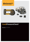
Solar Module
Installation Manual
www.canadian-solar.com
Installation Manual
GENERAL INFORMATION
This is the general installation, maintenance and use manual for the CS-Series Solar Modules. The word "module"
or "PV module" as used in this manual refers to one or more CS-Series Solar Modules. This manual provides
important safety information regarding the installation, maintenance and use of the modules that the user and the
professional installer should read carefully and follow. Failure to follow these instructions may result in death, bodily
injury or damage to property. The installation of solar modules requires specialized skills and should only be
performed by qualified, licensed professionals. Please retain this manual for future reference.
DISCLAIMER OF WARRANTIES
The information contained in this manual is subject to change by Canadian Solar Inc. without prior notice. Canadian
Solar Inc. makes no warranty of any kind whatsoever, either expressed or implied, with respect to the information
contained herein. If any representations and warranties are made by Canadian Solar Inc. regarding the modules,
such representations and warranties shall be included in a separate, written purchase agreement for the modules.
LIMITATION OF LIABILITY
Canadian Solar Inc. shall not be liable in damages, of whatever kind, as a result of the reliance on or use of the
information contained herein.
OWNERSHIP
This manual is the proprietary property of Canadian Solar Inc. No part of this manual may be reproduced or copied
without the express written permission of Canadian Solar Inc. Any unauthorized use of this manual or its contents is
strictly prohibited. No license is granted by implication or under any patent or patent rights. Any and all intellectual
property rights in or related to the PV modules are and shall remain the property of Canadian Solar Inc. All rights are
expressly reserved.
SAFETY PRECAUTIONS
Warning: All instructions should be read and understood before attempting to install, wire, operate
and/or maintain the module. Module interconnects pass direct current (DC) when the module is
exposed to sunlight or other light sources. Contact with electrically active parts of the module, such
as terminals, can result in injury or death, whether the module is connected or disconnected. To the
maximum extent permitted by applicable law, the installer assumes the risk of all personal injury or
property damage that might occur during the installation and handling of modules.
General safety
Do not connect or disconnect modules when current from the modules or an external source is present.
Cover the front of the modules in the PV array with an opaque material to halt production of electricity when
installing or working with a module or wiring.Wear suitable protection (non-slip gloves, clothes, etc.) to prevent
direct contact with 30V DC or greater.
All installations must be performed in compliance with all applicable regional and local codes such as, the latest
National Electrical Code (USA) or Canadian Electric Code (Canada) or other national or international electrical
standards.
There are no user serviceable parts within the PV module. Do not attempt to repair any part of the module.
Do not disassemble the module or remove any part installed by the manufacturer.
Remove all metallic jewellery prior to installing this product to reduce the chance of accidental exposure to live
circuits.
Use electrical insulated tools to reduce your risk of electronic shock.
If the front glass is broken, or the back sheet is torn, contact with any module surface or the frame can cause electric
shock.
Do not install or handle the modules when they are wet or during periods of high wind.
Do not use or install broken modules.
Do not artificially concentrate sunlight on a module.
Keep the junction box cover closed at all times.
2
SV\662830.2
EN-Rev 1.1 Copyright
2009 Canadian Solar Inc.
Installation Manual
MECHANICAL / ELECTRICAL SPECIFICATIONS
Under certain conditions, a module may produce more current or voltage than its Standard Test Conditions (STC)
rated power. Accordingly, a module's open-circuit voltage and short-circuit current at STC should be multiplied by 1.25
when determining component ratings and capacities. An additional 1.25 multiplier for a short-circuit current (for a total
of 1.56), and a correction factor for an open circuit (see Table 1 below) for sizing conductors and fuses is applicable, as
described in section 690-8 of U.S. NEC.
Lowest Expected Ambient Temperature
Correction Factor
( / )
25 t o 10 / 7 7 to 5 0
1.05
9 to 0 / 4 9 to 3 2
1.10
-1 to 10 / 31 to 14
1.15
-11 to 20 / 13 to -4
1.20
-21 to 40 / -5 to -40
1.30
Table 1. Low Temperature Correction Factors Table for Open-Circuit Voltage
Table 2 presents the electrical and mechanical characteristics of Canadian Solar Inc. crystalline silicon PV modules,
and the major electrical characteristics at STC appear on each module label.
Model Number
CS4C-90
CS4C-100
CS4D-30
CS4D-40
CS4D-50
CS4D-60
CS5A-150
CS5A-155
CS5A-160
CS5A-165
CS5A-170
CS5A-175
CS5A-180
CS5A-185
CS5A-190
CS5B-130
CS5B-140
CS5B-150
CS5B-160
CS5B-170
CS5B-180
CS5B-190
CS5C-75
CS5C-80
CS5C-85
CS5C-90
CS5C-95
CS5E-13
CS5E-14
CS5E-15
CS5E-18
EN-Rev 1.1 Copyright
Open Circuit Short Circuit Operating Current at Rated Rated Power
Voltage(Voc) Current(Isc) Voltage Operating Voltage
(Pmax)
<V>
<A>
(Vmp) <V>
(Imp) <A>
<W>
43.2
43.2
21.6
21.6
21.6
21.6
43.2
43.4
43.6
43.8
44.1
44.3
44.5
44.7
44.9
43.2
43.2
43.2
43.2
43.2
43.2
43.2
21.6
21.8
22
22.2
22.5
21.3
21.3
21.4
21.5
2009 Canadian Solar Inc.
2.85
3.2
1.94
2.58
3.2
3.79
4.74
4.86
4.97
5.08
5.19
5.29
5.40
5.50
5.60
4.11
4.42
4.74
5.06
5.38
5.7
6.02
4.74
4.97
5.19
5.40
5.60
0.87
0.92
0.97
1.15
34.4
34.4
17.2
17.2
17.2
17.2
34.8
34.8
34.9
35.2
35.5
35.8
36.1
36.4
36.6
34.4
34.4
34.4
34.4
34.4
34.4
34.4
17.4
17.5
17.7
18
18.3
17.2
17.2
17.3
17.4
SV\662830.2
2.62
2.92
1.75
2.33
3
3.49
4.31
4.45
4.58
4.69
4.79
4.89
4.99
5.09
5.18
3.78
4.07
4.36
4.66
4.95
5.24
5.52
4.31
4.58
4.79
4.99
5.18
0.76
0.81
0.87
1.04
90
100
30
40
50
60
150
155
160
165
170
175
180
185
190
130
140
150
160
170
180
190
75
80
85
90
95
13
14
15
18
Overall
Dimension
<mm>
Weight
<Kg>
1320X664X40 10.5
1006X454X35
7
1595X801X40 15.5
1302X923X40
16
1213X547X35
8
620
284
25
2.5
3
Installation Manual
Model Number
CS5E-20
CS5E-22
CS5F-8
CS5F-10
CS5F-12
CS5F-13
CS5F-14
CS5F-15
CS5P-200
CS5P-205
CS5P-210
CS5P-215
CS5P-220
CS5P-225
CS5P-230
CS5P-235
CS5P-240
CS5P-245
CS5P-250
CS6A-140
CS6A-145
CS6A-150
CS6A-155
CS6A-160
CS6A-165
CS6A-170
CS6A-175
CS6A-180
CS6A-185
CS6A-190
CS6A-195
CS6C-105
CS6C-110
CS6C-115
CS6C-120
CS6C-125
CS6C-130
CS6C-135
CS6C-140
CS6C-145
CS6D-55
CS6D-60
CS6D-65
CS6D-70
CS6P-175
CS6P-180
CS6P-185
CS6P-190
CS6P-195
CS6P-200
CS6P-205
CS6P-210
CS6P-215
4
Open Circuit Short Circuit Operating Current at Rated Rated Power
Voltage(Voc) Current(Isc) Voltage Operating Voltage
(Pmax)
<V>
<A>
(Vmp) <V>
(Imp) <A>
<W>
21.8
22.1
21.3
21.4
21.5
21.5
21.8
22
57.4
57.6
57.9
58.1
58.4
58.6
58.8
59.1
59.3
59.6
59.8
28.7
28.8
28.8
28.8
28.9
29
29.2
29.3
29.4
29.5
29.6
29.6
21.5
21.6
21.6
21.7
21.8
22
22
22.1
22.2
21.6
21.7
22
22.1
35.9
35.9
36
36
36.1
36.2
36.2
36.4
36.5
1.24
1.33
0.54
0.66
0.78
0.83
0.88
0.92
4.78
4.86
4.94
5.02
5.10
5.18
5.25
5.33
5.40
5.47
5.54
6.72
6.92
7.12
7.32
7.51
7.69
7.85
8.03
8.20
8.37
8.54
8.72
6.74
7.01
7.28
7.52
7.75
7.96
8.20
8.42
8.65
3.45
3.72
3.96
4.21
6.80
6.98
7.16
7.33
7.51
7.68
7.80
7.91
8.01
17.5
17.7
17.2
17.3
17.3
17.4
17.5
17.8
46.4
46.5
46.6
46.7
46.9
47.2
47.5
47.8
48.1
48.4
48.7
23
23
23.1
23.1
23.1
23.1
23.2
23.4
23.6
24
24.2
24.4
17.3
17.3
17.3
17.3
17.4
17.5
17.7
18
18.3
17.3
17.4
17.6
18
28.7
28.7
28.8
28.8
28.8
28.9
28.9
28.9
29
SV\662830.2
1.15
1.24
0.47
0.58
0.69
0.75
0.80
0.84
4.31
4.41
4.51
4.61
4.69
4.76
4.84
4.92
4.99
5.06
5.14
6.08
6.29
6.50
6.71
6.92
7.13
7.33
7.49
7.62
7.71
7.84
7.98
6.08
6.36
6.64
6.92
7.20
7.43
7.62
7.76
7.93
3.18
3.46
3.70
3.88
6.10
6.26
6.43
6.60
6.76
6.93
7.10
7.26
7.43
20
22
8
10
12
13
14
15
200
205
210
215
220
225
230
235
240
245
250
140
145
150
155
160
165
170
175
180
185
190
195
105
110
115
120
125
130
135
140
145
55
60
65
70
175
180
185
190
195
200
205
210
215
Overall
Dimension
<mm>
Weight
<Kg>
446 X284 X 25
1.6
1602X1061X40
20
1324X982X40
16
1485X666X40
12
783X666X35
12
1638X982X40
20
EN-Rev 1.1 Copyright
2009 Canadian Solar Inc.
Installation Manual
Model Number
CS6P-220
CS6P-225
CS6P-230
CS6P-235
CS6P-240
CS6P-245
Open Circuit Short Circuit Operating Current at Rated Rated Power
Voltage(Voc) Current(Isc) Voltage Operating Voltage
(Pmax)
<V>
<A>
(Vmp) <V>
(Imp) <A>
<W>
36.6
36.7
36.8
36.9
37
37
8.09
8.19
8.34
8.47
8.61
8.75
29.3
29.5
29.8
30.1
30.4
30.7
7.52
7.63
7.71
7.82
7.91
7.99
Overall
Dimension
<mm>
Weight
<Kg>
220
225
230
235
240
245
Table 2. Specifications for CS-series photovoltaic modules.
Standard Test Conditions are: irradiance of 1 kW/m 2, AM 1.5 spectrum, and cell temperature of 25 . Pmax, Voc and
Isc of any individual module will be 2.5% of these specified values. Specifications are subject to change without
notice.
UNPACKING THE MODULES AND STORAGE
Precautions and General Safety
The utmost care is required when handling the modules. Be careful when unpacking, transporting and storing the
modules.
Do not allow children and unauthorized persons near the installation site or storage area of modules.
Do not transport modules in an upright position.
Carry a module by its frame with two or more people. Do not use the connection cables as handles.
Do not drop or place objects on the modules (such as tools.)
Do not carry a module by its wires or junction box.
Ensure modules do not bow under their own weight.
Do not stand on, step on, or scratch the modules.
Do not place modules on top of each other.
Do not subject the modules to load.
Do not mark the modules using sharp implements.
Never leave a module unsupported or unsecured.
Do not change the wiring of bypass diodes.
Keep all electrical contacts clean and dry.
If it is necessary to store the modules temporarily, a dry, ventilated room should be used.
INSTALLING THE MODULES
Precautions and General Safety
Before installing modules, contact the appropriate authorities to determine permissions, installation and inspection
requirements to follow that apply to your site and installation.
Check applicable building codes to ensure that the construction or structure (roof, facade, support, etc.) where the
modules are being installed has enough strength.
When installing the modules, please ensure the assembly is mounted over a fire resistant roof covering rated for the
application and required a slope less than 5in/ft (127mm/305mm) to maintain a fire class rating.
Environmental conditions
The module is intended for use in general open climates, as defined in IEC 60721-2-1: Classification of
environmental conditions Part 2-1: Environmental conditions appearing in nature - temperature and humidity.
EN-Rev 1.1 Copyright
2009 Canadian Solar Inc.
SV\662830.2
5
Installation Manual
The module must not be installed in the proximity of highly flammable gases and vapours (e.g., filling stations, gas
containers, paint equipment).
The module must not be installed near naked flames or flammable materials.
Do not expose modules to artificially concentrated light sources.
The module must not be immersed in water (either fresh or salt) or constantly be exposed to water (either fresh or salt)
(i.e. from fountains, sea spray).
If there is exposure to salt (i.e., marine environments) and sulphur (i.e., sulphur sources, volcanoes); there is a risk
of corrosion.
Requirements of installation
Ensure that the module meets the technical requirements of the system as a whole.
Ensure that other systems components do not exert damaging mechanical or electrical influences on the modules.
Modules can be wired in a series to increase voltage or in parallel to increase current. To connect in series, connect
cables from the positive terminal of one module to the negative terminal of the next module. To connect in parallel,
connect cables from the positive terminal of one module to the positive terminal on the next module.
Quantity of bypass diodes provided can vary depending on model series.
Connect the quantity of modules that match the voltage specifications of the inverters used in the system. The
modules must not be connected together to create a voltage higher than the permitted system voltage.
In order to avoid (or minimize) mismatch effects in arrays, it is recommended that similar electrical performance of
modules should be connected in same series.
The recommended maximum series fuse rating is tabulated in table 2.
To minimize risk in the event of an indirect lightning strike, avoid forming loops when designing the system.
Modules should be firmly fixed in place in a manner suitable to withstand all expected loads, including wind and
snow loads.
Precipitation can run out through small openings on the underside of the module. Make sure that these openings are
not obstructed after mounting.
Optimum orientation and tilt
To achieve the maximum annual yield, determine the optimum orientation and tilt of the PV modules. Generation of
maximum power occurs when sunlight shines perpendicularly onto the PV modules.
Avoid shading
Even the slightest partial shading (e.g., from dirt deposits) will cause a reduction in yield. A module is considered
"shadow-free" if it is unobstructed across its entire surface for the whole year. Even on the shortest day of the year,
unobstructed sunlight can reach the module.
Reliable ventilation
Sufficient clearance between the module frame and the mounting surface is required to allow cooling air to circulate
around the back of the module. This also allows any condensation or moisture to dissipate. Clearance of 1/4 of an inch
or more between modules is required to allow for thermal expansion of the frames.
Grounding
Although the modules are certified to safety class II, it is recommended that they be grounded. Ensure to comply with
all local electrical codes and regulations.
The earth grounding connection should be made by a qualified electrician.
Connect module frames to each other using cables with cable lugs. Holes provided for this purpose are identified
with a green label. Use a serrated washer or a self-tapping screw to create the conductive connection.
All the junctions on the conductive connection must be fixed. Metal containing iron in the conductive connection
should be treated against corrosion by anodization, spray-painting, or galvanization to prevent rusting and corrosion.
Stainless steel does not need to be treated.
MOUNTING INSTRUCTIONS
Modules should be bolted to support structures through mounting holes located in the frame's back flanges only
(see Example A). Do not drill additional holes. Doing so will void the warranty. Each module must be securely fastened
at a minimum of 4 points. If additional wind or snow loads are anticipated for This installation, additional mounting
points should be used. System designer and installer are responsible for load calculations and for proper design of
support structure.
Use appropriate corrosion-proof fastening materials.
6
SV\662830.2
EN-Rev 1.1 Copyright
2009 Canadian Solar Inc.
Installation Manual
Top or bottom clamping methods will vary (see Example B) and are dependent on the mounting structures. Follow
mounting guidelines recommended by the PV mounting supplier.
The mounting design must be certified by a registered professional engineer. The mounting design and procedures
shall comply with local codes and all authorities having jurisdiction.
Example A:
Bolting
Example B:
Clamping on
Use a torque wrench for installation. The above figure shows methods of fastening module to support structure.
In Example B, the tightening torque (using stainless steel M8 bolts) is 17 Nm.
MODULE WIRING
Correct wiring scheme
When designing the system, avoid forming loops (to minimize risk in the event of an indirect lighting strike). Check
that wiring is correct before starting up the system. If the measured open circuit voltage (V oc) and short-circuit current
(I sc) differ from the specifications, then there is a wiring fault.
Correct connection of plug connectors
Make sure that the connection is safe and tight. The plug connector should not receive outer stress. The connector
should only be used to connect the circuit. It should never be used to turn the circuit on and off.
Use of suitable materials
Use special solar cable. Wiring should be placed in conduit that is sunlight-resistant or, if exposed, should be
sunlight-resistant type UF cable, 8-14 AWG (9-3mm ), 90 wet rated in accordance with local fire, building and
electrical code) and suitable plugs only. Ensure that they are in perfect electrical and mechanical condition. Use only
single-wire cables. Select a suitable conductor gauge to minimize voltage drop.
Cable protection
Secure the cables to the mounting system using UV-resistant cable ties. Protect exposed cables from damage
using suitable precautions (e.g. locate them within plastic conduit). Avoid exposure to direct sunlight.
MAINTENANCE
Do not change the PV components (diode, junction box, plug connectors).
Regular maintenance is required to keep modules clear of snow, bird droppings, seeds, pollen, leaves, branches,
dust and dirt spots.
Given a sufficient tilt (at least 15o), it is not generally necessary to clean the modules (rainfall will have a selfcleaning effect). When there is a noticeable buildup of soiling deposits on the module surface, wash the PV array
using water without cleaning agents and a gentle cleaning implement (a sponge), during the cool of the day. Dirt
must never be scraped or rubbed away when dry, as this will cause micro-scratches.
If snow is present, a brush with soft bristles can be used to clean the surface of the module.
Periodically inspect the system to make sure all wiring and supports stay intact.
If you need electrical or mechanical inspection or maintenance, it is recommended to have a licensed, authorized
professional carry out the inspection or maintenance to avoid hazards of electric shock or injury.
EN-Rev 1.1 Copyright
2009 Canadian Solar Inc.
SV\662830.2
7
Headquarters
650 Riverbend Drive, Suite B, Kitchener, Ontario, Canada N2K 3S2
Tel: +1-519-954-2057 Fax: +1-519-954-2597
Email: [email protected]
Europe
Mozartstrasse 1, 87727 Babenhausen, Germany
Tel: +49 (0) 8333 - 92328 - 0
Fax: +49 (0) 8333 - 92328 - 11
Email: [email protected]
USA
12657 Alcosta Blvd, Suite 140, San Ramon, CA 94583
Tel: +1-925-866-2700 Fax: +1-925-866-2704
Email: [email protected]
Korea
201, SK HUB Officetel, 708-26, Yeoksam-Dong, Kangnam-gu, Seoul, Korea
Tel: (02) 539-7541 Fax: (02) 539-7505
Email: [email protected]
China
199 Lushan Road, Suzhou New District, Jiangsu, China, 215129
Tel: +86 (512) 6690-8088
Email: [email protected]
Others: [email protected]