1
INNOVATION I QUALITY I VALUE
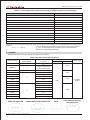
Table 1: Low temperature correction factors table for open-circuit voltage
Lowest Expected Ambient Temperature (℃/℉)
Correction Factor
24 to 20/76 to 68
1.02
19 to 15/67 to 59
1.04
14 to 10/58 to 50
1.06
9 to 5/49 to 41
1.08
4 to 0/40 to 32
1.10
-1 to-5/31 to 23
1.12
-6 to-10/22 to 14
1.14
-11 to-15/13 to 5
1.16
-16 to-20/4 to-4
1.18
-21 to-25/-5 to-13
1.20
-26 to-30/-14 to-22
1.21
-31 to-35/-23 to-31
1.23
-36 to-40/-32 to-40
1.25
Alternatively, a more accurate correction factor for the open-circuit voltage can be calculated based on the following
formula:
T is the lowest expected ambient temperature at the system location
C Voc=1- ∝Voc ×(25-T)
αVoc (%/℃) is the temperature coefficient of the selected module
(Refer to corresponding datasheet)
3.1 DIODES
·Diodes inside the junction box should meet requirements below:
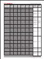
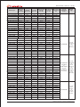
Table 2: By-pass diode specifications
Number of
bypass diodes
Number of cells
CS6P-PE
5
12
CS6A-PE
5
CS5P
4
Module series
by diodes
Diode ratings
Voltage
Current
Diode type
≥12 A
10 (for 3 substrings)
9 (for 2 substrings)
24
CS5A
24
CS5T
20
CS6A
3
CS6P
16
20
CS6X
24
CS6H
18
CS5C
18
CS6E
18
CS6D
2
CS6C
≥10A
≥40V
≥15 A
Schottky
diodes
≥10A
18
18
CS5E
18
CS5H
18
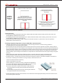
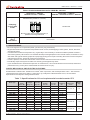
·Diode configurations as below:
CS6P-PE /CS6A-PE
EN-Rev 2.2 Copyright
CS5A/CS5T/CS6A/CS6P/CS6X
20 12 Apri. Canadian Solar Inc.
CS5P
CS6H/CS5C/CS6E/CS6D/
CS6C/CS5E/CS5H
2