1
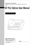
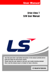
User Manual
RNet Option Board
SV-iS7 Series
* Use this board after read Safety Instruction of this manual carefully before
using and follow the instructions exactly.
* Please hand this user manual to end user and trouble shooting manager
* After read this manual, keep it at handy for future reference.
LS Industrial Systems
SV-iS7 RNet Manual
M
Before using the product, thank you for using our SV-iS7 RNet Option Board.
Safety Instruction
z
To prevent injury and danger in advance for safe and correct use of the product, be sure
to follow the Safety Instructions.
The instructions are divided as ‘WARNING’ and ‘CAUTION’ which mean as follow.
z
WARNING
This symbol indicates the possibility of death or
serious injury.
CAUTION
This symbol indicates the possibility of injury or
damage to property.
The meaning of each symbol in this manual and on your equipment is as follows.
z
This is the safety alert symbol.
This is the dangerous voltage alert symbol.
z
z
After reading the manual, keep it in the place that the user always can contact easily.
Before you proceed, be sure to read and become familiar with the safety precautions at
the beginning of this manual. If you have any questions, seek expert advice before you
proceed. Do not proceed if you are unsure of the safety precautions or any procedure.
2
SV-iS7 RNet Manual
WARNING
z Be cautious about dealing with CMOS elements of option board.
It can cause malfunction by static electricity.
z Connection changing like communication wire change must be done with power
off.
It can cause communication faulty or malfunction.
z Be sure to connect exactly between Inverter and option board.
It can cause communication faulty or malfunction.
z Check parameter unit when setting parameter.
It can cause communication faulty.
3
SV-iS7 RNet Manual
M
1. Introduction
RNet communication board makes the connection between PLC of LSIS and SV-iS7
inverter by a fast series communication so that PLC sequence program can control the
inverter by high speed communication operation of 1 Mbps. Controlling and monitoring
inverter by PLC sequence program makes it easier to install and modify the system.
A number of inverters can be connected by two communication lines so that saving
installation time through simple wiring and easy replacement can be possible. Using extra
devices of PLC and connecting with various systems including PC, the factory automation
can be easier.
2. Technical date for RNet communication board
Electric
4
Item
Specifications
Transmission Speed
1Mbps
Encoding type
Manchester Bi-phase-L
Frame synchronization type
Transmission distance
(*1:per segment)
Maximum 750m
Transmission distance
(If repeater is used)
Maximum 750m x (6 repeaters +1)
= 5.25km
Twisted pair shielded cable
RNet dedicated cable
Transmission route
Cable name: LIREV-AMESB 1φ
(PC 717 6705)
Manufacturer: LS Cable
Network
terminal resistance
Terminal 120.8ohm 1/2W
with an error range of 5%
Built-in RNet communication board
Maximum points per station
Master + Slave = 64 points
Master point : 0,Slave points :1~63
Maximum protocol size
256 bytes
Frame format
Field Bus standard
IEC TC65 / SC65C / WG6 65C 90.8
Access method to service zone
Token Passing
SV-iS7 RNet Manual
Item
Specifications
Communication type
Connection Oriented Service
Connectionless Service
Frame error check
CRC16
*1) Segment
It means local network connecting all stations using the same Token without using any
connecting devices (Gateway, EOC, and repeater).
3. RNet cable connection
Communication
terminal name
Description
TRX-
Communication signal terminal N
TRX+
Communication signal terminal P
SG
Shield/Signal Ground
TRX-
Communication signal terminal N
TRX+
Communication signal terminal P
9 Each two TRX-, TRX+ signals are connected in parallel.
9 When installed at terminal, if you turn on the 1 switch of RNet communication board,
terminal resistance of 120.8Ω, 1/2W is connected to communication signal terminal
(TRX- and TRX+).
9 Frame Ground is connected with inverter body. If inverter body is put to earth, SHIELD
line is to be connected to Frame Ground.
4. Product Constituents
-. RNet communication board: 1
-. RNet manual: 1
-. Fixed Screw (M3): 1
5
SV-iS7 RNet Manual
M
5. RNet communication board
Interior and appearance /Installation
(1) Interior
▶ SW1 : -. Pin 1 (terminal resistance connecting setting switch)
On : 120.8 Ohm terminal resistance connected.
-. Pin 2 ~ 4 (Not used)
(2) Appearance/Installation
RNet terminal
Inverter connection
LED Display
<RNet communication board appearance >
6
<RNet communication board installed
in IS7 inverter>
SV-iS7 RNet Manual
6. RNet LED Information
Four LEDs are installed in iS7 RNet communication board informing the user of present
RNet status. In iS7 RNet communication board, LED is located in the below turn.
Green
Green
Red
Green
TX
RX
Error
CPU
LED name
Color
Function
CPU
Green
ON (0.5sec On, 0.5sec OFF) – It shows that the power
is fed to RNet communication board and CPU is
operating normally.
TX
Green
TX Led is ON when inverter responds to the request of
PLC.
RX
Green
RX Led is ON when inverter receives the request of
PLC.
Be On with the same period of CPU – Displayed when
Option Trip occurs.
Option Trip is related with the CAN communication
interruption between RNet card and inverter.
Error
Red
Be On with the opposite period of CPU
– Network Configuration Error is displayed.
Network Configuration Error is related with setting as 0
the address point of inverter or when the setting of
Control Num of inverter is different from the Master.
7
SV-iS7 RNet Manual
M
7. RNet related Keypad Parameter
Code
CNF-30
Parameter name
Option Type-1
Initial value
-
Setting range
-
Description
RNet: display the type
of built-in
communication board
Keypad
Fx/Rx-1
DRV-06
Cmd Source
Fx/Rx-1
Fx/Rx-2
Int. 485
Operation
Source setting
FieldBus
PLC
Keypad-1
Keypad-2
V1
I1
DRV-07
Freq Ref Src
Keypad-1
V2
I2
Frequency
Source setting
Int. 485
Encoder
FieldBus
PLC
COM-06
FBus S/W Ver
-
-
Display the version
COM-07
FBus ID
1
0~63
Communication Station
address setting
Fixing the
communication speed
setting
COM-08
FBus BaudRate
1Mbps
1Mbps
COM-09
FBus Led
-
-
COM-30
ParaStatus Num
3
0~8
COM-31
Para Status-1
0x000A
0x0000 ~ 0xFFFF
Receiving Address 1
COM-32
Para Status-2
0x000E
0x0000 ~ 0xFFFF
Receiving Address 2
8
Communication
board LED Display
Receiving data number
SV-iS7 RNet Manual
Code
Parameter name
Initial value
Setting range
COM-33
Para Status-3
0x000F
0x0000 ~ 0xFFFF
Receiving Address 3
COM-34
Para Status-4
0x0000
0x0000 ~ 0xFFFF
Receiving Address 4
COM-35
Para Status-5
0x0000
0x0000 ~ 0xFFFF
Receiving Address 5
COM-36
Para Status-6
0x0000
0x0000 ~ 0xFFFF
Receiving Address 6
COM-37
Para Status-7
0x0000
0x0000 ~ 0xFFFF
Receiving Address 7
COM-38
Para Status-8
0x0000
0x0000 ~ 0xFFFF
Receiving Address 8
COM-50
Para Ctrl Num
2
0~8
COM-51
Para Control-1
0x0005
0x0000 ~ 0xFFFF
Transmitting Address 1
COM-52
Para Control-2
0x0006
0x0000 ~ 0xFFFF
Transmitting Address 2
COM-53
Para Control-3
0x0000
0x0000 ~ 0xFFFF
Transmitting Address 3
COM-54
Para Control-4
0x0000
0x0000 ~ 0xFFFF
Transmitting Address 4
COM-55
Para Control-5
0x0000
0x0000 ~ 0xFFFF
Transmitting Address 5
COM-56
Para Control-6
0x0000
0x0000 ~ 0xFFFF
Transmitting Address 6
COM-57
Para Control-7
0x0000
0x0000 ~ 0xFFFF
Transmitting Address 7
COM-58
Para Control-8
0x0000
0x0000 ~ 0xFFFF
Transmitting Address 8
None
PRT-12
Lost Cmd Mode
None
Free-Run
Dec
PRT-13
Lost Cmd Time
1.0 sec
0.1~120.0 sec
Description
Transmitting
number setting
data
Operation method when
losing
communication
command
Decision time of Lost
communication
command time
9
SV-iS7 RNet Manual
M
(1)
Option Type-1 (CNF-30)
– Display the type of communication board
9 Option Type-1 displays the type of communication card built-in inverter
9 If RNet communication board is installed properly and there is no error in RNet
communication board, “RNet” is displayed.
(2)
Cmd Source (DRV-06)
– Operation command Source setting
9 At Cmd Source parameter, set the inverter operation command source. If you
command operation by communication, set “FieldBus”.
(3)
Freq Ref Src (DRV-07)
– Frequency command Source setting
9 At Freq Ref Src parameter, set inverter frequency command source. If you command
frequency by communication, set “FieldBus”.
(4)
FBus S/W Ver (COM-06)
– Display the version of communication board built-in inverter.
9 Version of communication card installed at inverter is displayed.
(5)
FBus ID (COM-07)
– Setting inverter address.
9 For communicating with Master, set communication address allocated to inverter.
9 Setting from 1 to 63 is possible.
9 You must not set the inverter address as 0 only RNet Master can have the 0
address. If you set address as 0, the LED of RNet Communication card will display
Network Configuration Error.
(6)
FBus BaudRate(COM-08) – Communication speed display
9 The speed of RNet communication installed in inverter is fixed as 1Mbps. So, setting
is impossible and only can display the speed information.
10
SV-iS7 RNet Manual
(7)
FBus Led (COM-09) – Communication card LED information display
9 The state of ON/OFF of TX, RX, ERR, CPU LED of RNet communication card is
displayed at COM-09 through Keypad parameter.
9 If you check COM-09 FBus LED through Keypad, LED can be seen. According to
the LED order of COM-09 (left -> right), the information of TX, RX, ERR, CPU LED is
displayed in this order.
COM-09 Led state Example)
TX LED
RX LED
ERR LED
CPU LED
ON
OFF
ON
OFF
(8)
ParaStatus Num (COM-30) – Setting receiving data number
9 Communication Word data number that Master will receive from the inverter through
communication is set.
9 Inverter can send inverter 8 Words for the maximum.
9 You must set exactly same with the number of receiving data of Master program.
(9)
Para Status-1~8 (COM-31~38) – Receiving address 1~8 setting
9 Inverter address through which inverter will receive data from Master is set.
9 It is possible to set inverter address for communicating from COM-31 to COM-38, but
inverter sends Master data as the number of COM-30 ParaStatus Num through
communication.
(10) Para Ctrl Num (COM-50) –Transmitting data number setting
9 Word data number is set that Master will transmit to inverter through communication.
9 Inverter can receive 8 Word data from the Master for the maximum.
9 You must set exactly same with the number of transmitting data of Master program.
11
SV-iS7 RNet Manual
M
(11) Para Control-1~8 (COM-51~58) –Transmitting address 1~8 setting
9 Inverter address is set for data which Master gives to inverter.
9 It is possible to set inverter address for communicating from COM-51 to COM-58, but
Master transmits to inverter data as the number of COM-50 Para Ctrl Num through
communication.
(12) Lost Cmd Mode (PRT-12) – Operation method when losing communication
command
9 Inverter operation method can be set for the case of communication command lost.
9 Communication command lost is valid if DRV-06 Cmd Source is “FieldBus” or DRV07 Freq Ref Src is set as “FieldBus”.
9 If Lost Cmd Mode is set as “None” and communication command lost happens, Trip
Message doesn’t occur if present operation state is kept.
9 If Lost Cmd Mode is set as “Free-Run” of “Dec” and communication command lost
happens, Free-Run operation will be done or Dec operation with “Lost Command”
message display can be done.
(13) Lost Cmd Time (PRT-13) – Communication command lost time
9 The standard time for communication command lost is set.
9 Communication command lost is valid if DRV-06 Cmd Source is “FielBus” or DRV07 Freq Ref Src is set as “FieldBus” and then PRT-12 Lost Cmd Mode is “Free-Run”
or “Dec”.
Comm. Line state
Lost
Cmd
PRT-13
Lost Cmd Time
Lost
Cmd
PRT-13
Lost Cmd Time
Comm. Cmd
Lost recognition
12
SV-iS7 RNet Manual
8. Connection to LSIS PLC with RNet
The below describes in brief how to connect LSIS PLC XGT with iS7 RNet
Communication option card.
Visit LSIS website and download XG5000 Program and install it.
If you install, XG-PD Program and XG5000 Program are installed in PC.
★) Transmitting and receiving is determined from the view of Master.
8.1
H/W Installation
RNet Comm. Card is installed in iS7 inverter. When iS7 inverter turns ON, check if “RNet”
message can be displayed at CNF-30 Option Type-1.
Install the PLC Hardware. As the picture below, attach power module and CPU to Base
and connect RNet Master module (XGL-RMEA) to base.
Connect RNet Master module (terminal TRX+, TRX-) to iS7 RNet communication card
(terminal TRX+, TRX-) using RNet dedicated cable for creating network.
RNet dedicated
cable
TRX+
TRX-
<XGT PLC RNet Module>
<IS7 RNet Comm. card>
13
SV-iS7 RNet Manual
M
8.2 Inverter Parameter setting
Inverter parameter needed to set for RNet communication is as bellows.
z Inverter FieldBus ID
z Transmitting data number for communicating with Master
z Inverter address information for transmitting
z Receiving data number for communicating with Master
z Inverter’s address information for receiving.
First, set inverter communication ID. Set COM-07 FBus ID. In the example, inverter
FieldBus ID is set as 1. And set transmitting and receiving data for communicating with
RNet. Here, 2 Word transmitting and 3 Word receiving communication is done. Set inverter
Address for transmitting and Address for receiving.
¾ Parameter setting value at the example
Code
Parameter name
Value
Range
Description
COM-07
FBus ID
1
1~63
Field Bus ID
Do not set 0
0 is fixed for Master.
COM-30
ParaStatus Num
3
0~8
Receiving data number
COM-31
Para Status-1
0x0007
0x0000 ~ 0xFFFF
COM-32
Para Status-2
0x0008
0x0000 ~ 0xFFFF
COM-33
Para Status-3
0x000A
0x0000 ~ 0xFFFF
COM-50
Para Ctrl Num
2
0~8
COM-51
Para Control-1
0x0005
0x0000 ~ 0xFFFF
COM-52
Para Control-2
0x0006
0x0000 ~ 0xFFFF
Receiving Inverter
Address information
Transmitting data number
Transmitting inverter
Address information
8.3 Communicating with PLC
After finishing PLC RNet module setting (refer to PLC RNet module manual) if Inverter
parameter setting is completed as above, communication between PLC and RNet is possible.
14
SV-iS7 RNet Manual
Warranty
Product
Name
LSIS Communication
Option Card
Installation
Date
Model
Name
SV-iS7 RNet
Communication Card
Warranty
Period
Name
Customer
Address
Tel.
Name
Sales
Office
Address
Tel.
Note
This product has been manufactured through the strict QC control and inspection of LS Industrial Systems.
Warranty period is 12 months after installation or 18 months after manufactured when the installation date is
unidentified. However, the guarantee term may vary on the sales term.
z In-warranty service information
If the defective part has been identified under normal and proper use within the guarantee
term, contact your local authorized LS distributor or LS Service center.
z Out-of-warranty service information
The guarantee will not apply in the following cases.
Troubles are attributable to a user’s intentional negligence or carelessness
Damage was caused by abnormal voltage and peripheral devices’ malfunction (failure)
Damage was caused by natural disasters(earthquake, fire, flooding, lightning and etc)
When LS nameplate is not attached
15
Leader in Electrics & Automation
LS Industrial Systems
■ HEAD OFFICE
Yonsei Jaedan Severance Bldg. 84-11 5 ga, Namdaemun-ro,
Jung-gu Seoul 100-753, Korea
http://eng.lsis.biz
Tel. (82-2)2034-4643~4649 Fax.(82-2)2034-4879, 2034-4885
■ LS Industrial Systems Tokyo Office >> Japan
Address: 16F, Higashi-Kan, Akasaka Twin Towers 17- 22,
2-chome, Akasaka, Minato-ku, Tokyo 107-8470, Japan
Tel: 81-3-3582-9128 Fax: 81-3-3582-2667
e-mail: [email protected]
■ LS Industrial Systems Dubai Rep. Office >> UAE
Address: P.O.BOX-114216, API World Tower, 303B, Sheikh
Zayed road, Dubai, UAE.
e-mail: [email protected]
Tel: 971-4-3328289 Fax: 971-4-3329444
■ LS-VINA Industrial Systems Co., Ltd. >> Vietnam
Address: LSIS VINA Congty che tao may dien Viet-Hung
Dong Anh Hanoi, Vietnam
e-mail: [email protected]
Tel: 84-4-882-0222 Fax: 84-4-882-0220
■ LS Industrial Systems Hanoi Office >> Vietnam
Address: Room C21, 5th Floor, Horison Hotel, 40 Cat Linh,
Hanoi, Vietnam
Tel: 84-4-736-6270/1 Fax: 84-4-736-6269
■ Dalian LS Industrial Systems co., Ltd, >> China
Address: No. 15 Liaohexi 3 Road, economic and technical
development zone, Dalian, China
e-mail: [email protected]
Tel: 86-411-8273-7777 Fax: 86-411-8730-7560
10310000963
■ LS Industrial Systems (Shanghai) Co., Ltd. >> China
Address: Room E-G, 12th Floor Huamin Empire Plaza,
No. 726, West Yan’an Road, Shanghai, China
Tel: 86-21-5237-9977
■ LS Industrial Systems(Wuxi) Co., Ltd. >> China
Address: 102-A National High & New Tech Industrial
Development Area, Wuxi, Jiangsu, China e-mail: [email protected]
Tel: 86-510-534-6666 Fax: 86-510-522-4078
■ LS Industrial Systems Beijing Office >> China
Address: B-tower 17th Floor, Beijing Global Trade Center building,
No. 36, BeiSanHuanDong-Lu, DongCheng-District, Beijing, China
Tel: 86-10-5825-6025
■ LS Industrial Systems Guangzhou Office >> China
Address: Room 1403, 14F, New Poly Tower, 2 Zhongshan Liu
Rad, Guangzhou, China
e-mail: [email protected]
Tel: 86-20-8326-6754 Fax: 86-20-8326-6287
■ LS Industrial Systems Chengdu Office >> China
Address: Room 2907, Zhong Yin B/D, No. 35, Renminzhong(2)Road, Chengdu, China
e-mail: [email protected]
Tel: 86-28-8612-9151 Fax: 86-28-8612-9236
■ LS Industrial Systems Qingdao Office >> China
Address: 12th Floor, Guodong building, No52 Jindun Road,
Chengdu, China
e-mail: [email protected]
Tel: 86-532-580-2539
※ LS Industrial Systems constantly endeavors to improve its product so that
Information in this manual is subject to change without notice.
ⓒ LS Industrial systems Co., Ltd 2008 All Rights Reserved.
Fax: 86-532-583-3793
RNet Option Board
SV-iS7 Series
2008.8