Transcript
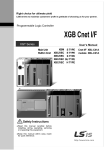
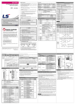
DATA SHEET LS Programmable Logic Controller Cnet(Computer Link) I/F Module Safety Precautions ► Safety Precautions is for using the product safely and correctly in order to prevent the accidents and danger, so please go by them. ► The precautions explained here only apply to this module. For safety precautions on the PLC system, refer to User’s manual. ► The precautions are divided into 2 sections, ‘Warning’ and ‘Caution’. Each of the meanings is represented as follows. If you violate instructions, it can cause death, fatal injury or a XGB Warning considerable loss of property XBL-C21A XBL-C41A Caution If you violate instructions, it can cause a slight injury or a slight loss of products ► The symbols which are indicated in the PLC and User’s Manual mean as follows. This symbol means paying attention because of danger of injury, fire, or malfunction ► This symbol means paying attention because of danger of electric shock. Store this datasheet in a safe place so that you can take it out and read it whenever necessary. Always forward it to the end user Handling Precautions ► Don’t drop or make impact. ► Don’t detach PCB from case. It may cause problem. ► When wiring, let no foreign material go into the module. If it goes into the module, remove it. ► Don’t detach the module from slot while power is on - When using LSIS equipment, thoroughly read this datasheet and associated manuals introduced in this datasheet. Also pay careful attention to safety and handle the module properly. - Store this datasheet in a safe place so that you can take it out and read it whenever necessary. Related Manual Read this data sheet carefully prior to any operation, mounting, installation or start-up of the product. Name Item Code XGB Hardware Manual 10310000693 XGB Hardware (IEC) Manual 10310001059 XBC Standard/Economic Manual 10310001091 XGK/XGB Instruction Manual 10310000510 XGI/XGR/XEC Instruction Manual 10310000833 XG5000 Manual 10310000821 XGB Cnet I/F User’s manual 10310000816 Revision V1.0 2008.02 V1.1 2009.08 V2.0 2011.05 V3.0 Applicable version For system configuration, the following version is necessary. Item Applicable version XBL-C21A, XBL-C41A V1.2 or above XBC H Type V2.02 or above XBC S Type V1.1 or above XBC SU Type V1.0 or above XEC H Type V1.1 or above XGB Module Type(XBM) V3.03 or above XG5000 V3.4 or above ► Protect the product from being gone into by foreign metallic matter. Risk of fire, electric shock and malfunction. ► Risk of fire, electric shock and malfunction. Risk of injury and fire by explosion and ignition. No 1 2 4 Caution ► Tighten the screw of terminal block with the specified torque range. If the terminal screw is loose, it can cause fire and electric shock. LSIS Beijing Office _ Beijing, China Tel: 86-10-5825-6027(666) Fax: 86-10-5825-6028 LSIS Guangzhou Office _ Guangzhou, China Tel: 86-20-8328-6754 Fax: 86-20-8326-6287 LSIS Chengdu Office _ Chengdu, China Tel: 86-20-8328-6754 Fax: 86-20-8326-6287 ► Be sure that external load does not exceed the rating of output module. Risk of fire and erroneous operation. e-mail: [email protected] e-mail: [email protected] Precautions for use PLC 8 9 10 ► Do not Install other places except PLC controlled place. ► Make sure that the FG terminal is grounded with class 3 grounding which is dedicated to the PLC. Otherwise, it can cause disorder or malfunction of PLC Others Others Standard 0 ~ 55℃ - -25 ~ 70℃ - Operating humidity Storage humidity 5 ~ 95%RH, non-condensing - 5 ~ 95%RH, non-condensing - For discontinuous vibration Acceleration Amplitude Frequency times 10≤f∠57 Hz 0.075 mm 10 times in Vibration 57 ≤f≤150 Hz 9.8㎨ (1G) each resistance For continuous vibration direction Acceleration Amplitude Frequency for 10≤f∠57 Hz 0.035 mm X, Y, Z 57≤f≤150 Hz 4.9㎨(0.5G) Max. impact acceleration : 147 ㎨ (15G) Shocks Authorized time : 11㎳ resistance Pulse wave : Sign half-wave pulse (Each 3 times in X,Y,Z directions) Square wave AC: ±1,500V impulse noise DC: ±900V Electrostatic Voltage: 4kV (Contact discharge) discharge Noise resistance Radiated electromagnetic field noise 80 ~ 1,000 MHz, 10 V/m Segment Voltage ► When disposing of PLC and battery, treat it as industrial waste. Risk of poisonous pollution or explosion. PLC Specification Fast transient /burst noise ► Do not disassemble, repair or modify the PLC. Risk of electrical shock, fire and erroneous operation e-mail: [email protected] LSIS Europe B.V., Netherlands Tel: +31 (0)20 654 1420 Fax: +31(0)20 654 1429 e-mail: [email protected] 7 Item Operating temperature Storage temperature ► Do not use the PLC in the environment of direct vibration Risk of electrical shock, fire and erroneous operation. e-mail: [email protected] LSIS Qingdao Office _ Qingdao, China Tel: 86-532-8501-6068 Fax: 86-532-8501-6057 e-mail: [email protected] 6 ► Use the PLC in an environment that meets the general specifications contained in this datasheet. Risk of electrical shock, fire, erroneous operation and deterioration of the PLC. e-mail: [email protected] LSIS Shanghai Office _ Shanghai, China Tel: 86-21-5237-9977(609) Fax: 89-21-5237-7189 5 ► Be sure to check the rated voltage and terminal arrangement for the module before wiring work. Risk of electric shock, fire and malfunction. . LSIS Tokyo Office _ Tokyo, Japan Tel: 81-3-3582-9128 Fax: 81-3-3582-2667 Description first edition address updated Performance Spec. updated Branch address changed KOREAN/ENGLISH data sheet integrated CI Changed 1. General Specifications ► Do not contact the terminals while the power is applied. Risk of electric shock and malfunction. e-mail: [email protected] Operating Mode P2P Server XBL-C21A XBL-C41A RS-232C 1 Channel RS-422/485 1Channel Dedicated protocol for LS Industrial Systems Modbus ASCII/RTU protocol User-defined Protocol Dedicated protocol for LS Industrial Systems Modbus ASCII/RTU protocol 7 or 8 1 or 2 Even / Odd / None Asynchronous type Data Bit Stop Bit Parity Synchronization Type Communication speed 1200/2400/4800/9600/19200/38400/57600/115200 (bps) Set by using XG-PD, Max. 32 stations are able to be set Station No. Setting (from 0 to 255) Max. 15m Transmis- RS-232C (Extendible with MODEM) sion RS-422 Distance Max. 500m /485 Terminator 120(1/2W) Indication of operating status with 5 LEDs during Diagnosis Function operating. Current Consumption 100 (mA) Weight(g) 60 55 5Pin Terminal Block Accessory Data Type Revision History Date 2006.11 3 LSIS(ME) FZE _ Dubai, U.A.E. Tel: 971-4-886-5360 Fax: 971-4-886-5361 Specifications Item Serial Communication Channel 3. Cable Specifications Warning HEAD OFFICE LS Tower, 127, LS-ro, Dongan-gu, Anyang-si,Gyeonggi-do, 431-848, Korea Tel: 82-2-2034-4870 Fax: (82-2)2034-4648 e-mail: [email protected] 2. Performance Specifications PLC 11 Ambient conditions Operating height Pollution degree Cooling type Power supply module Digital/analog input/output communication 2 kV interface 1 kV - IEC61131-2 IEC61131-2 LSIS standard IEC61131-2 IEC61000-4-2 IEC61131-2 IEC61000-4-3 IEC61131-2 IEC61000-4-4 No corrosive gas or dust - 2000m or less - 2 or less - Natural air cooling - (1) When using RS-422 or RS-485 communication channel, a twisted pair cable must be used with consideration of high-quality signal transmission and control characteristic. (2) Table 4.1 describes recommended specifications of cable. Also when using another cable than recommended one, the cable conformed to characteristics of Table 4.1 shall be used. Item: Low Capacitance LAN Interface Cable Type: LIREV-AMESB Size: 2P X 22AWG(D/0.254 TA) Manufacturer: LS Cable Co., Ltd. (3) Electrical characteristics Item Specified Value Dielectric strength test No break down Insulation resistant test Min. 1,000 ㏁.㎞ Capacitance Max. 45 ㎊/M Characteristic 120 5 Impedance Test Condition 500V/1min 20 ℃ 1 ㎑ 10 ㎒ [Table 4.1] Specification of Cnet I/F module twisted pair cable (4) Appearance characteristics Item No. of pair Size Conductor Composition Diameter Thickness Insulator Diameter Unit Pair AWG No./㎜ ㎜ ㎜ ㎜ Specified Value 2 22 7/0.254 0.76 0.59 1.94 Others Homepage: http://eng.lsis.biz A) Best LS constantly endeavors to improve our products so that information in this datasheet is subject to change without notice. The date of issue: 2011. 5 10310000734 Ver 3.0 4. Parts Name and Descriptions ► ► ► ► ► B) Good C) Bad Connect expansion connector correctly when expansion module is needed. Do not detach PCB from the case of the module and do not modify the module. Turn off power when attaching or detaching module. Cellular phone or walkie-talkie should be farther than 30cm from the PLC. Input signal and communication line should be farther than 10cm from a hightension and a power line in order not to be affected by noise and magnetic field. (d) How to connect terminal resistor [RS-422 connection] (a) How to connect RS-232C connector to the external modem 7. Dimension (㎜) Cnet I/F module can communicate with devices of long distance through a modem at this time modem and channel RS-232C must be connected as shown in below table Cnet(9-PIN) Pin No. Name 1 CD 2 RXD 3 TXD 4 DTR 5 SG 6 DSR 7 RTS 8 CTS 9 RI Connection No. and Signal Direction Modem Name CD RXD TXD DTR SG DSR RTS CTS RI (e) How to connect terminal resistor [RS-485 connection] (b) How to connect RS-232C connector in null modem mode. In null modem mode, connector is able to be connected in 3-line (without handshake) type. Cnet(9-PIN) No. ① ② ③ No. ④ LED Name RUN Name LED Indicators RS-232C Connector RS-422/RS-485 Connector Switch status All on All off LED Descriptions Cnet operation status I/F Interface Status with Main Unit TX During frame transmission RX During frame receiving ERR Frame error Descriptions Shows the operation status The connector for external connection The connector for external connection Switch status descriptions Normal operating OS Download Mode (If you want to OS Download, Please contact us) Pin No. 1 2 3 4 5 6 7 8 9 Name CD RXD TXD DTR SG DSR RTS CTS RI LED status descriptions Pin No. Name On Normal operating Abnormal operating of Cnet I/F Module Normal operating Interface error with Main Unit During frame transmission Frame transmission completed During frame receiving Frame receiving completed Frame Error Normal frame 1 2 3 4 5 TX+ TXRX+ RXSG Off Off On Off On Off 5. Installation and Wiring (1) RS-232C Interface (XBL-C21A) RS-232C channel uses 9-pin female connector for communication with external devices Signal direction Pin Name Function (Cnet<-->External Description No. device) Note1) DCE inform carrier 1 CD Carrier Detect detection to DTE 2 RxD Received Data Received data signal 3 TxD Transmitted Data Transmitted data signal Note2) DTE inform Data Terminal 4 DTR communication ready Ready to DCE 5 SG Signal Ground Signal ground line DCE inform 6 DSR Data Set Ready communication ready to DTE DTE require data 7 RTS Request To Send transmission to DCE DCE inform ready to 8 CTS Clear To Send transmit to DTE Note3) DCE inform receiving 9 RI Ring ‘Ringing Tone’ to DTE [Pin assignment of RS-232C 9-pin connector] This module can communicate with other device directly or through Modem for a long distance. The kind of the Modem is selected by using XG-PD. Remarks Note1) DCE: Data Communication Equipment Note2) DTE: Data Terminal Equipment Note3) RI: This Pin is not used in XBL-C21A (This pin is not connected to the internal electric circuit of XBL-C21A) Computer /Communication device Name CD RXD TXD DTR SG DSR RTS CTS RI (2) RS-422/485 Interface (XBL-C41A) RS-422 channel uses 5-pin terminal block for communication with external devices. The names and functions of pins, and data directions are as shown in the following table. LED status Blink Off On Connection No. and Signal Direction Signal direction (Cnet<-->External device) Function Transmitted data (+) Transmitted data (-) Received data (+) Received data (-) Signal ground line [Pin assignment of RS-422 5-pin connector] RS-422 channel makes connection external devices and RS-422 and RS-485(Multi-drop) possible. When RS-422 channel is used as multi-drop, set channel RS-422 to RS-485 communication in setting menu of RS-422 communication type of XG-PD, and connect the terminal of RS-422 as shown in the [RS-485 connection] table. Cnet Pin No. 1 2 3 4 5 Name TX+ TXRX+ RXSG Signal direction (Cnet<--->External device) External device RX+ RXTX+ TXSG [RS-422 connection] Cnet Pin No. 1 2 3 4 5 Name TX+ TXRX+ RXSG Signal direction (Cnet<--->External device) External device RX+ RXTX+ TXSG [RS-485 connection] Above figure shows how to connect RS-485 multi-drop communication. In the case of RS-485 communication, the TX+ and RX+ terminals should be shortened and TX- and RX- terminals should be shortened, then connected to the other devices. At this time,RS-485 should be selected by using the XG-PD. (3) Terminator (RS-422/485) (a) When the communication via channel RS-422 terminal resistor from external must be connected. (b) Terminal resistor has the function to prevent distortion of signal by reflected wave of cable when long distance communication, the same resistor (1/2W) as characteristic impedance of cable must be connected to terminal of network. (c) When using the recommended cable in the section 3, connect terminal resistor of using another cable than recommended one, the same resistor (1/2W) as characteristic impedance of cable must be connected to both ends of cable. 6. Cautions for system and network connection (1) All the stations in whole network should not have duplicated station number. Otherwise, it can cause serious communication error. (2) Use cable complying with specification in this data sheet. Otherwise, it can cause a serious communication error. (3) Make sure that communication cable does not break or short. (4) Make sure that cable connector is fastened. Loose connection could cause serious communication error. (5) Improper cable connection (snarled cable, redundant connection) can cause communication error. (6) The communication type and parameter can be set with XG-PD. (7) After the installation of the Cnet I/F module, refer to the section 5. Installation and Wiring for system configuration. (8) While the power of the Main Unit is on, mounting/dismounting of module will cause system error and the CPU module halted. Therefore, turn the power off during replacing or repairing module. 8. Warranty (1) Warranty period LSIS provides an 18-month-warranty from the date of the production. (2) Warranty conditions For troubles within the warranty period, LSIS will replace the entire PLC or repair the troubled parts free of charge except the following cases. (a) The troubles caused by improper condition, environment or treatment except the instructions of LSIS. (b) The troubles caused by external devices. (c) The troubles caused by remodeling or repairing based on the user’s own discretion. (d) The troubles caused by improper usage of the product. (e) The troubles caused by the reason which exceeded the expectation from science and technology level when LSIS manufactured the product. (f) The troubles caused by natural disaster. (3) This warranty is limited to the PLC itself only. It is not valid for the whole system which the PLC is attached to.